-
Schumacher Cougar SV -
Words & Pictures: Arn0
Transmission
Only for the second time, Schumacher
does not use a belt transmission on his two wheel drive buggy, the
previous one being the Cougar 2000. So the SV owns a brand new
transmission with four gears plus the usual spur-pinion, without
taking in consideration the differential spur. At the end of the day,
that makes five gears, impressive for a two wheel drive.
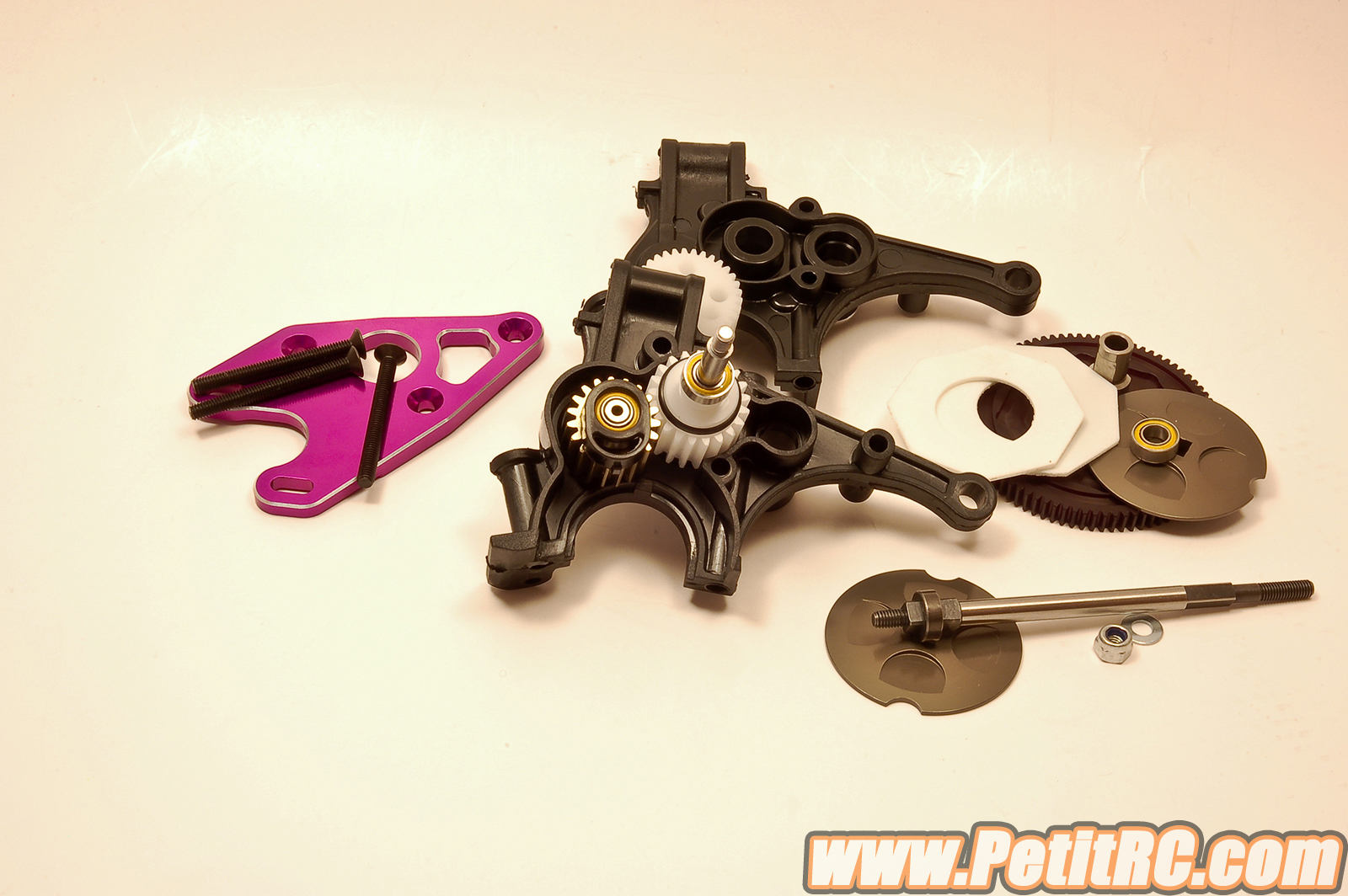
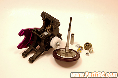
To get it done, seven bags need to be
opened!! Here are the components of this transmission:
- 3 pins
- 6 bearing
- 2 seals
- 2 eccentrics
- 4 gears
- 2 housings
- 1 motor plate
- 3 screws
- 3 shafts
- 3 spacers
- 4 washers
- 2 nuts
- 1 spring
- 2 slipper plate
- 2 slipper pad
- 1 machined spur
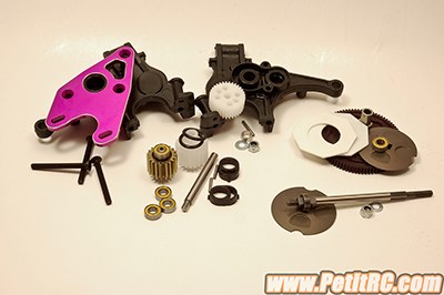 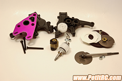
That makes a total of forty
one items. There are this many components because this transmission is
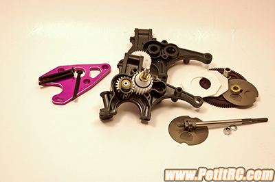
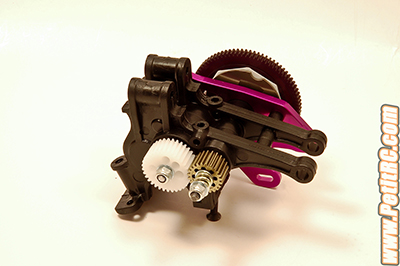
adjustable in different ways. Let’s have a quick overview of the four
major assemblies detailed below:
1
- the transfer shaft with the slipper clutch already seen on the Cat
SX
2
- the layshaft with it’s gear
3
- the height-adjustable idle gear
4
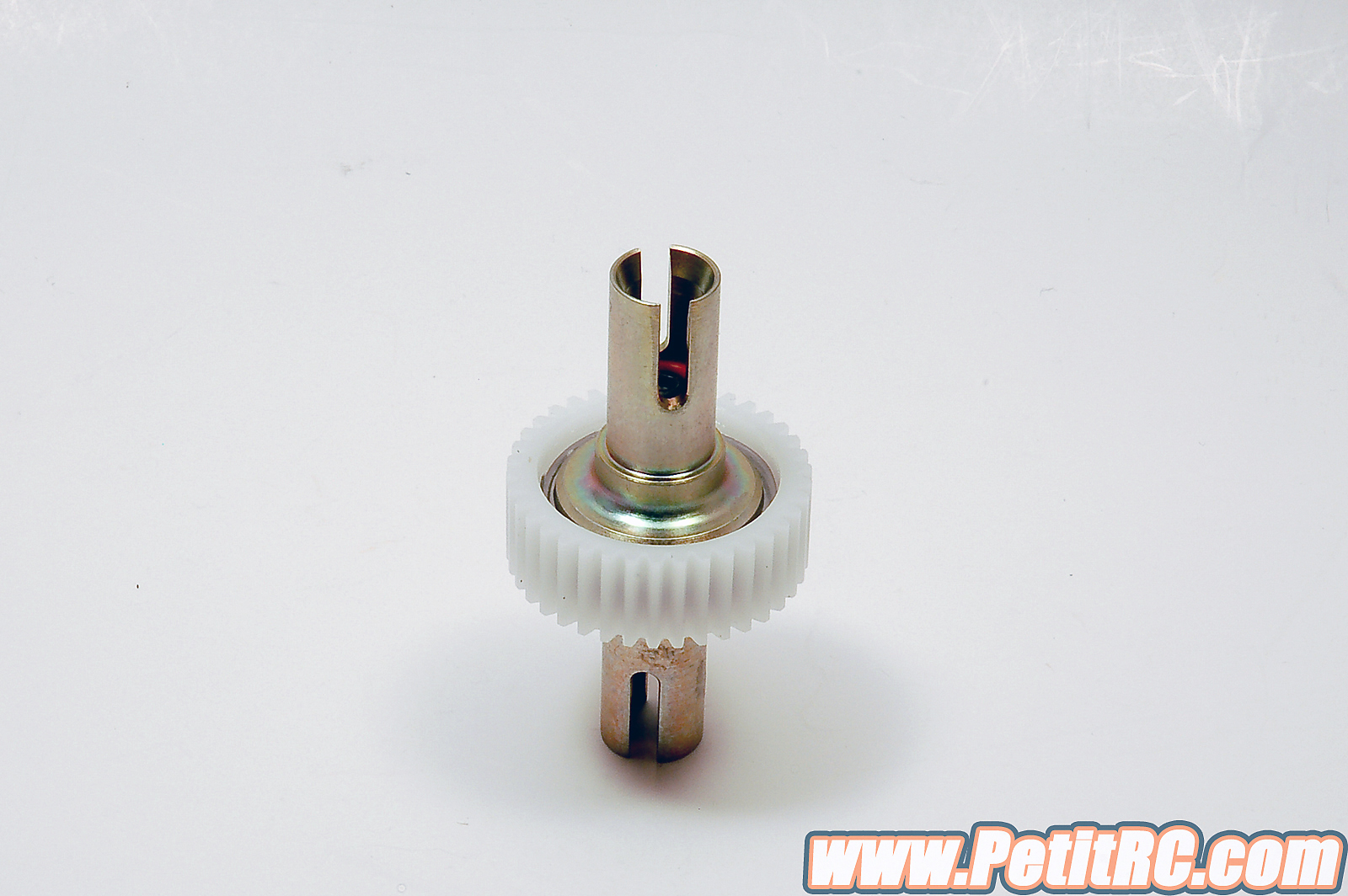
- the differential
By default, the internal
ratio is 2.6:1, kind of a magic number in 2wd, and it is defined as
'medium internal ratio'. 'Medium internal ratio', that means there is a
'high internal ratio' and a 'low internal ratio'. This can be achieved
but replacing a set of pinions: the ones on the outside of the gearbox.
Per kit, you have a 23 tooth and a 33 tooth, but you may switch for
22/34 to get the 'high internal ratio' for hi rev motors. 'Low internal
ratio' is established by combining a 24 tooth gear with a 32 tooth
one which is a better fit for low rev motors such as those dedicated to
the stock class. In every case, fine tuning of the final drive ratio is
still achieved with the inseparable spur-pinion.
It is possible to set the
transmission height, a setting that appeared some years back but is very
useful to increase or reduce traction of the rear end. In the present
case, the casing will always stay in the same position, meaning some
eccentrics located around the differential will allow the adjustment of
this parameter. But to do so, one gear - and consequently a shaft -
needs to move up or down, which is done by the eccentrics inside the
gearbox.
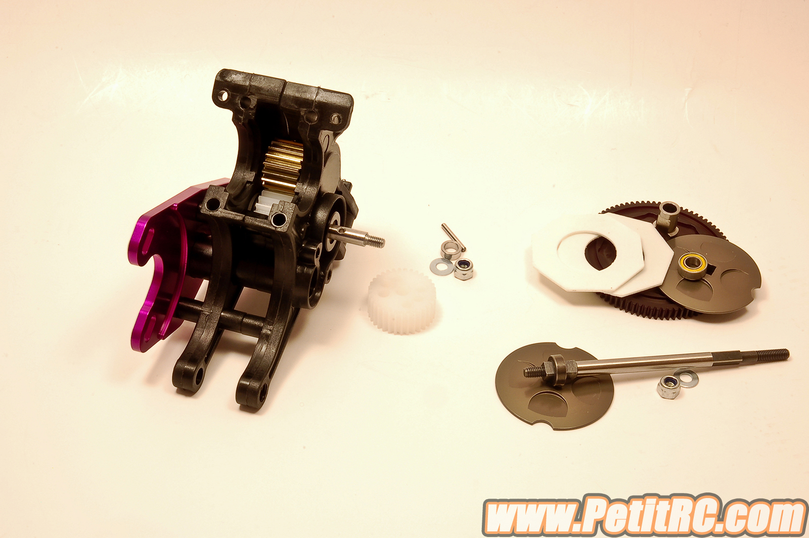
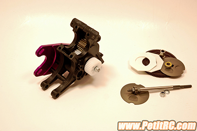
Before pushing forward, let’s
have a better view of the layshaft gear inside the gearbox. This gear is
mounted on a shaft with two pins; these two pins are held on by two
o-rings. Fresh mounted, that looks good. But projecting ourselves into
the future, the o-ring may dry, the pins may push on those o-rings and
at one moment, one of the pins might escape and have a nice and
devastating journey inside the casing. You get the point: bye-bye
internal gears. So, while mounting this gear, you can either replace the
pins by roll pins or use a tiny drop of glue to avoid any pin movement.
Of course, some other alternative solutions may appear.
Done with the rotational
parts, let’s have a look at the fixed parts. The motor mount is a
one-sided chamfered purple anodized 4mm aluminum plate, a nice look
piece to cool down the motor. The two others fixed parts are the
housings. Complex molded items with a lot of recesses and details, the
twins may have cost Schumacher some effort. The internal shape is well
made, no play between gears, shaft distances are good with the provided
external gears and no doubt will work great with the optional ones
described above. But strangely enough, there is no lip all around one of
the housings to provide sealing. Look deeply at the shape, it is
impossible to get this lip done as the casings are almost symmetrical
and molding processes do not allow the fabrication of this lip. To get
it in place, the housing should have been asymmetrical or with an
additional piece, but would probably be even more complex to produce.
Here, only the design team gets the answer and the final decision was a
compromise between various parameters, as always in engineering.
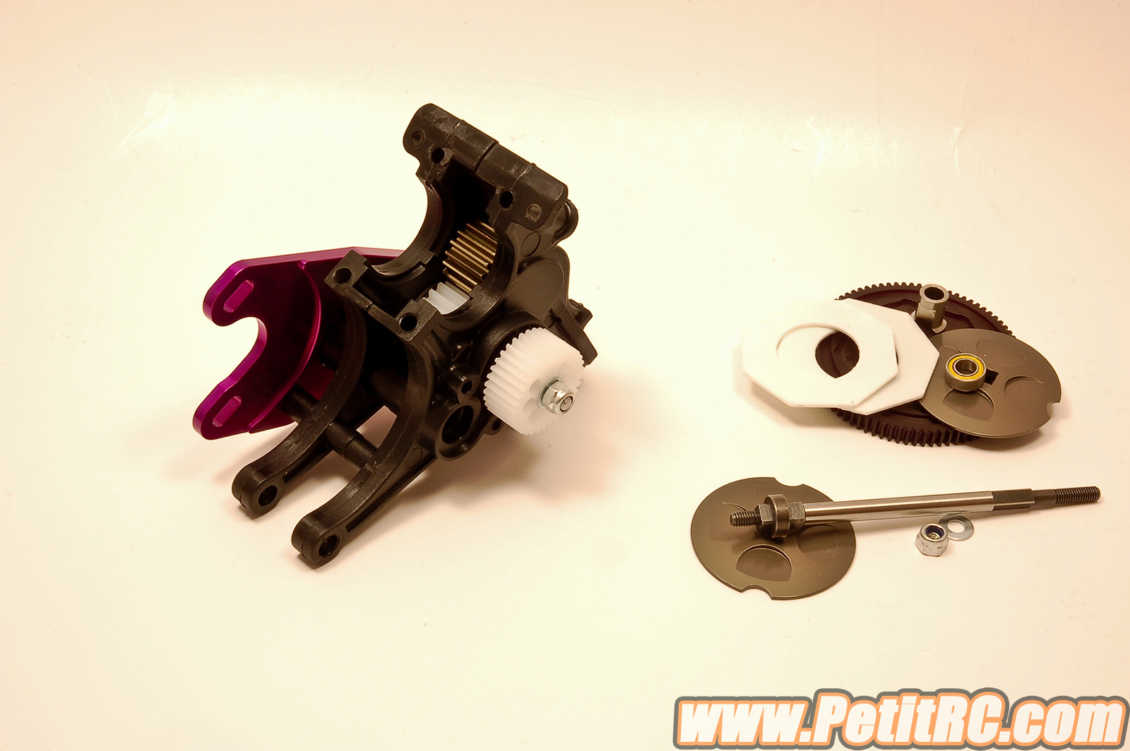
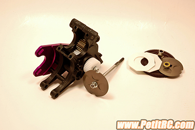
The assembly is in fact
pretty straight forward. Be sure to install one eccentric on each
housing and in the same position. As recommended, the differential will
be set low to get the highest traction possible so the idle gear must be
positioned low, otherwise you won't have mesh contact and consequent
motion while accelerating.
As standard equipment, the
transmission is loaded with a slipper, the basic system designed years
back. The components are the same as the ones from the Cat SX, so no
surprise. And as the 4wd, the setting will be realized from the other
side of the spur location.
Once together, the whole
transmission runs smoo... almost smooth, there is one spot where you can
feel some resistance, a hard spot most probably due to a tiny something
on the nylon gear located before the metal one. That will disappear
after a little break-in.
One advice that will be
useful while putting the transmission into place, do not tighten the
three screws holding the motor plate and so, do not install the spur and
the related items.
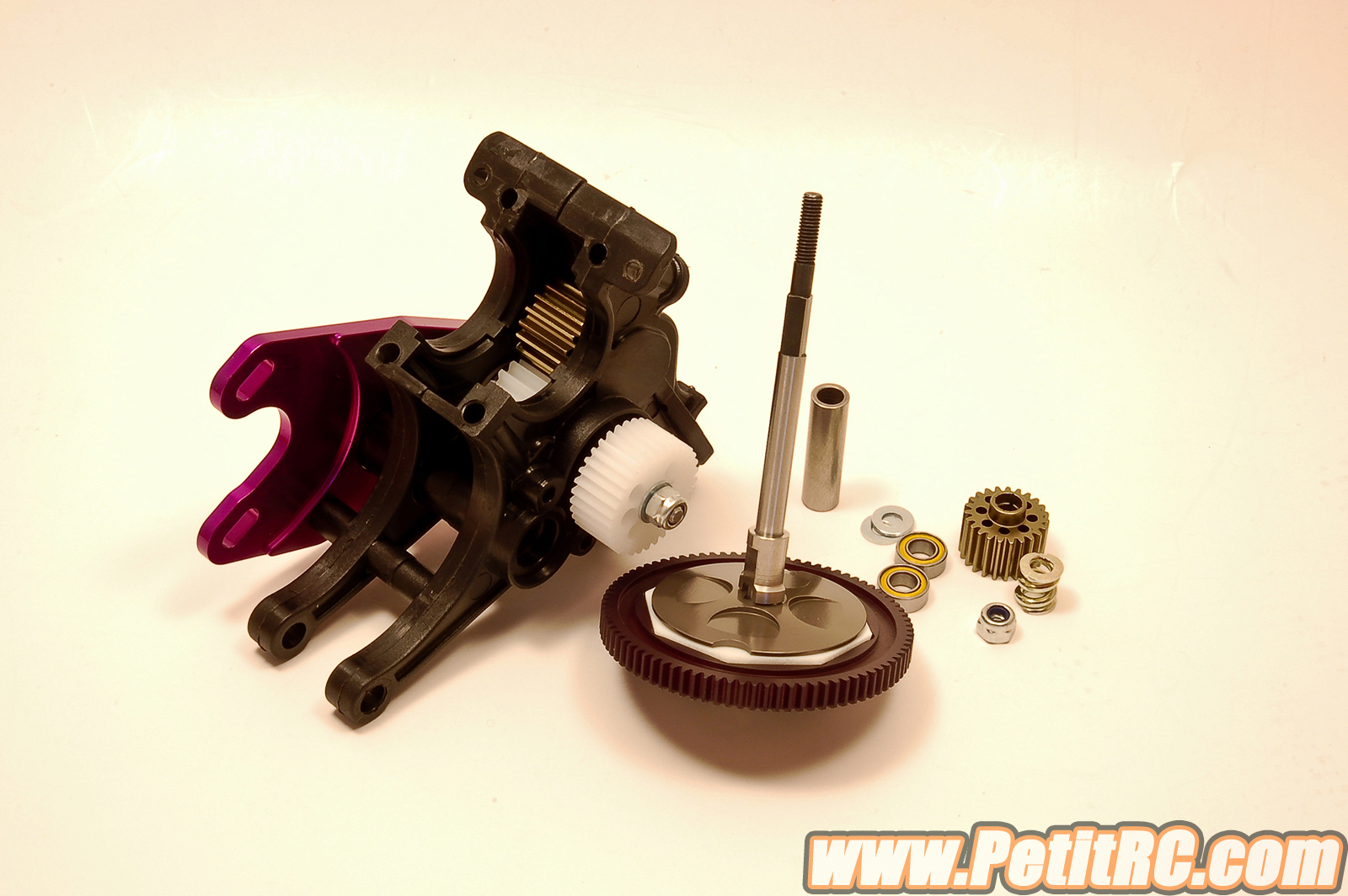
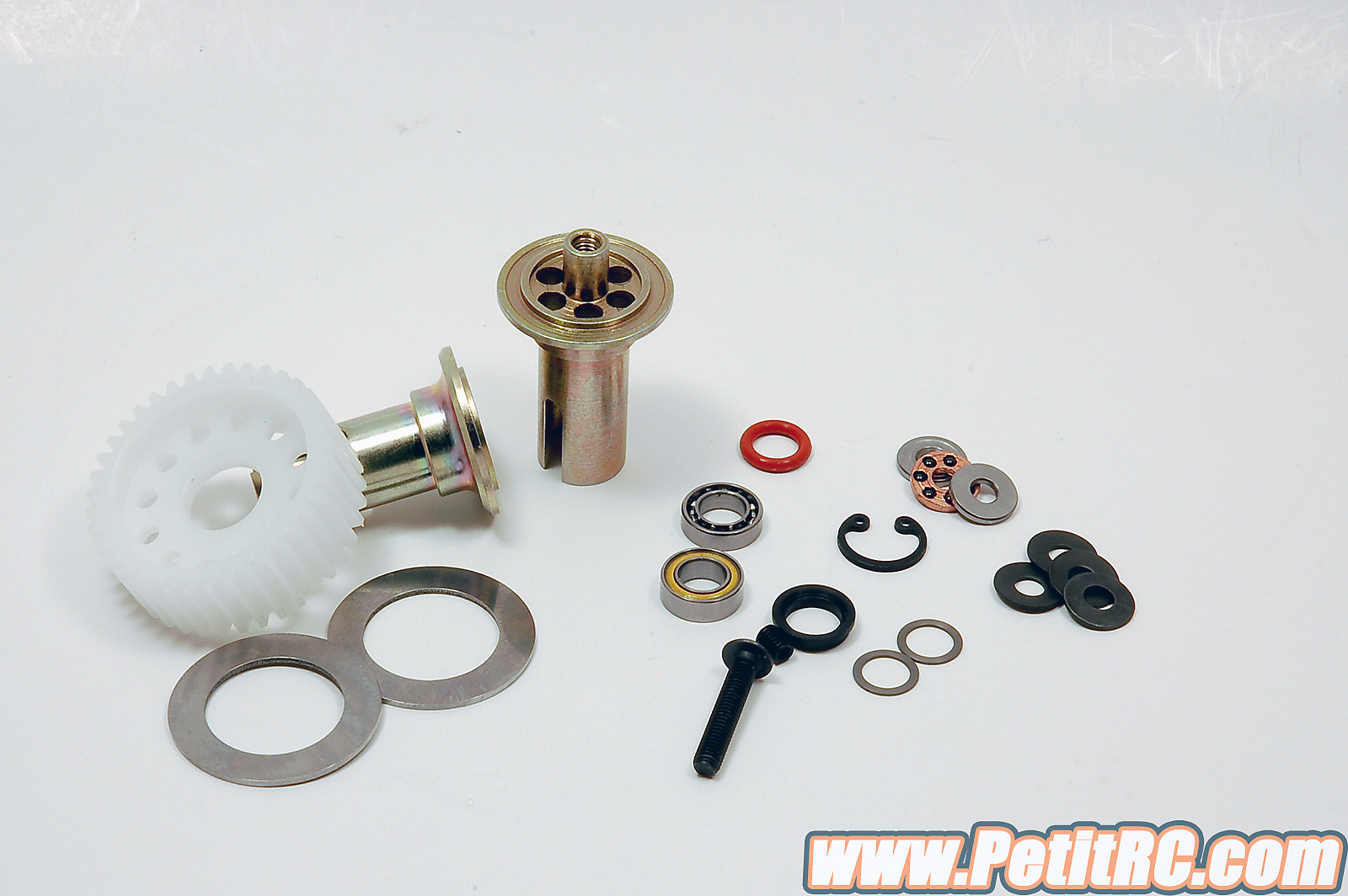
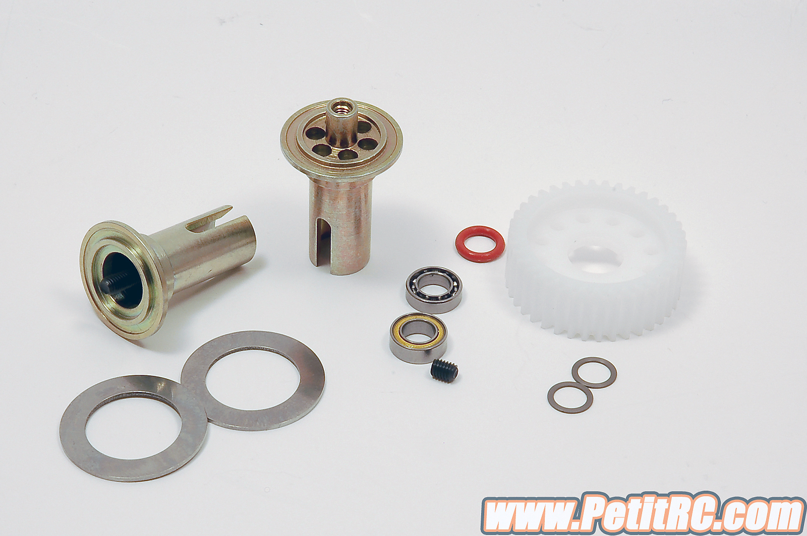
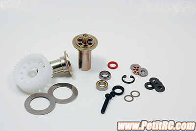
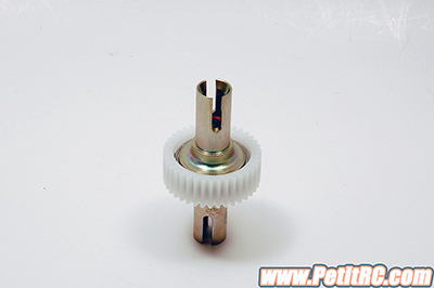
Differential
To get the transmission
fully done, the differential is the next step.
First point to note, an
additional sheet giving some advice on a specific point of this part of
the car's assembly; the mounting of a circlip with dedicated pliers,
provides advice for this procedure.
The design is the same as
the one for the Cat SX, just to note a thrust bearing and four
Belleville type disc springs are fitted on a fully threaded screw. The
use of a fully threaded screw is weird as one of the thrust bearing
washers will come in contact with the thread at one point. In the first
instance, it’s worth the try as is works fine on the 4wd but switching
for a partly threaded screw would be a good idea. This assembly sits
inside one output once installed from the inside of the differential and
not from the outside.
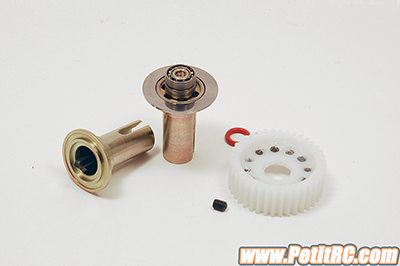
Others designs are based on
the use of a spring and nut, both located on the opposite output where
the thrust bearing is located. The Schumacher design makes the screw
tightening directly on the opposite output, meaning no nut, and a
headless screw secures the whole package.
The assembly is pretty
straight forward. The thrust bearing discs are not the same thickness,
the difference is minimal so be careful. Also be patient while putting
on the circlip, it can be twisted slightly to avoid any freedom and take
care how you insert it as the additional sheet is very clear about that.
You may add a spot of glue to make sure this circlip won’t move. The
differential will be adjusted once the car is done, tightened enough to
be borderline loose.
|