|
- Part 2 – Front Suspension -
Previous - Main - Next
The Build – Part 2 - Front Suspension
The front suspension is pretty straight forward and includes quite a bit of tuning. AE has opted to use inserts to adjust alot of the front end, including caster and axle location.
Build Notes:
> We used, once again, the silver Sharpie to highlight the parts steering block and caster block inserts in this step.
Step 12
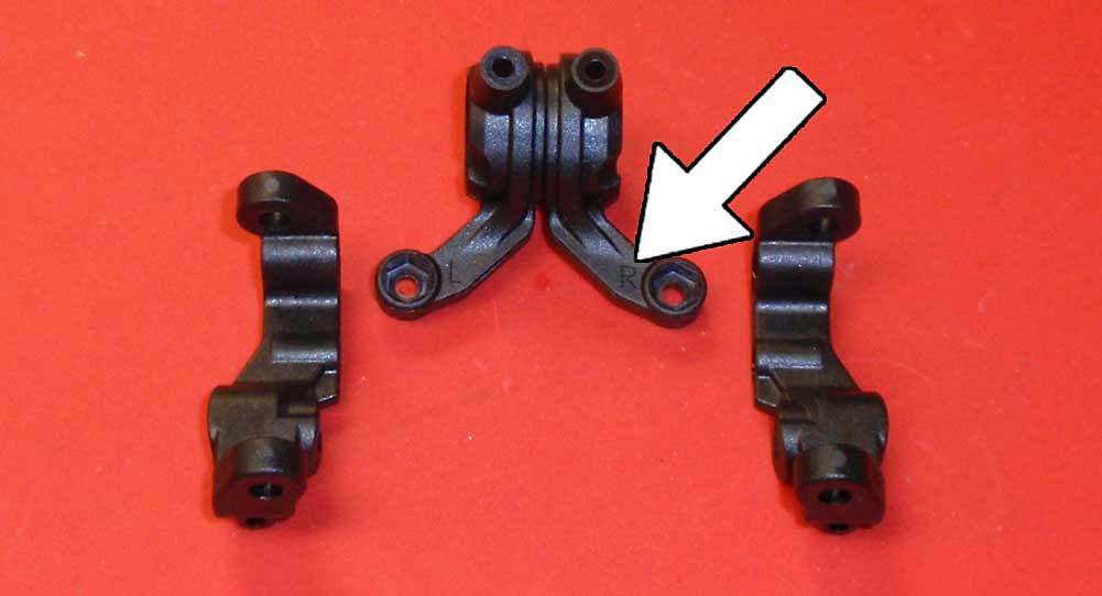
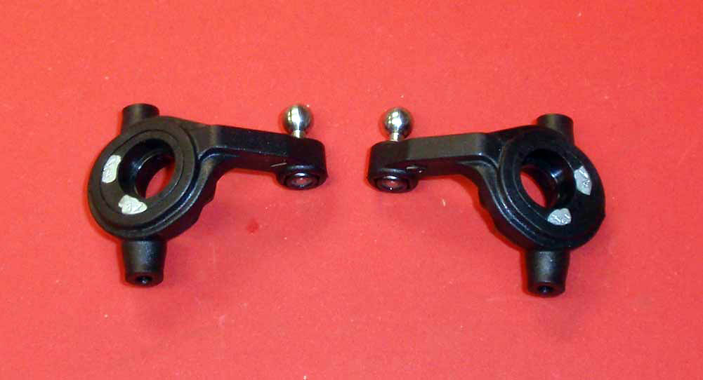
Before we start assembly, get familiar with the left and right parts being used. The caster blocks are obviously different, however the steering blocks have a small L and R molded into them (see the arrow). I would suggest keeping the left and right parts together but separate on your bench so you don’t mix them up.
Step 13
Install the heavy duty ballends into the steering blocks, using the M3 locknut to keep them in place.
Step 14
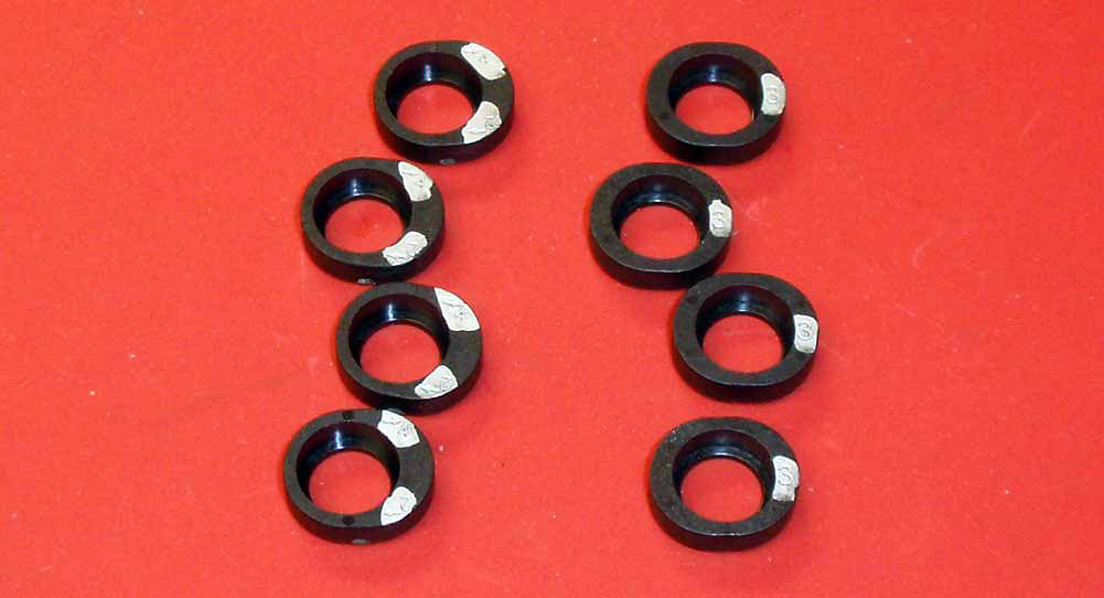
A look at all of the steering block inserts, Sharpied up for easy reference. We’ll be using the 2/4° trailing insert for this build (set to 4°).
Step 15
Press the inserts into the steering blocks, making sure the highlighted area, or 4° arrow, is facing away from the ballstud as shown.
Step 16
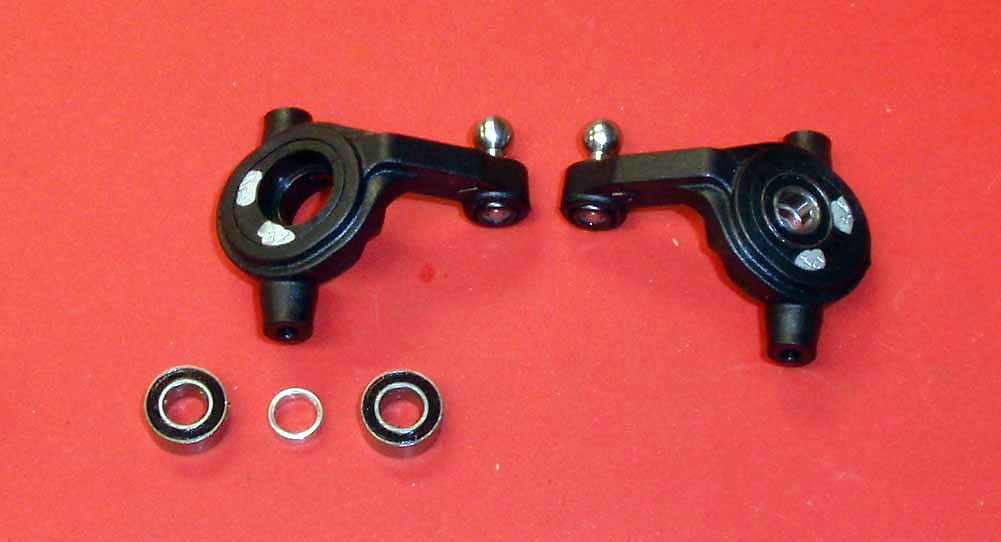
Install the bearings with the aluminum crush washer in between.
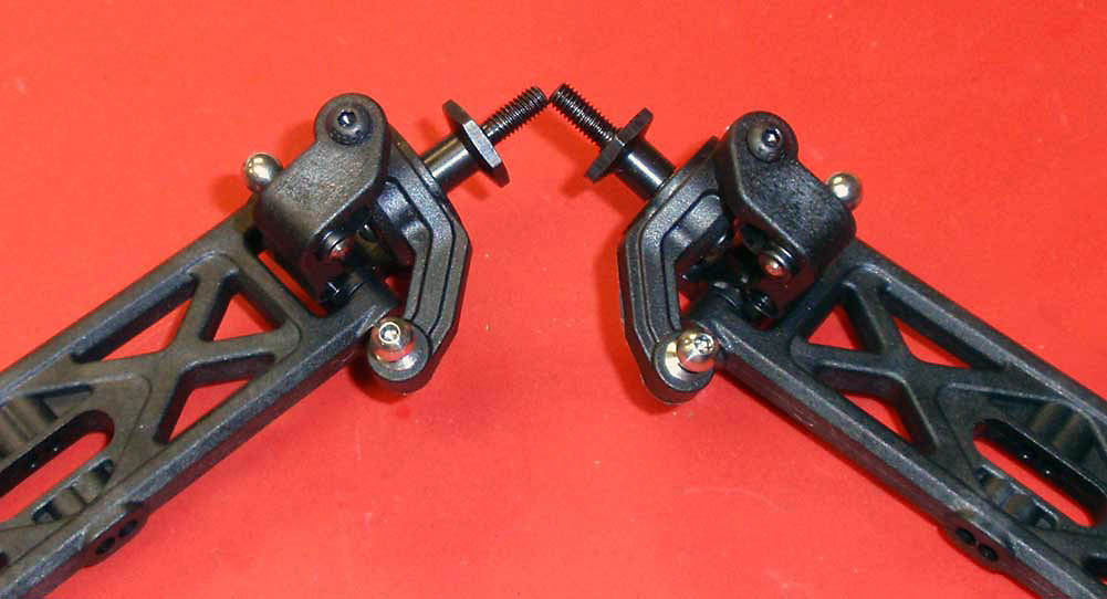
Step 17
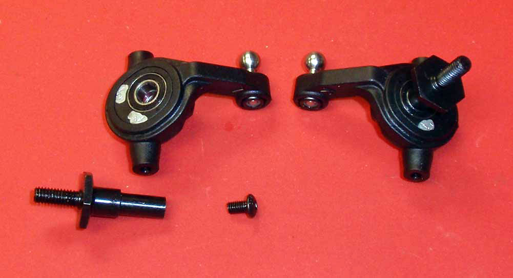
Insert the T5 axles through your bearing assembly and secure with the 5mm screw. A light dab of threadlocker is suggested here to keep the screw from backing out.
Step 18
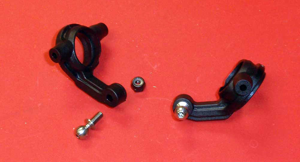
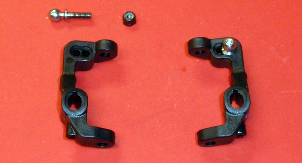
Install the heavy duty ballstuds into the caster blocks, using the M3 locknut to secure. Note the orientation of the blocks.
Step 19
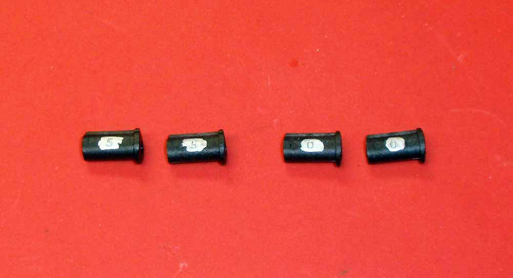
The T5M comes with 2 inserts; a 0° and a 5°. We’ll be using the 5° per the manual, highlighted for easy reference.
Step 20
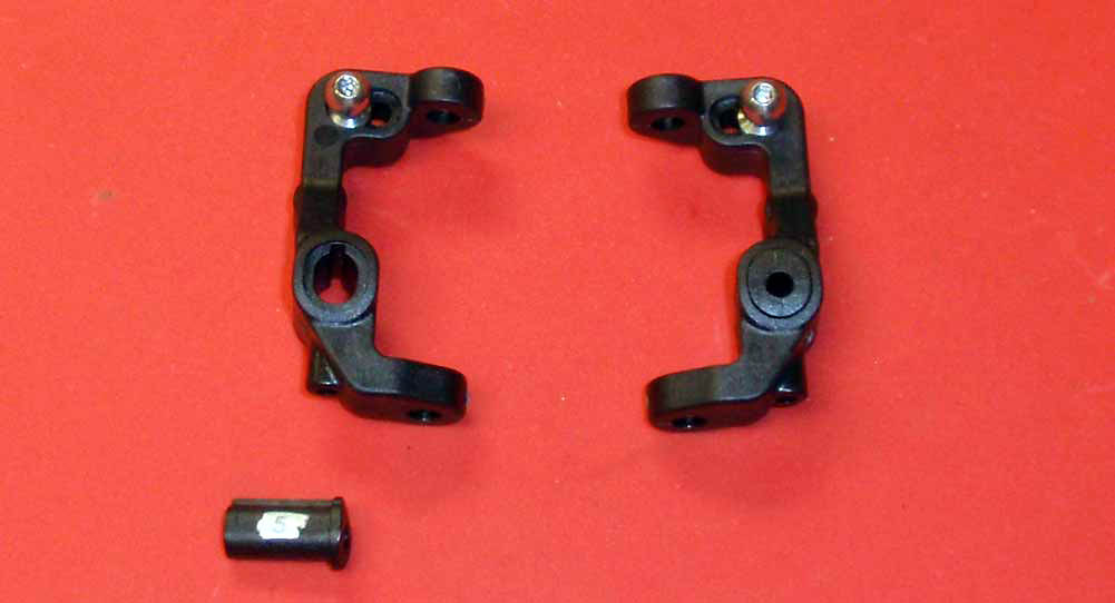
Install the caster inserts. Note the orientation of the caster blocks.
Step 21
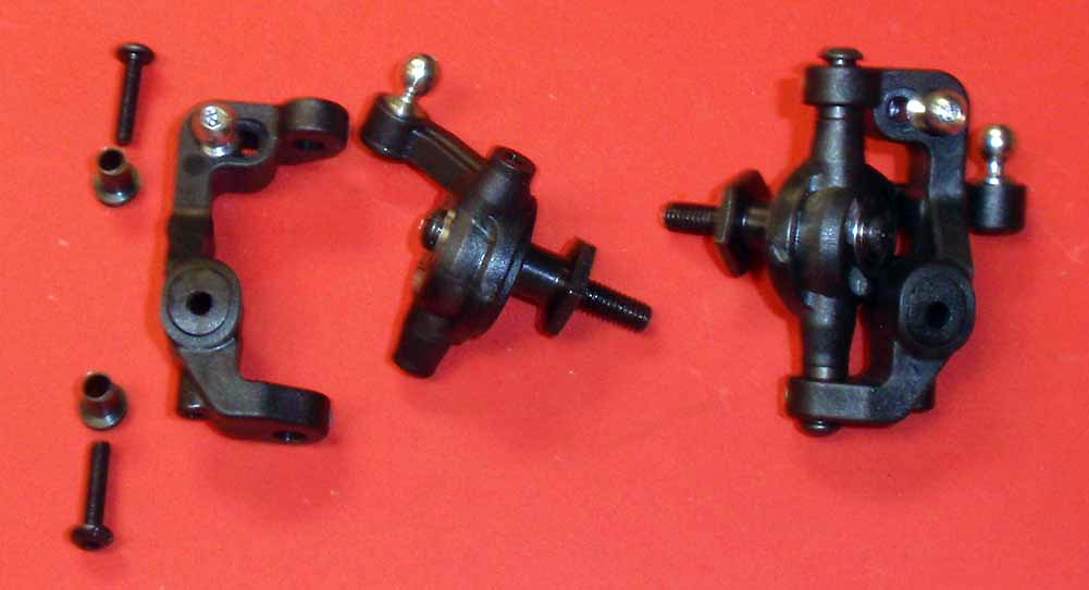
Time to mate the steering blocks with the caster blocks. First, make sure you have the left steering block attaching to the left caster block. Slip the caster block bushings into the caster block, then slide the steering block into place and secure with the pair of 12mm screws. SLOWLY tighten all the way down, then backing off about 1/8 of a turn. Test the steering block; if it feels tight, back the screws off another 1/8 of a turn and re-test. You want the screws tight without hindering the swivel movement of the steering block.
Step 22
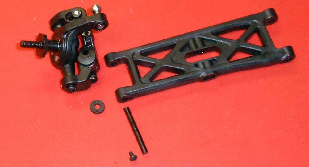
The T5M uses the same front arms on both the left and right of the truck. Note the orientation of the suspension arm, then insert the hinge pin through the arm, then the plastic spacer and then the steering assembly. Secure the pin with the 4mm screw.
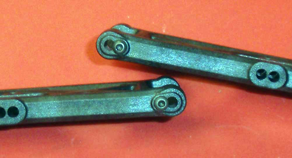
Step 23
After assembly, your suspension arms should look like this.
Step 24
Now to attach the arms to the chassis. Start by installing the 4mm hinge pin retaining screw as shown.
Step 25
Slip the suspension arms around the front bulkhead and slide the long hinge pins into place.
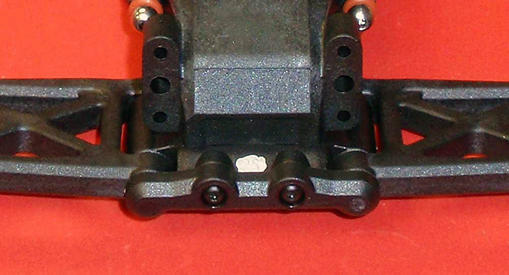
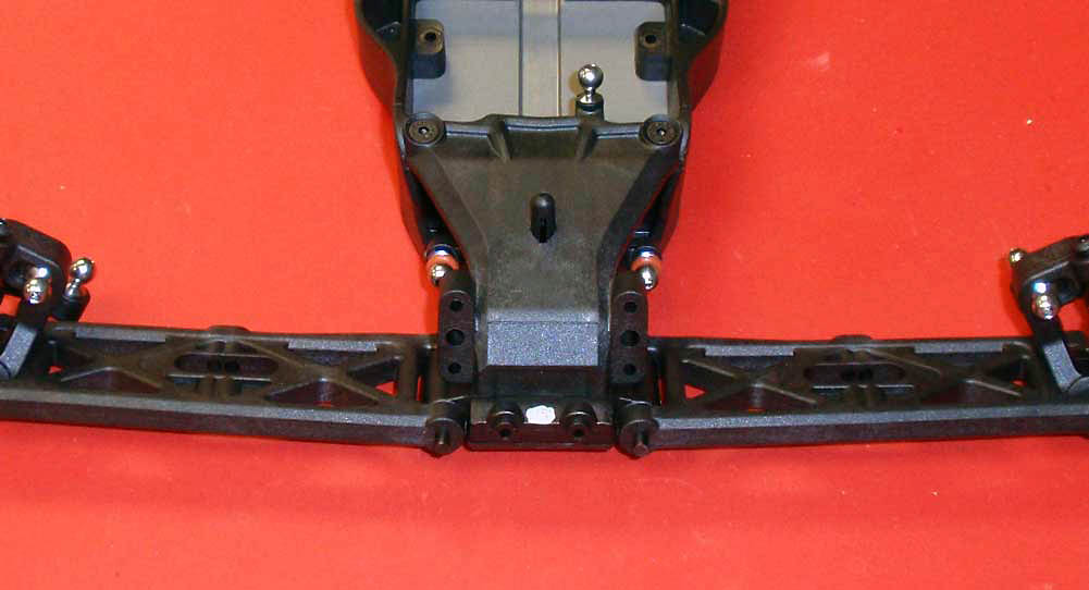
Step 26
Attach the hinge pin brace. Give the front arms a quick swivel to make sure they move freely. If not, turn the truck up on its end and tap lightly on the suspension arm. Sometimes things are a little tight and need a little massaging.
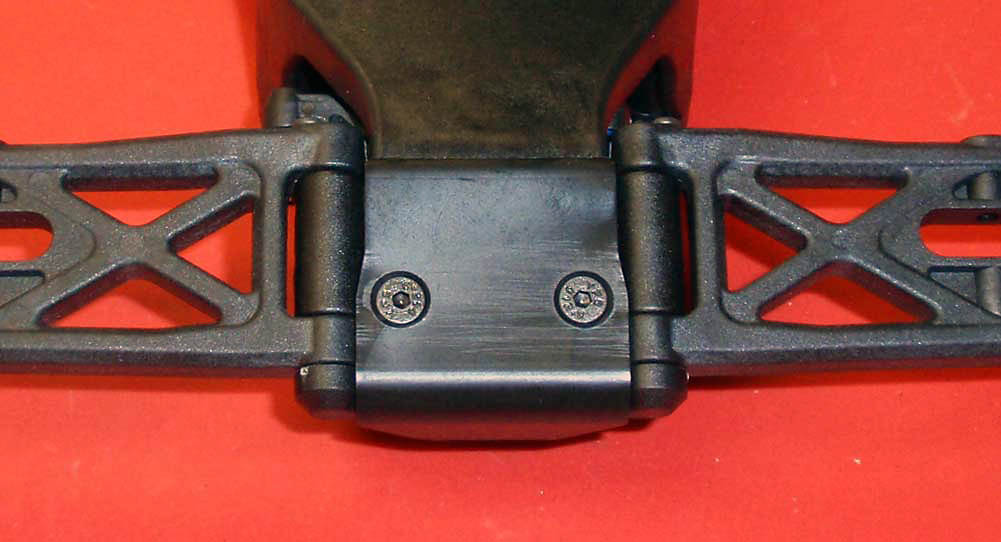
Step 27
Flip the T5M over and attach the front bumper.
 Step 28 Step 28
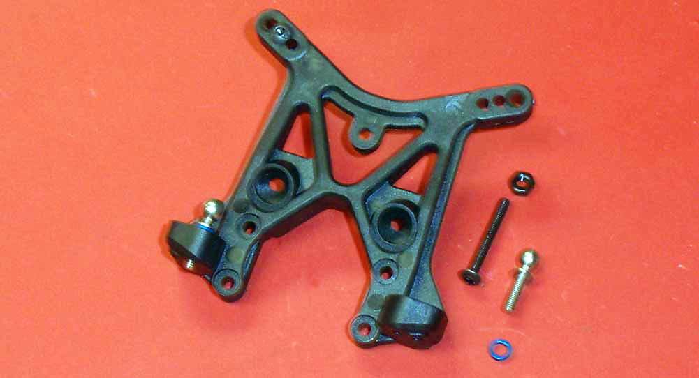
Assemble the front shock tower using the middle hole for the upper shock mount and the inside hole for the camber link mount.
Step 29
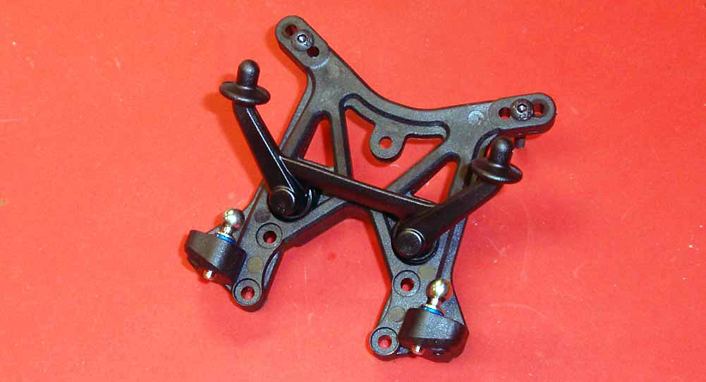
Attach the front body mount to the tower.
Step 30
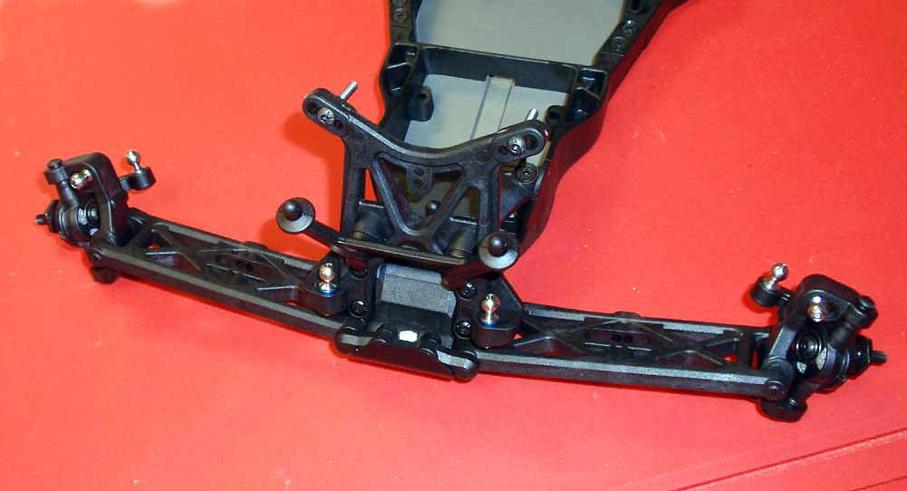
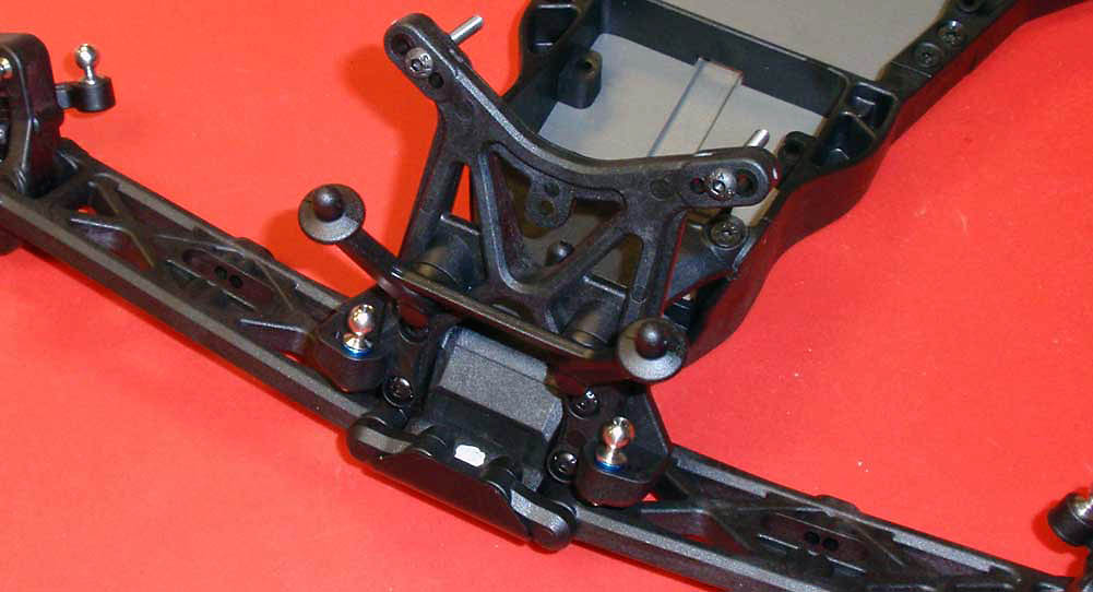
Attach the assembled shock tower to the front bulkhead.
The front suspension is done and looking good.
Previous - Main - Next
|
