|
- Team Associated RC10 Classic - Build -
Page 1 - Page 3
First steps
We are ready to start building the RC10 Classic from Associated! In the last post (above), we showed you an extensive unboxing (including video!) that gave you a close-up view of everything you get in the kit. This time, we’ll complete the first steps of the kit assembly, starting with bags A and AA!

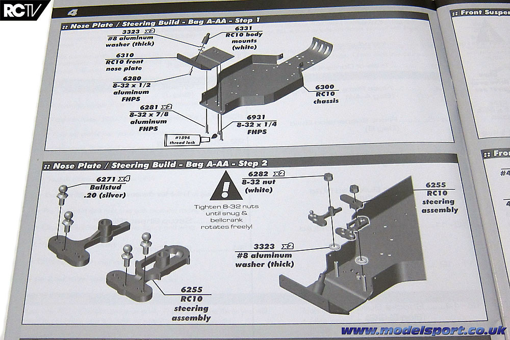
The first two steps of the assembly process have you open bags A and AA. You can clearly see what’s to be done. It’ll be interesting comparing this build to modern kit builds and assembly manual expectations. So far it’s looking good, but a little strange to see modern CAD drawings used for old-style parts!
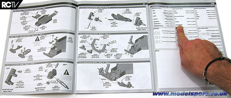
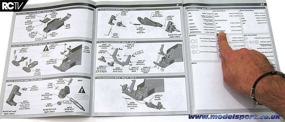
The back page of the manual conveniently folds out so you can get the true size of the hardware you need to assemble each step. Very handy! Here, I’m holding one of the gold screws to its representation in the manual – a very handy way to make sure you’re installing the correct parts…and I did have to refer to this a couple of times, since I accidentally used the wrong screws in one area!
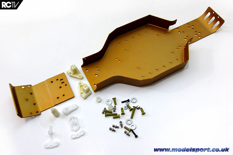
Here’s all the parts that are in bags A and AA. Strangely, you don’t actually use all of the parts and hardware in this step, but the leftovers are used in the next series of steps.
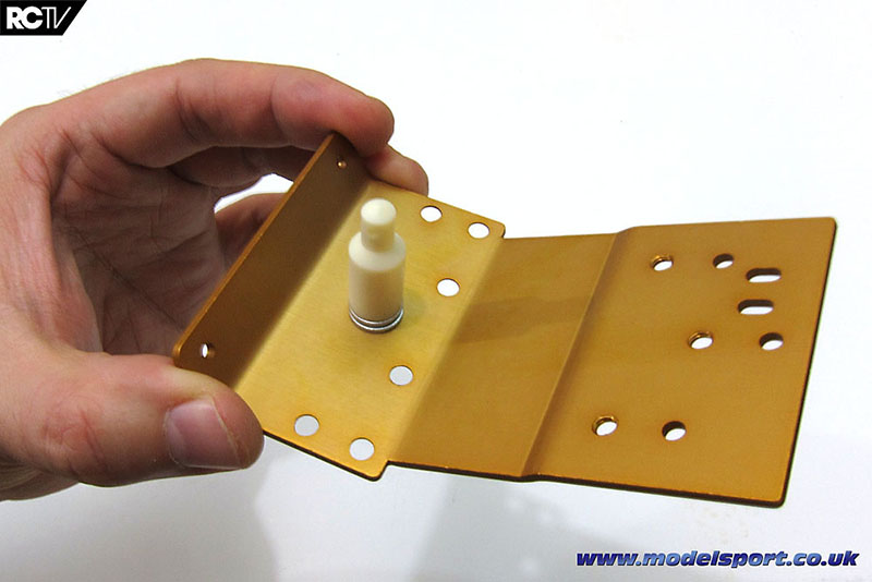
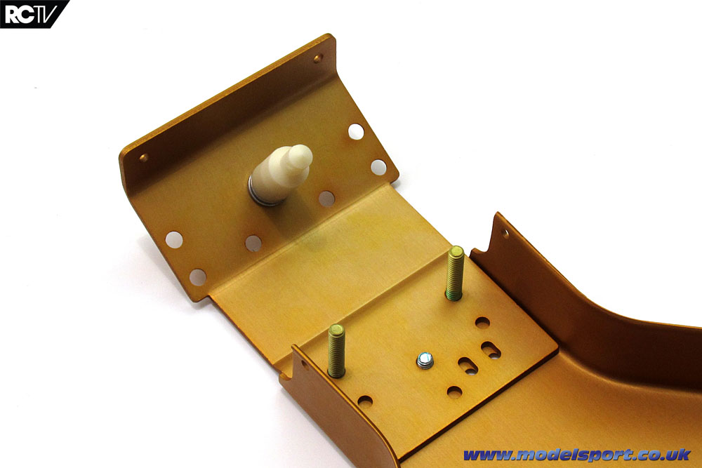
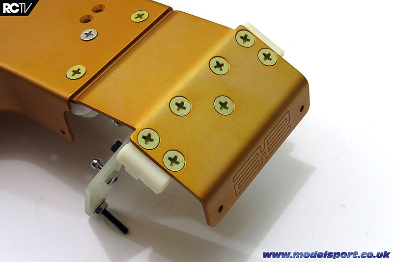
And we’re off! There’s the first part installed – the front body post! Woo-HOO!
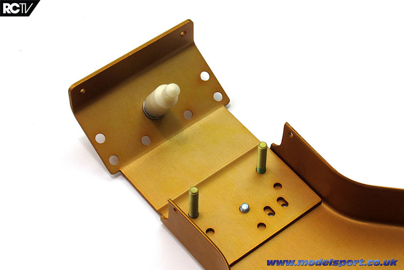
Attaching the nosepiece to the chassis – this is where I’ll hold my hands up and say I initially used the wrong size screws here, however referring to the parts size reference got me going in the right direction again. The manual tells you to use threadlock on these 3 screws, but it’s not included with the kit. I’m not sure if Associated include threadlock with their kits nowadays, but I did have to go digging around my toolbox to find some. I’m just used to kits that include a tiny tube of it! These modern racers and their expectations, lemme tell ya…

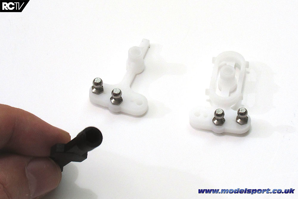
Here’s the steering arms with the ball ends attached. The kit includes this plastic wrench that works fine to install the ball ends into these soft plastic pieces, but I’m not holding out much hope for the rest of the kit… Be careful as the hex part of the ball end gets close to the plastic of the steering arms, because that wrench WILL start to strip out.
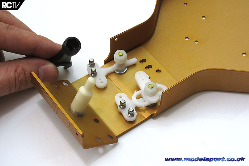
Installing the steering arms into the chassis. No ball bearings here! Just fit the nylon nuts and tighten them down with the wrench shown, then back off the nut a bit until you have about a half thread of the bolt showing. Check that the arms move freely back and forth and you should be fine.
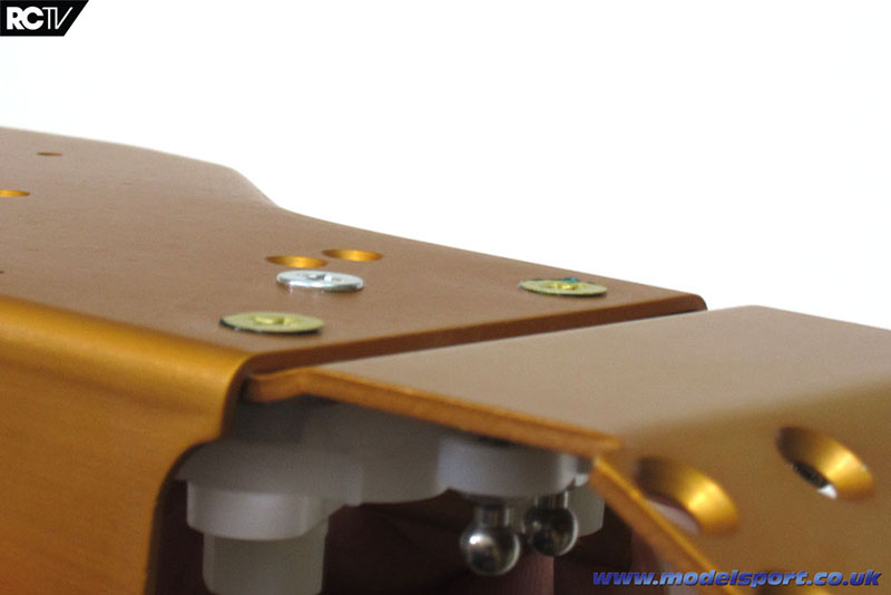
With all the steps completed, here’s what the underside of the chassis looks like for now – the screws aren’t completely flush with the chassis but they’re not going to snag on every bump in the ground, either.

Here’s how the steering arms look after installation – notice how much thread is showing.
And here’s the video showing the co;mpleted steps:
Next up, we start to attach the front suspension parts!
Front suspension

We are continuing with the kit build of the Associated RC10 Classic, carrying on with assembling much of the front suspension! Last time around, we showed you how the first steps of assembly went, complete with up-close pictures and even a video! So let’s carry on and keep truckin’ on with the rest of the front end.
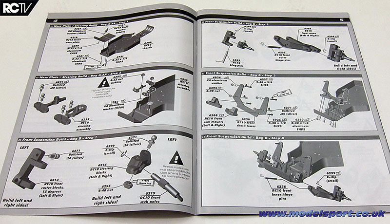
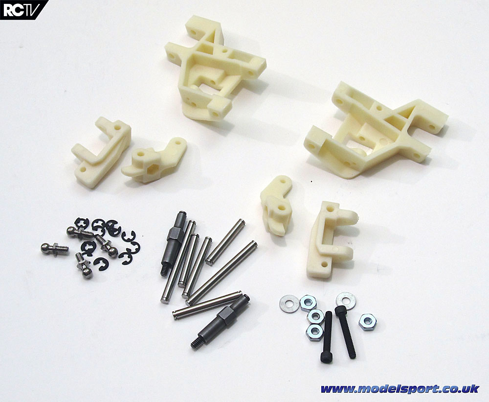
Bags B and BB are the next ones we’ll cut open – the parts are used in the next four steps, consisting of the third step at the bottom of the left page and all three steps on the right page.
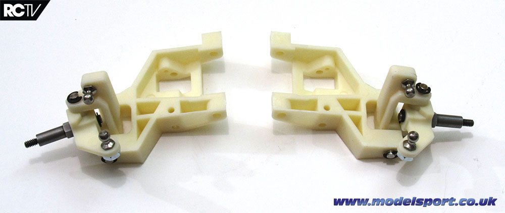
Here’s all the parts in the hardware bags – the bag contents are separated B1, B2 and B3. Bag BB consists of the plastic uprights, seen above next to the steering knuckles. All the remaining hardware from bags A and AA in the previous steps are used up in the next few steps.
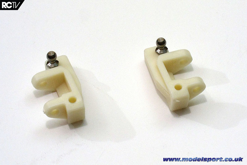
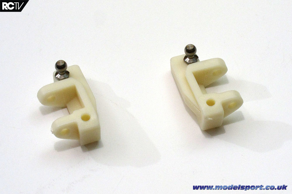
First things first, screw in the ball ends to the uprights. These aren’t labeled ‘L’ or ‘R’ so, you have to look carefully at the picture in the manual to see which way to install the ball end, because the mounting hole goes all the way through. In the picture above, though, the left upright is on the left and the right upright is on the…wait for it…the right!
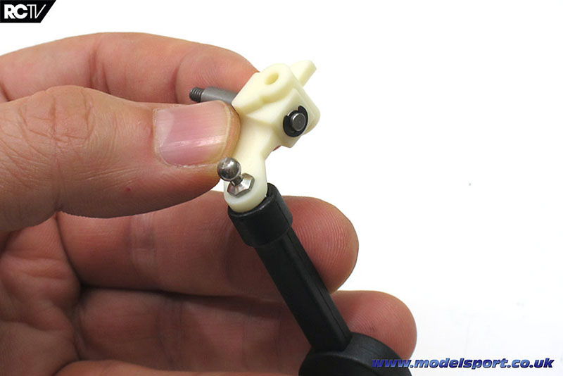
The steering knuckles take a couple of steps: you have to push down hard on the axle to get it through the plastic knuckle so the e-clip can be attached. The e-clip goes on fine with a flat-head screwdriver, but don’t lose any – you get exactly the number you need (ten) to do the front end, and that’s it. You need to make sure the ball ends go the correct way in, too, otherwise you’ll end up with two lefts or two rights. The ball end is screwed in with the wrench and then use the larger wrench to attach the nut on the opposite side.
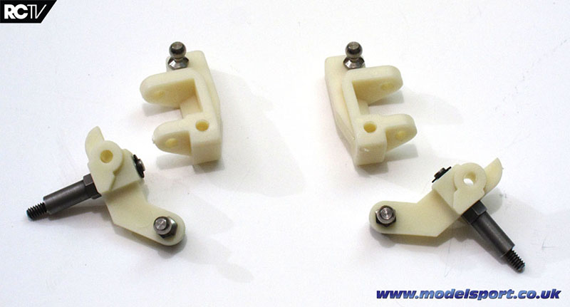
If you end up with mirror-image parts like these, you’ve done good so far! The uprights and knuckles are ready to be attached.

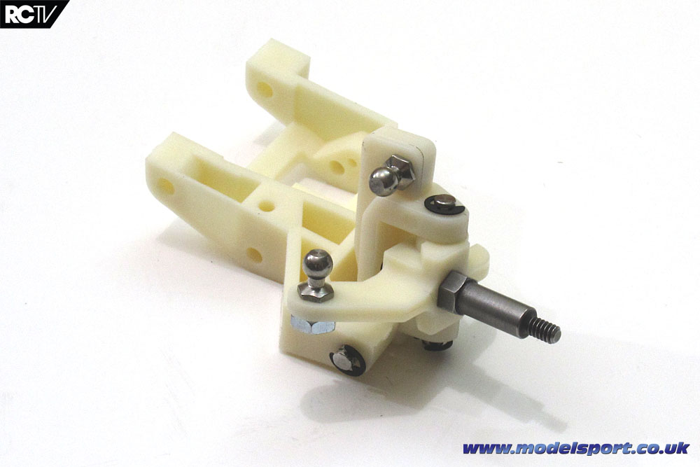
Here’s the right-side suspension after installing the kingpin (the upright pin) and the outer hingepin (the other pin), ready to be attached. Again, you get exactly the number of e-clips you need (no spares), so don’t let them go pinging off across the room, you’ll never find them! If you’re not used to attaching them without a specialist e-clip tool (like Tamiya’s e-clip wrench) hold the parts in a towel or spare T-shirt so if the clip springs off somewhere it hopefully ends up in your hand.
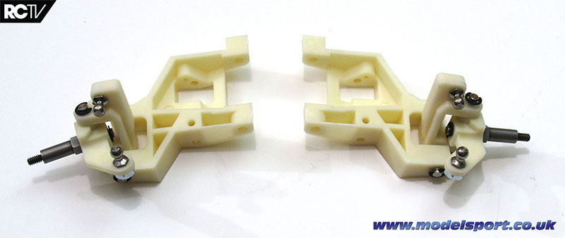
The left side and right side suspension pieces. The picture in the manual may confuse you when you’re trying to figure out which arm goes to which side, but look at the box photos if you have to (or just use this guide).
I have to point out that the outer hinge pin on the right side was an absolute bugger to fit through the hole in the upright. I actually had to gently force the hinge pin through before installing it properly, then I had to use a pair of pliers to get it out again – so another nasty-looking set of scratches on the end of the hinge pin. Not good! I’m pretty sure the holes in the upright are meant to be a tiny bit tighter than the holes in the arm, so the hinge pin rotates in the arm instead of in the hinge pin, but they are almost certainly not meant to be that tight.
In any case, a reamer through the hinge pin holes wouldn’t be a bad idea (assuming you have the correct size reamer or drill bit), and neither would polishing the hinge pins (securing them in a power drill and rubbing them in a rag with a bit of polishing compound). Polishing the pins is something I’ll probably do before I run the car properly.
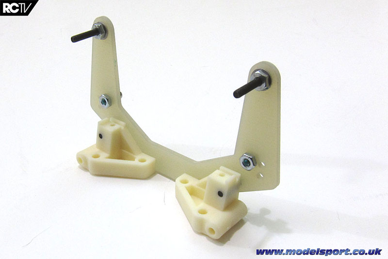
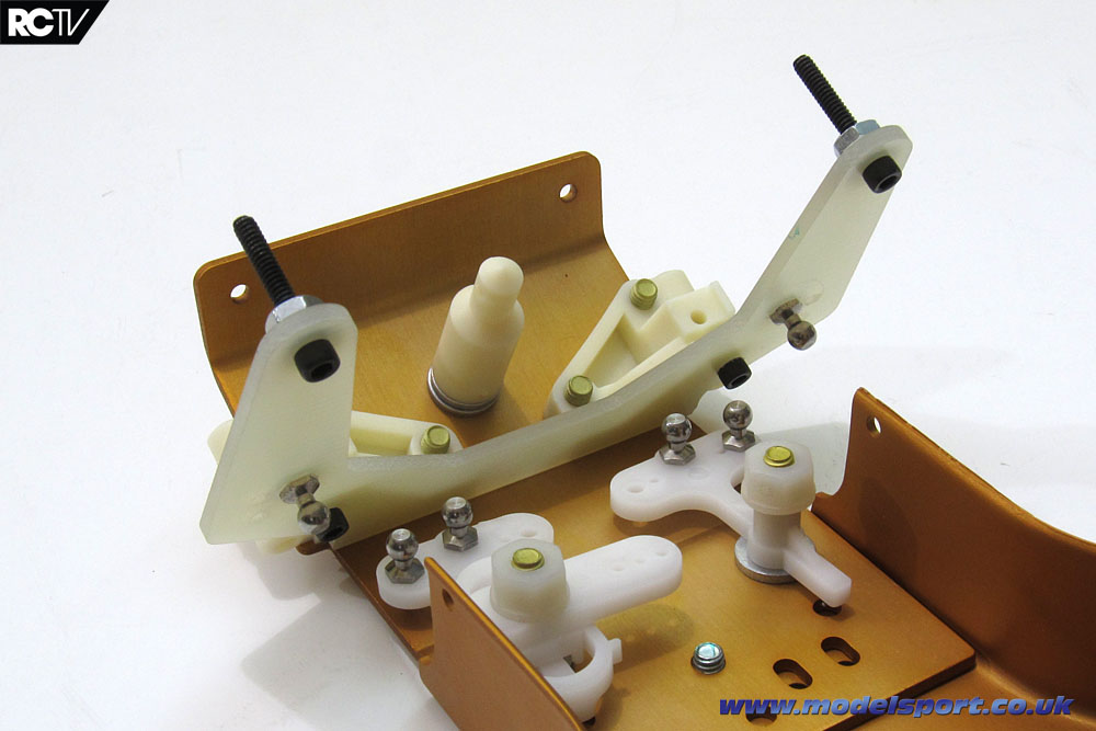
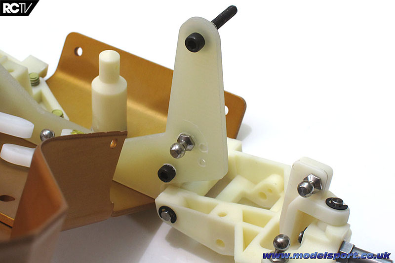
Here’s the shock tower ready to be installed. The black bolts need wrenches to go through the fiberglass, but they go in pretty easy, and the plastic ball endwrench finally gave out trying to screw the ball ends through the material – I had to use a pair of pliers to finish them off.Like in the last step with the hinge pins, I’m not sure if the original kit was this way when it was released, but it’s interesting that the kit is like this upon its re-release.
Here’s the front end after installing the shock tower…
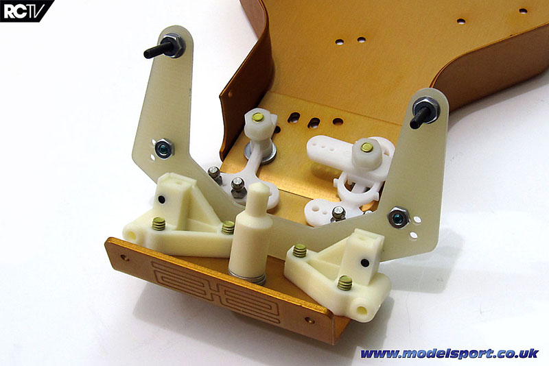
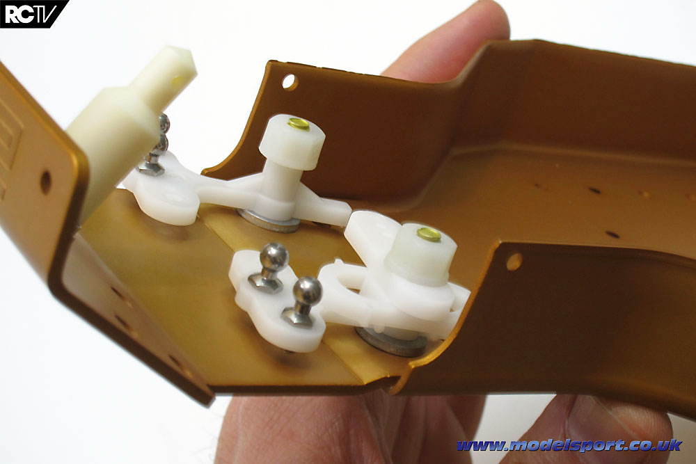
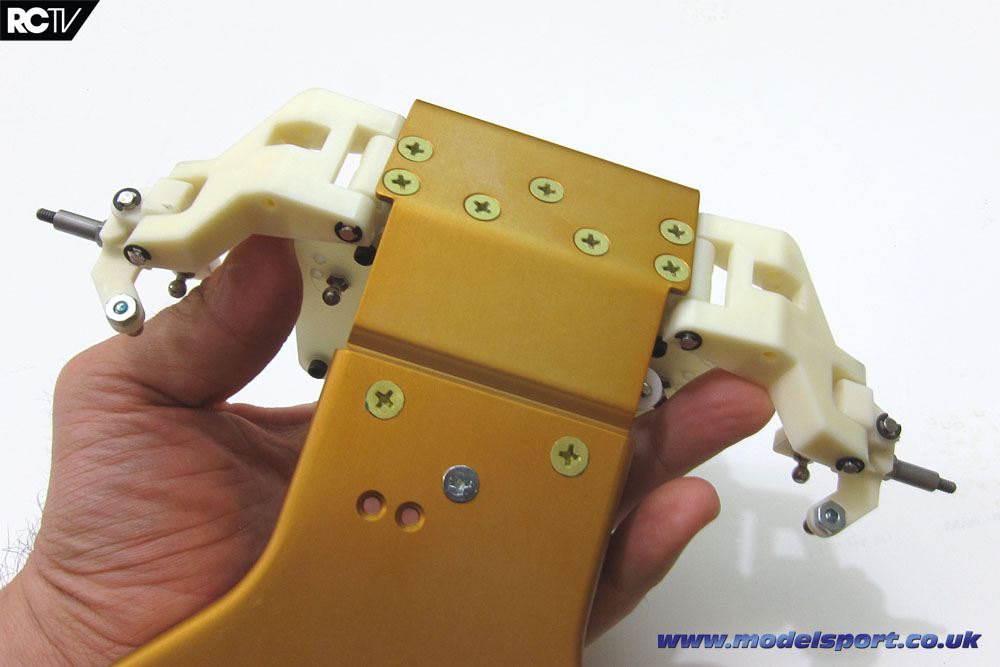
…and the topside view. All that cream-colored plastic and the gold chassis is starting to come together!
Another view of the assembly so far.
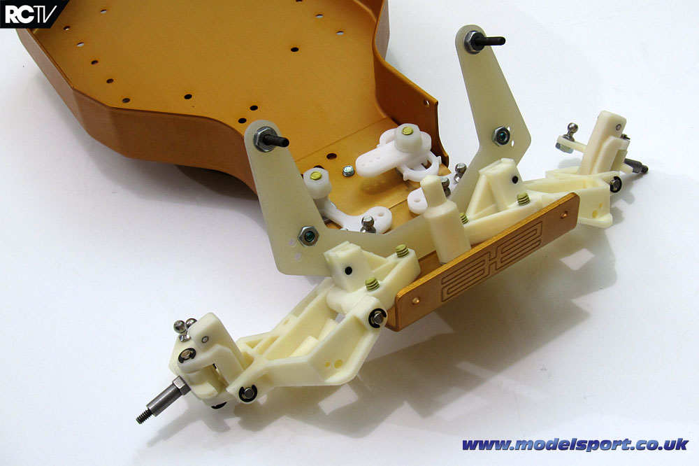
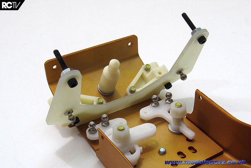
And the final step is attaching the arms with the inner hinge pins. The arms are heavy enough that they flop down easily enough, but the uprights and steering knuckles are a bit stiff still. It might be a little early to tell if they’ll free up after a couple of battery packs have been run through the car, but it still wouldn’t hurt to do the polishing trick on the pins.
There’s that scratch on the fiberglass around the ball end. I know it doesn’t affect anything and probably no one will see it but me after the car is fully built but I’ll know it’s there.
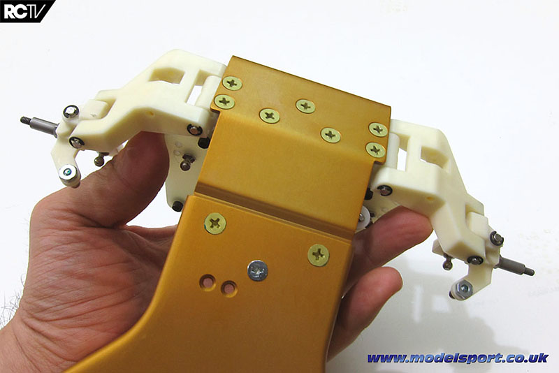
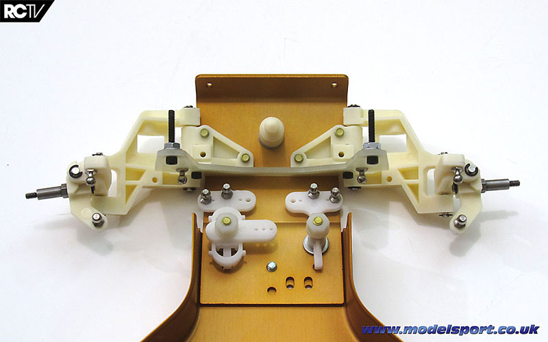
The underside of the car with the front bits attached. (I’ve always wondered why that one screw is the natural metal color instead of the gold-anodized color. I know the large gold screws are aluminum and that little screw is steel, but still. At least it’s centered and not off to one side – that would just set off my RC OCD!)

It’s starting to look like a car, eh?
Here’s the video showing how this series of steps went:
Well, we hope you enjoyed that!
Page 1 - Page 3
Source:

|