|
- Team Associated RC10 Classic - Build -
Page 2 - Page 4
Transmission Build
We are continuing with the kit build of the Associated RC10 Classic, carrying on with assembling the entire transmission! Last time around (see above), we showed you how the front suspension is assembled, complete with up-close pictures and even a video! So now I’ll be showing you how the rest of the kit goes together.
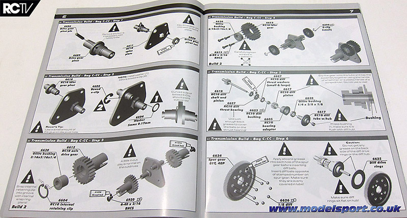
Here’s the steps we’re looking at…
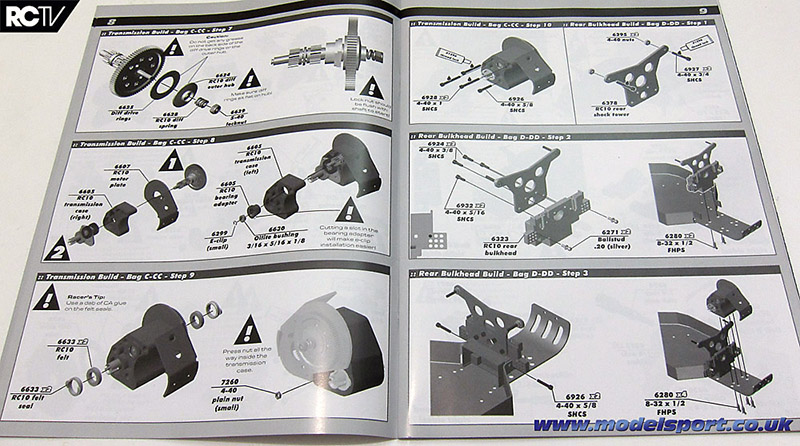
…and they’re spread over more than THREE pages!
But have no fear, it’s actually not that bad – let’s go!
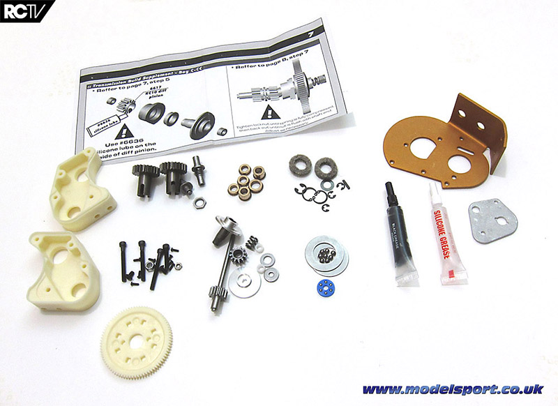
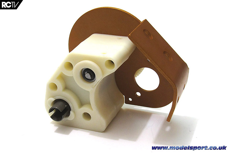
Here’s all the parts that are needed for these steps – Bags C and CC. Bag C are the bits on the left under the addendum sheet. The plastic transmission halves are in the main bag, and bags C1 through C7 are the hardware bits grouped together, plus the spur gear. Bag CC has the gold-anodized motor mount, greases and the gear plate that goes inside the transmission.
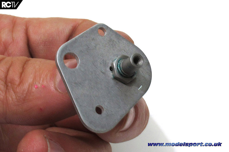
The first step is to attach a layshaft to the gear plate. This is another step where you need some threadlocking compound – don’t put too much on the threads, you don’t want any on the plastic gears you’ll be installing in a couple of steps.
Another layshaft, this one attaches with a funky large curved E-clip, which you may be able to just make out in the picture.
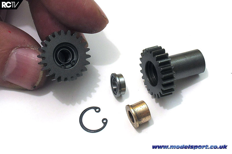
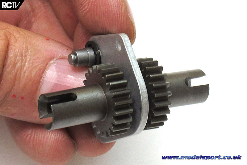
Now for the outdrives, or as some manufacturers call them the drive cups! Very interesting to see that the outdrives actually have gears directly on them. This is the first area of the transmission where we swap out the oilite bushings for the bearings supplied by Modelsport – look at how much rotating weight is being saved right there!
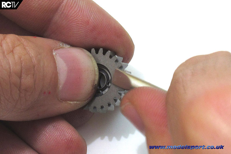
If you don’t have a C-clip wrench, don’t worry about it, just do as I did in the picture above and put a thumb securely over the C-clip and carefully use a flat head screwdriver to press it into place.
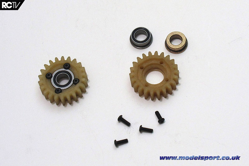
Now for 2 more gears of the 6-gear transmission – again replacing bearings for the bushings. These are held in place with four screws each – can you imagine putting this amount of rotating weight in a modern buggy transmission?!
So here we’ve got the outdrives installed on the lower layshaft…
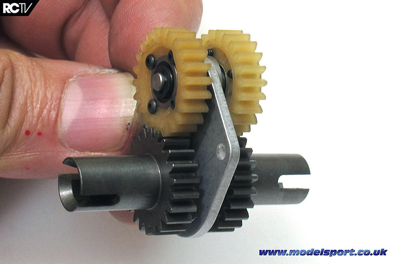
…and on the shorter layshaft we put the two plastic gears – it’s starting to coming together!
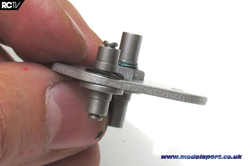
And now for the start of the thrust bearing and the final two gears. Handily, the thrust bearing is pre-assembled, which is quite nice.
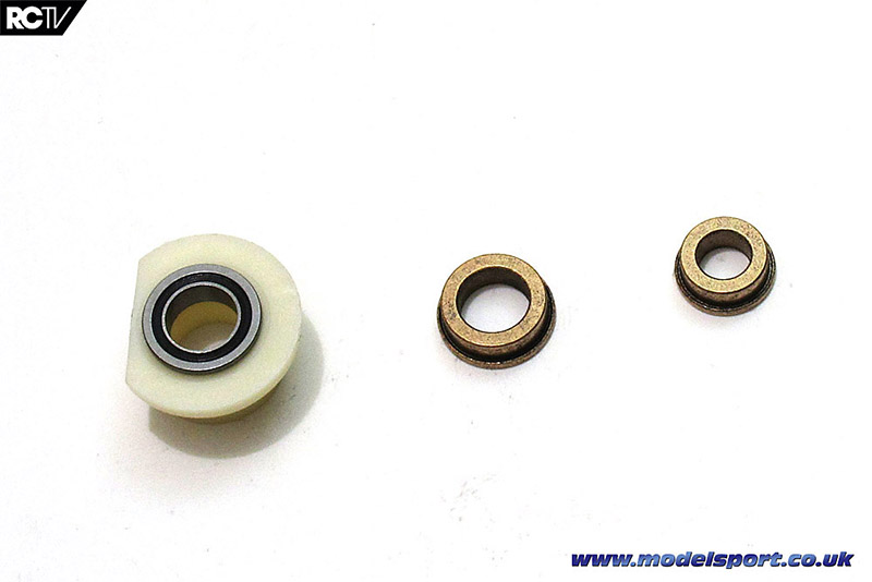
The thrust bearing set uses a couple of different sizes of bearings, so make sure you double-check the fit and placement. Unfortunately the manual doesn’t have a size reference for the bushings the way it does for the screws, so use a ruler or pair of calipers if you can’t spot the difference between 3/8? and 1/4?.
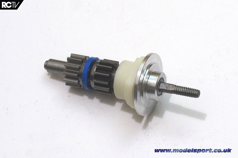
And here’s the completed thrust bearing set! One thing to note is to make sure you pay attention to the addendum sheet that’s stapled to Bag C, which tells you to lubricate the metal-to-metal surfaces – very important! If you forget to do this, you’ll have to disassemble the entire transmission to get to see this bit again…another area where you’d miss the modern convenience of today’s insanely easy to maintain drivetrains.
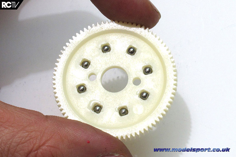
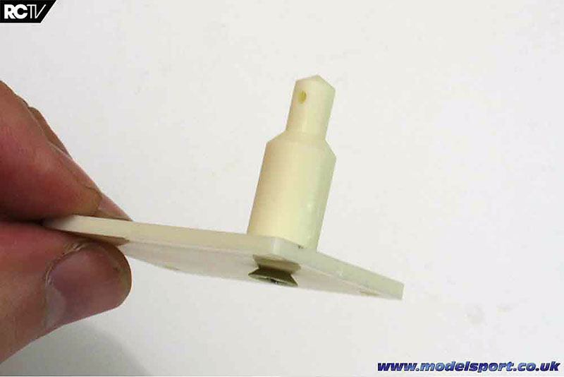
Silicone grease and 1/8? diff balls go into the spur gear easily enough!
Yes, that is an off-road buggy spur gear with diff balls, you’re not looking at a pan car spur!
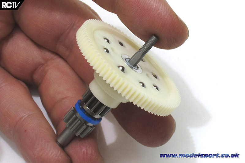
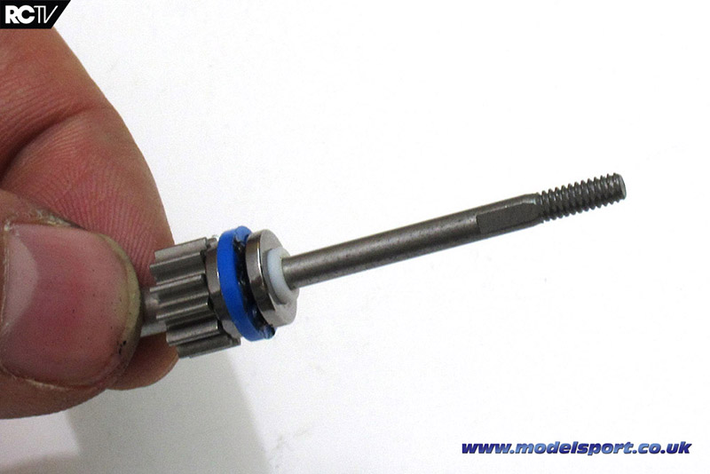
Then slide it onto the thrust bearing assembly.
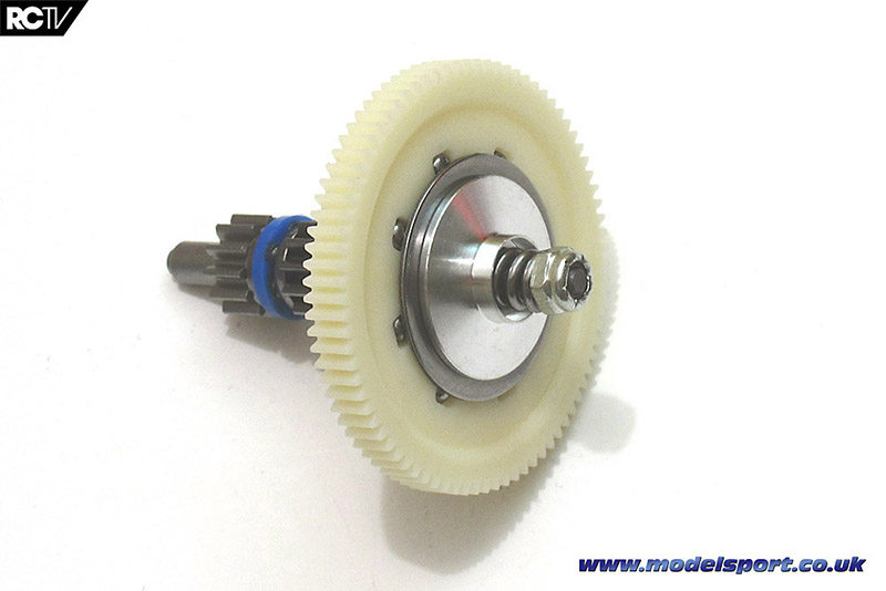
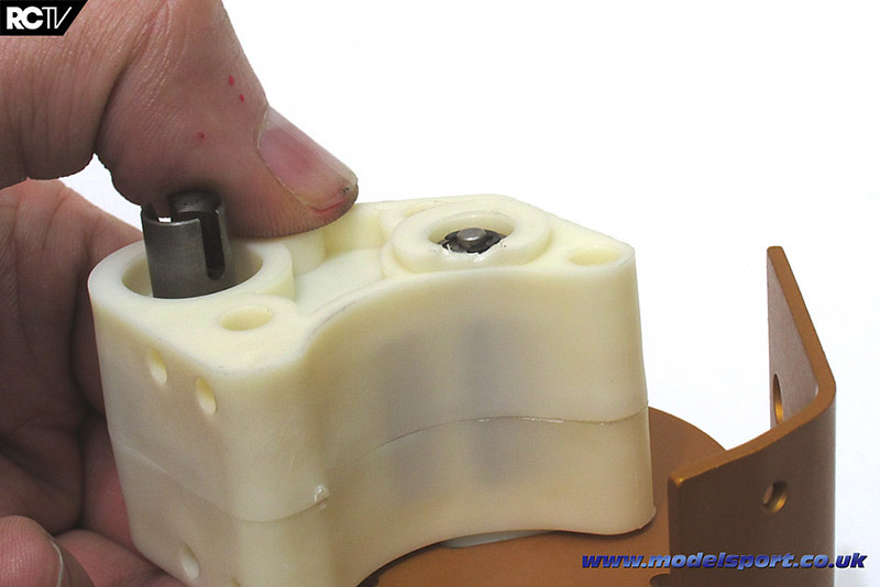
Compress the very small spring a couple of times with a pair of pliers, then secure it on with the locknut. Make sure the face of the locknut is flush with the end of the bolt.
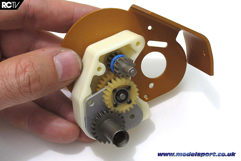
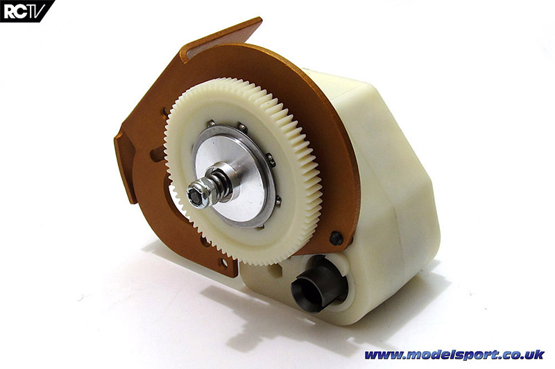
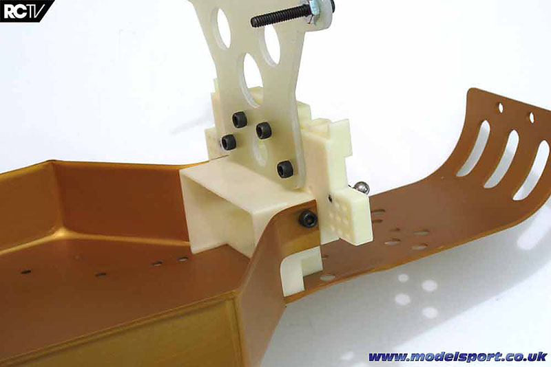
Now we slide the thrust bearing set through the motor plate and through the right side of the transmission case, meshing the gears with the assembly we made earlier. Here’s where you can see the guts of the 6-gear transmission all together for the first time. Again (and sorry for harping on this constantly, but it is a ‘retro’ kit!) it’s just amazing what modern car transmissions are like, with buggies having belts and instantly accessible spur gears and transmission adjustments. But hey this sucker won the Worlds, so who’s going to argue about the technicalities?
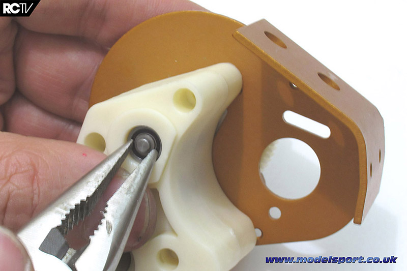
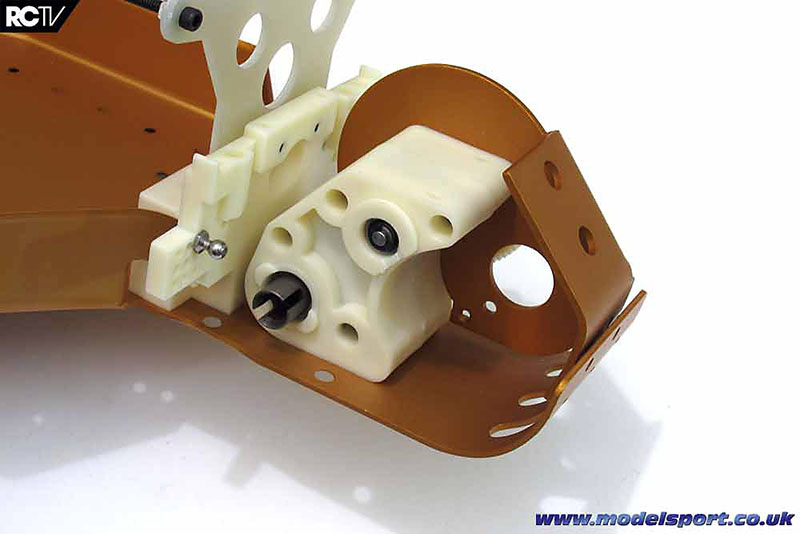
Attaching the e-clip on the end of the thrust bearing assembly – the clip holds in the bearing that supports the opposite end.
The manual suggests putting a notch in the case to make the e-clip easier to install, which is a good idea. I didn’t have to do this really but for getting the clip off the notch will definitely come in handy!
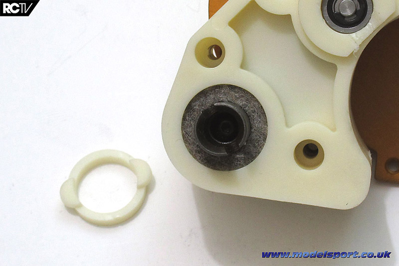
And now, installing the wool felt outdrive seals! Yes, wool. On a world championship-winning model car. Go figure! But hey, it does the job…and it’s sustainably sourced as well!
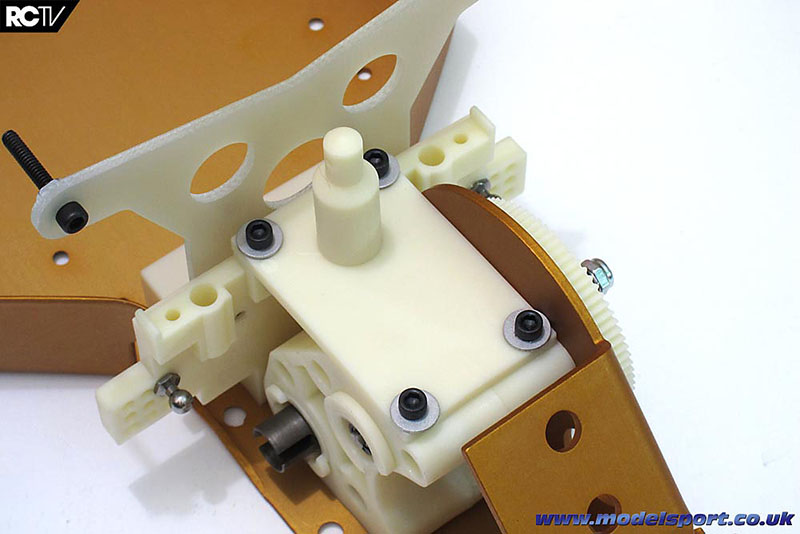
Attach the transmission to the motor plate with four bolts and job’s a good ‘un!
And there we go – the transmission is ready to install.
Now, here’s the video showing how all the steps went together:
Rear Bulkhead
As we carry on with the kit build of the Associated RC10 Classic, we move on to installing the rear bulkhead, shock tower and transmission on the chassis. In the previous installment (above), we showed you how the transmission went together, so let’s move on with the next steps: Bags D and DD!
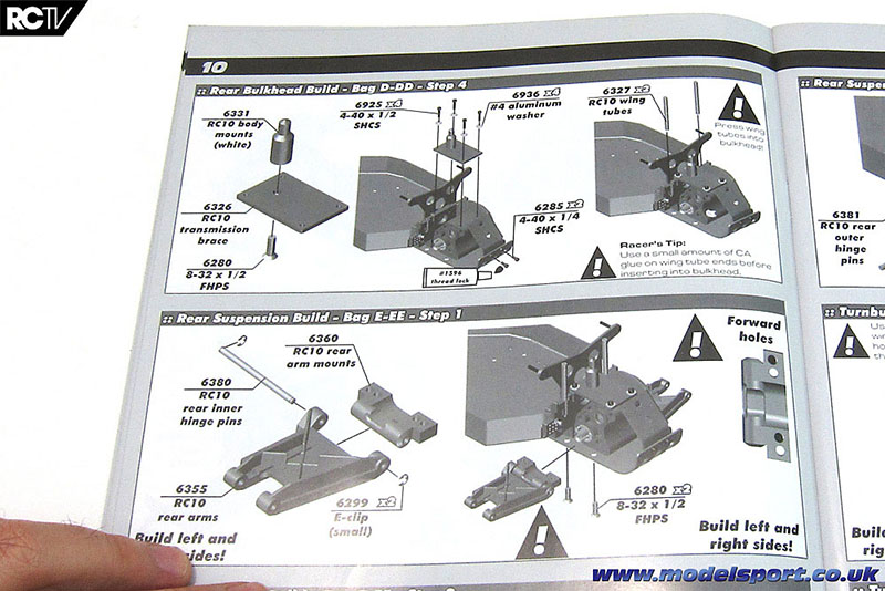
Here’s the steps in the manual…
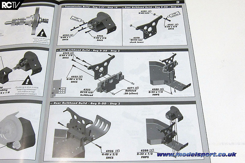
…not too much to do, really, and these steps go pretty quickly after dealing with the transmission.
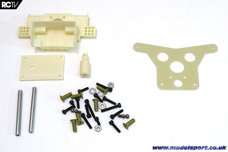
All the parts used in this step. Bag D has all the parts except for the shock tower (that’s in Bag DD) with the metal parts separated as shown in Bag D1 and D2.
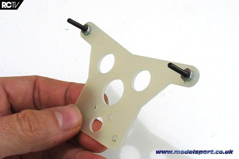
The first step is screwing the shock mount bolts into the place – again, you have to use threadlocking compound on the nut.
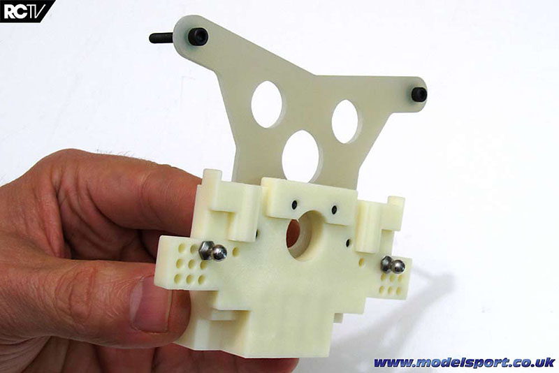
Then bolt the shock tower into place on the rear bulkhead. Make sure to measure the bolts you’re using in this step to make sure you’re using the right ones! I encountered a problem here in a later step (which will be posted soon). The ball ends also go into the correct camber mount locations at this point.
Now the rear bulkhead is put into place. Two more of the large screws on the bottom…
…and one 4-40 bolt on each side.
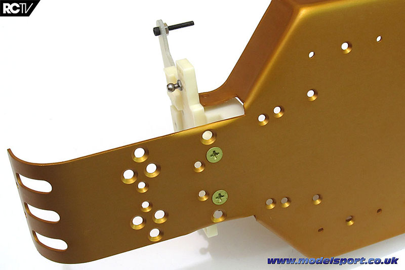
Now the transmission is installed, using more of the large gold-anodized screws.
The rear body mount is installed on the transmission brace.
Then the brace is installed, using 4 bolts.
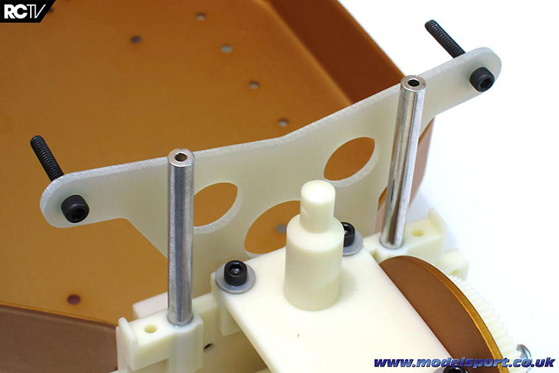
Finally, the wing posts are inserted into the bulkhead. They do take a bit of persuasion, and the manual actually tells you to use a bit of CA glue to make sure they stay in place.
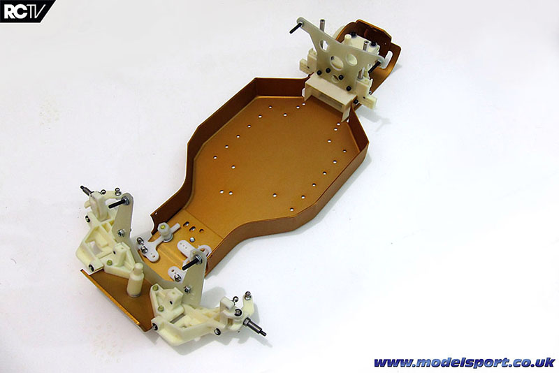
And that’s it for Bag D and DD! Here’s the car build so far – ready for the drivetrain, shocks and electronics.
Now, here’s the video showing how these steps went together:
In the next installment, we finish off the drivetrain!
Turnbuckles
We carry on with our review of the Associated RC10 Classic kit build! In the previous step, we showed how the rear suspension arms and driveshafts went on the car, and this next step, Bag F we build the camber and steering links. It’s not pleasant but at least it’s a quick series of steps, and it must be done…The goal with this step is literally to just power through it and forget it ever happened. On we go!
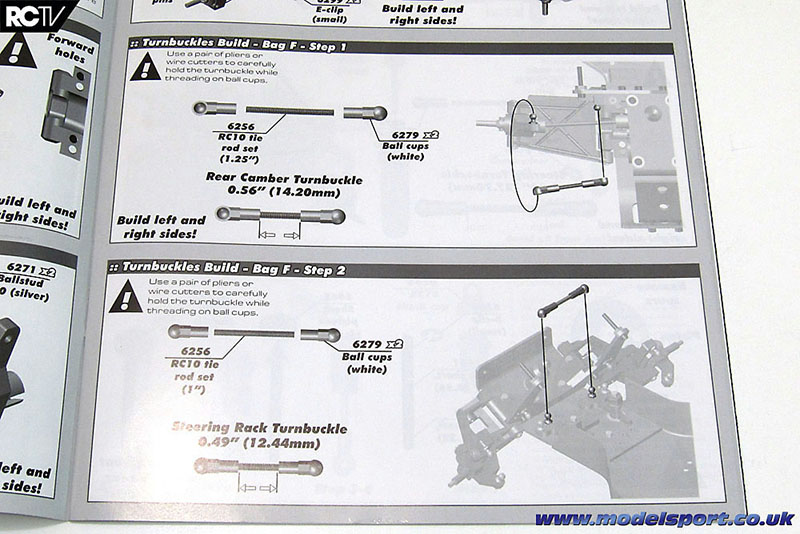
There’s only 4 steps to the turnbuckles, and here are the first two! First up is the rear camber link, then the single drag link for the steering.
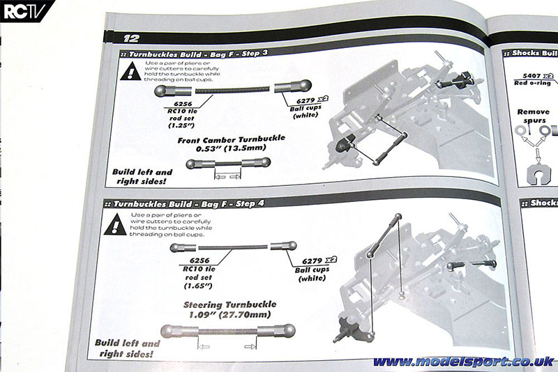
Then comes the front camber links and finally the steering links.
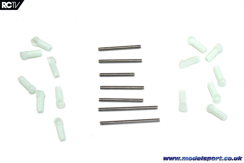
Here are all the parts used in these steps – I’ve arranged the threaded rod in the order that the steps call for them, so do the same thing and you’ll know which lengths of rod go in each step.
The rear end links go on first, and assembly of the ball cups onto the threaded rod was about as tedious and painful as I’d expected. The RC10 Classic is supplied almost exactly as it was when it was first released – remember no threadlocking compound? – so there’s no ball cup wrench like you get in self-assembly kits these days.
I used a pair of wire cutters to hold the threaded rod (you can see the marks in the middle of some of the turnbuckles) and started twisting on the ball cups by hand, which got really tiring after about the first ball cup. By the 14th ball cup, I was using a towel to keep the pain from crippling my thumb and forefinger. Why didn’t I use a pair of pliers? Well, part of me was trying to get it built ‘old-school style’ (before I had proper tools) and also I couldn’t find my second pair of needle-nose pliers.
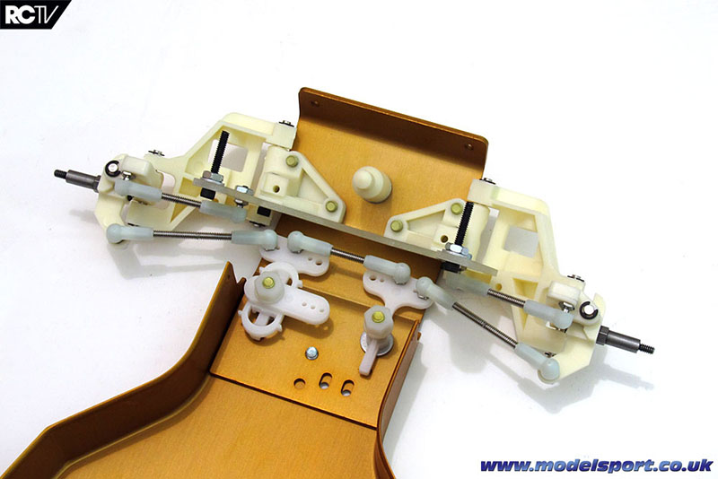
The front end gets 5 links all its own, that’s 10 ball ends to wrangle on. Ugh! Seriously. Just painful.
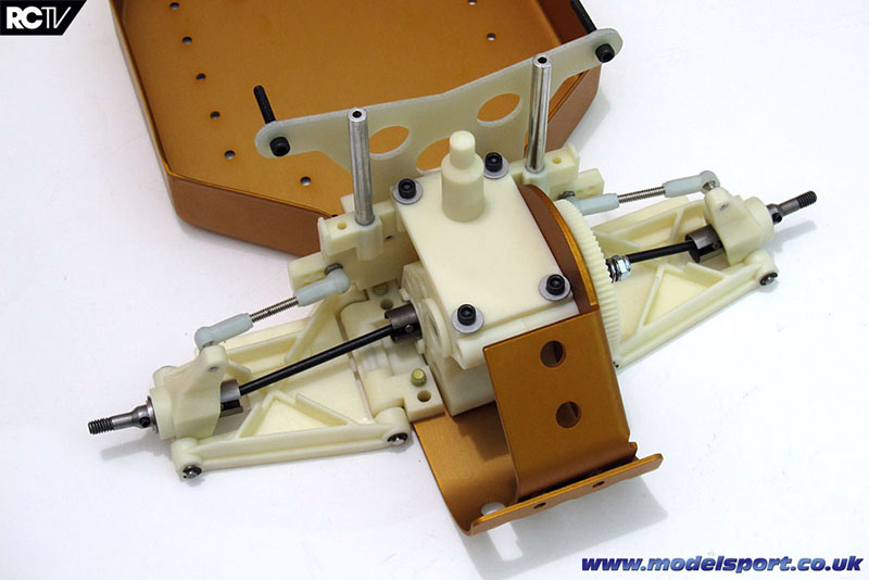
Well, we’re getting there! The car is really starting to come together with the front and rear suspension nearly completed!
Here’s the video showing how this step went:
In the next step, we assemble the shocks… which provides us another lesson in how far RC car tech has come in the last 30 years!
Page 2 - Page 4
Source:

|


