|
- Team Associated RC10B6D 2WD Buggy Build - Steering & Servo -
Intro Page
The Build – Part 1
The Team Associated B6D uses a standard dual-bellcrank steering system that rolls on high-quality bearings. A few refinements have been made to make it easier to build and smoother on the track. I like the new front bulkhead that separates the shock tower and the camber link as well as the side rails that replace the muliple molded pockets.
Build Notes:
▶ In Step 3, pay close attention to the direction of the steering bellcrank brace. The through-holes have a small lip on them – this lip needs to face the bearings to ensure you don’t bind the system when tightening down the screws.
▶ In Step 6, the manual calls out 4 10mm screws and 6 8mm screws. They’re not all marked in the manual which isn’t a big deal, but it did take me a second to think it through which screws are which. I’ve outlined it a little better.
▶ In Step 7, do not tighten the screws holding the servo to the mounts. There needs to be a little wiggle room until you mount the servo to the chassis – then tighten up the screws.
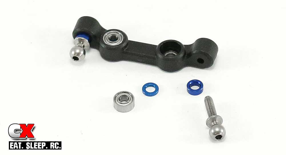
The first step is to install the bearings and ballstuds into the steering rack. Pay close attention to the orientation of the rack, both the top and the front. Press the bearings in with the blue 1mm washer in between. Install the ballstuds and include a 2mm washer.
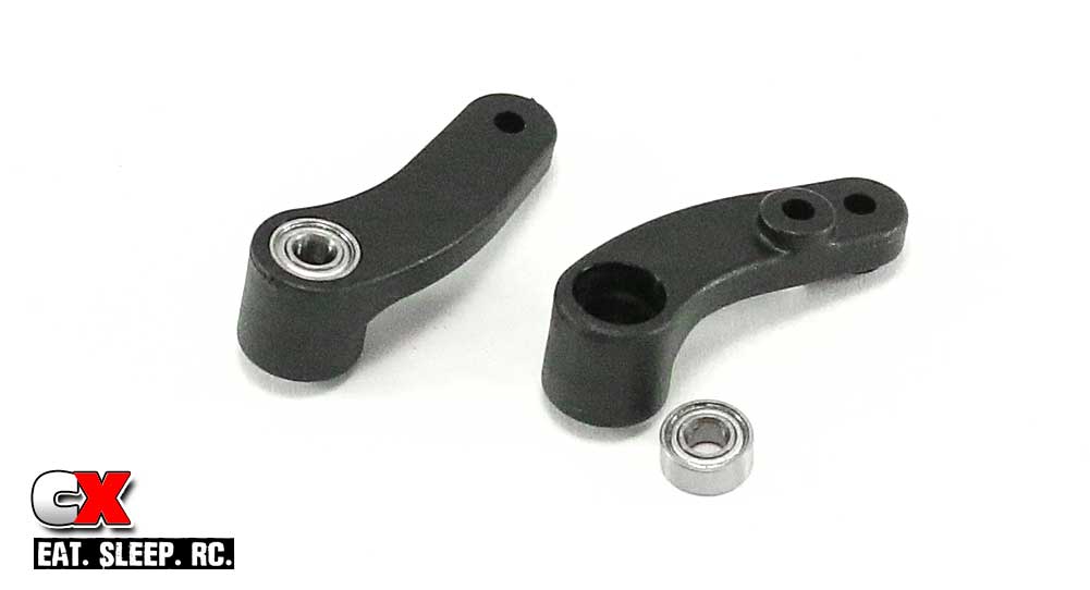
Press the bearings into both of the bellcrank arms.
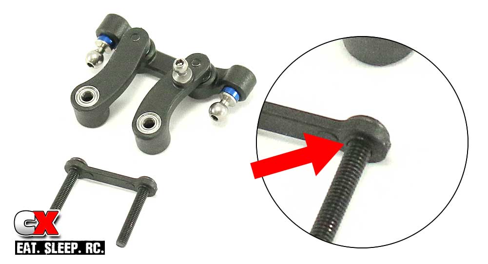
Attach the bellrank arms to the steering rack as shown (note the orientation). Slide the two 20mm screws through the steering bellcrank brace, making sure the small lip is facing down.
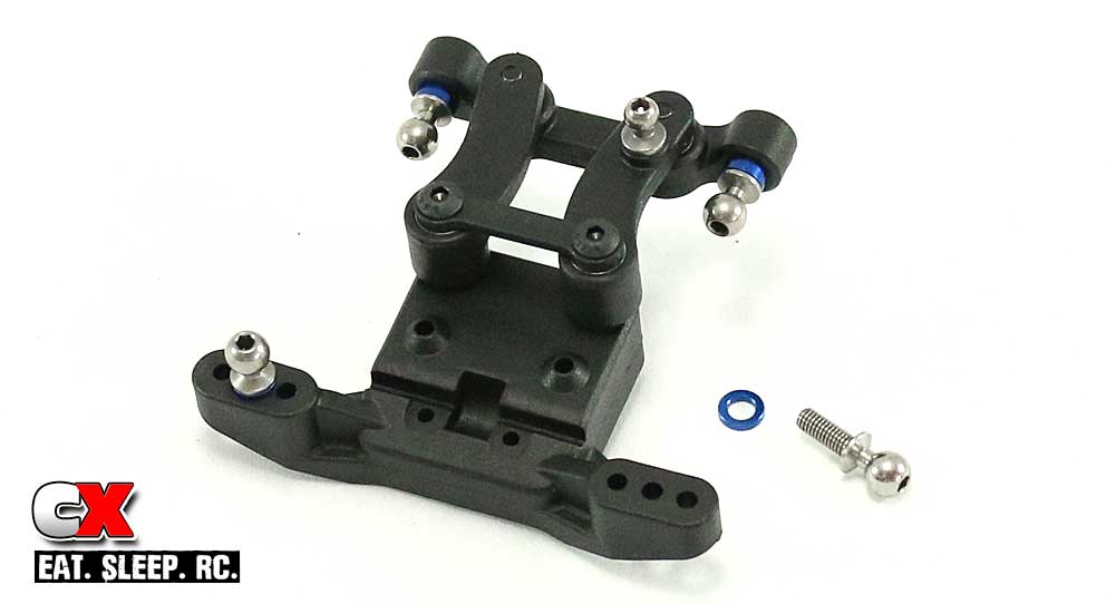
Attach the steering assembly to the front ballstud mount. Do not overtighten – you want the steering to swing freely with as little slop as possible. Insert the ballstuds into the middle hole in the ballstud mount. Don’t forget your 1mm washers.
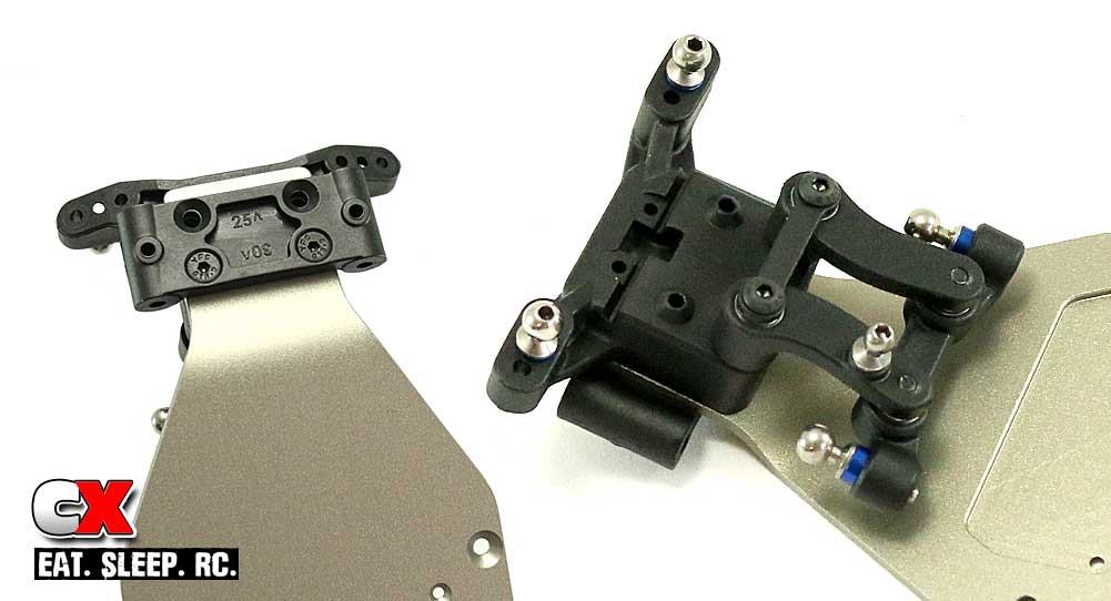
Grab the front bulkhead and note the numbers on the bottom; 25° and 30°. We want the 25° setting for the kit setup; make sure it is facing forward during assembly. Flip the chassis over and slide the two 16mm screws through the front bulkhead, then through the chassis. Flip the chassis back over and screw the 16mm screws into the steering/ballstud mount assembly.
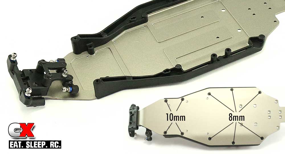
Attach the left and right side rails to the chassis. Note the screw locations for the 8mm and 10mm screws.
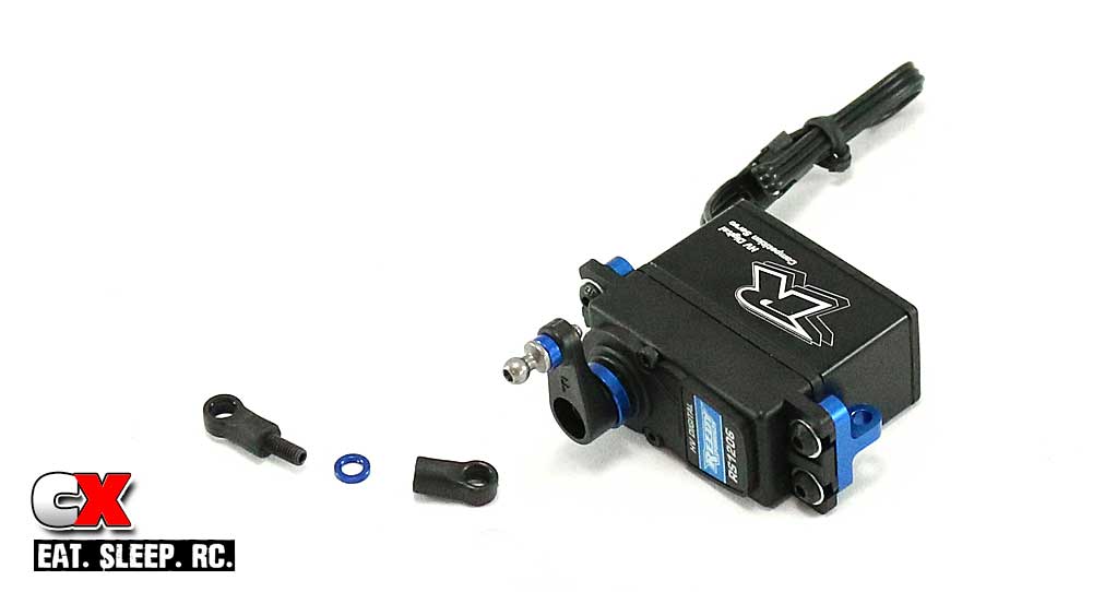
Team Associated includes four servo horns to fit a wide selection of servos. Since we’ll be using a Reedy servo, it uses a 25-spline horn, similar to a Futaba (F). Slide the servo horn ring over the Futaba horn, install the 8mm ballstud and mount to the servo. Attach the two aluminum servo mounts as well, but do not tighten them all the way down just yet. Finally, build and attach the drag link.
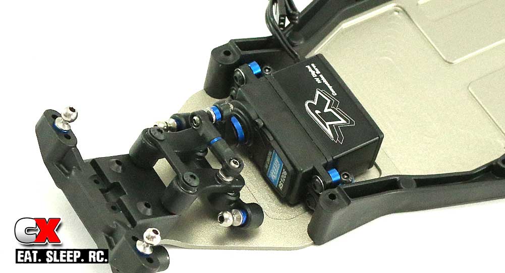
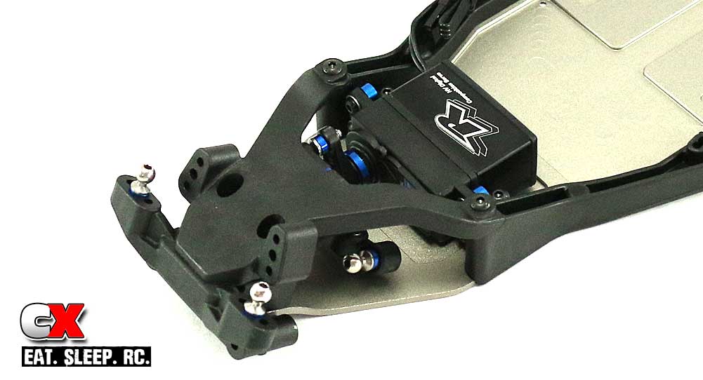
Attach the servo assembly to the chassis. Leaving the aluminum servo mounts loose allows us to space them to match the mounting holes. Once you’ve attached the servo, tighten down the four servo mount screws.
Attach the top plate to the chassis.
There you have it – the steering is done. Time to move on to the front suspension!
|
