Since your electronics will probably not match what I have, I left the install of these out of the build. It’s pretty straightforward, however, so you shouldn’t have a problem installing yours.
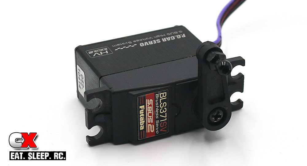
Step 1: The first step is to assemble the servo horn and attach it to the servo. You can use the included servo saver setup or, like I did, attach a standard horn. I’m not to keen on the Tamiya servo savers – they seem to flex a bit too much for me.
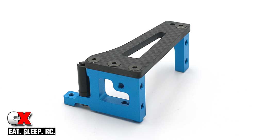
Step 2: Assemble the servo mount. Blue threadlock is suggested here.
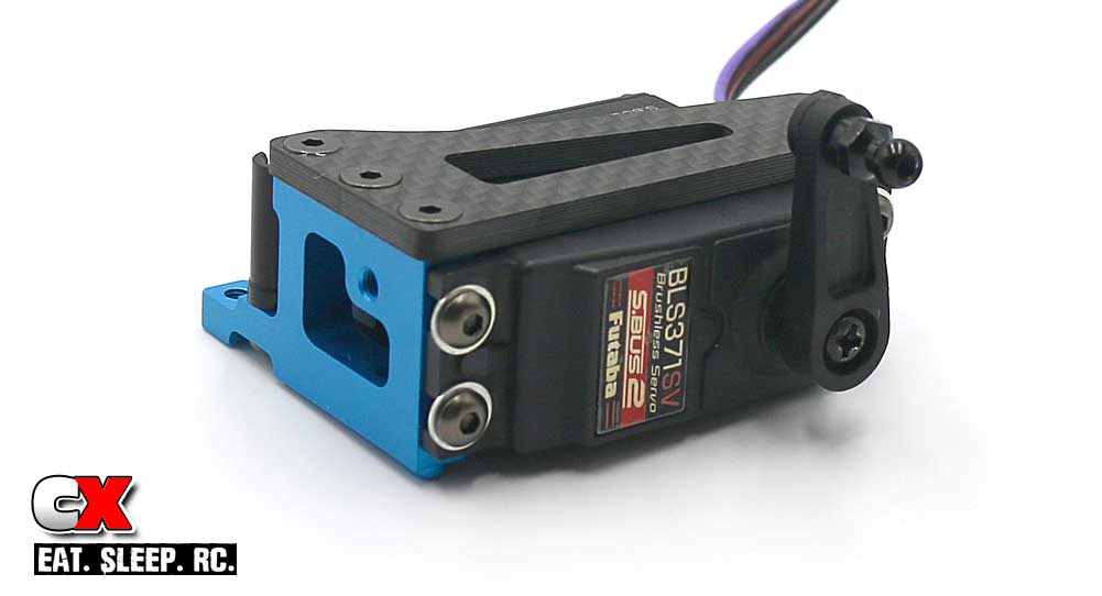
Step 3: Attach the servo to the mount. Again, Blue threadlock is suggested here as well.
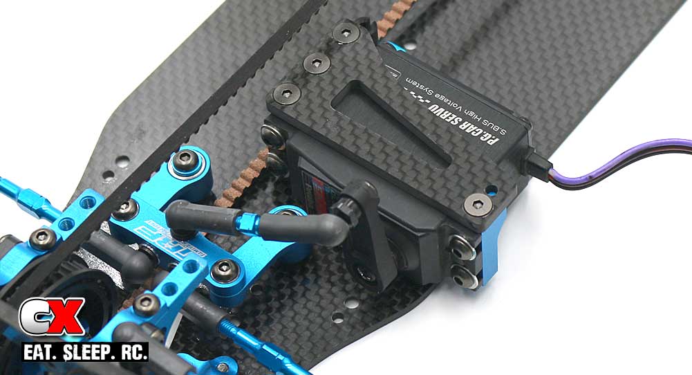
Step 4: Attach the mount to the chassis. You’ll notice it’s only attached on one side – this is an example of a floating servo mount. This helps retain the correct tweak on both sides of the car. Don’t forget to pop the drag link onto the servo horn.
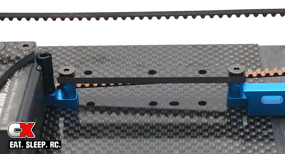
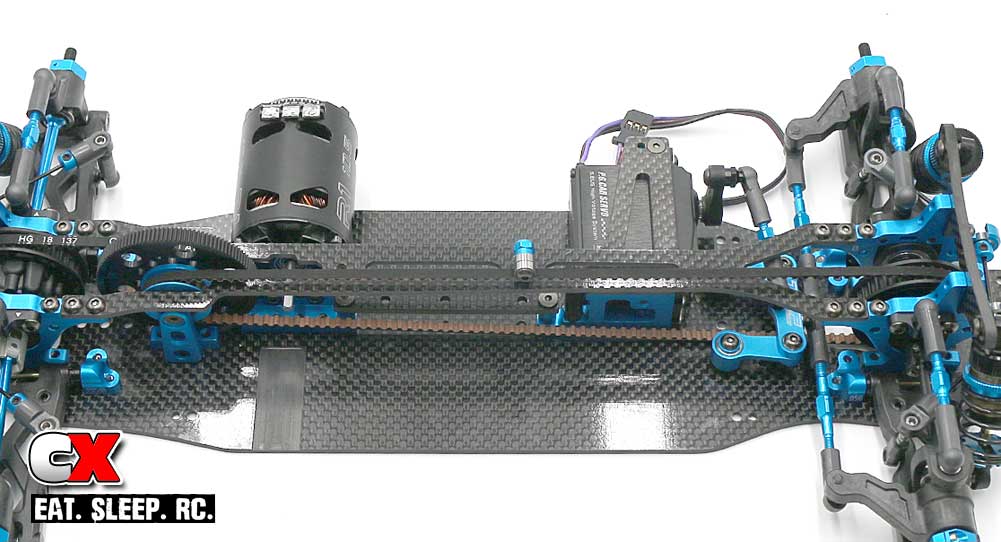
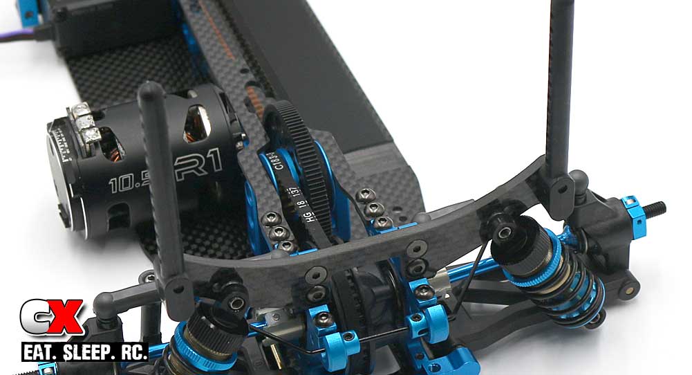
Step 5: Here is where you’ll have some options; I went with the carbon brace as a starting point. I also attached the weight in the center, however I chose to do it after I had already built the car. (See the end of the manual for chassis rigidity options).
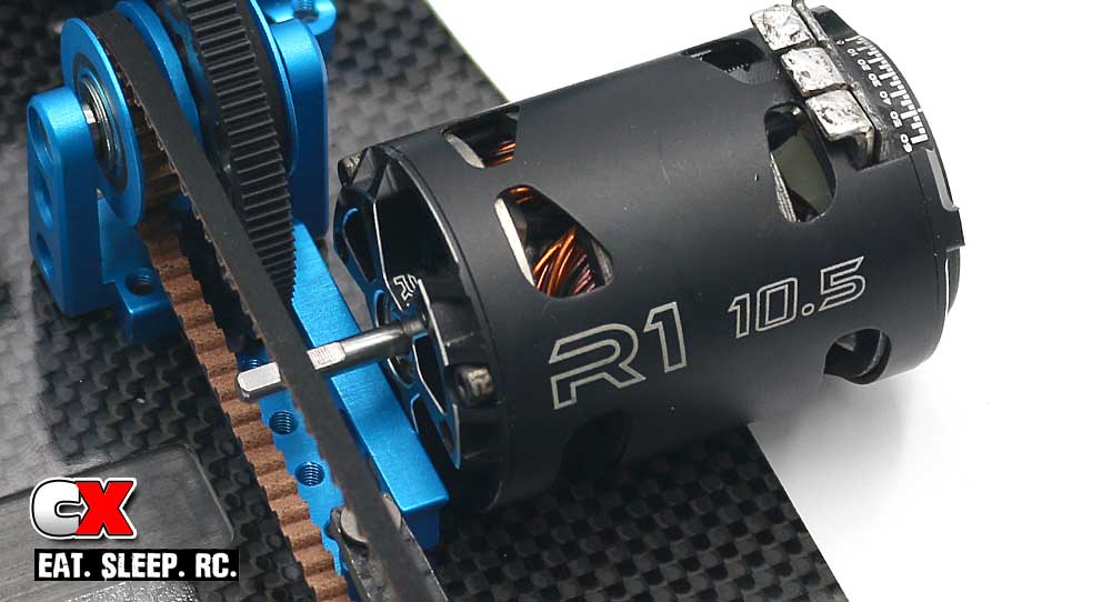
Step 6: Attach the motor. I will be running in the 17.5T class but, since my motor hadn’t arrived at the time of the build, I dropped a R1 Wurks 10.5T in for show.
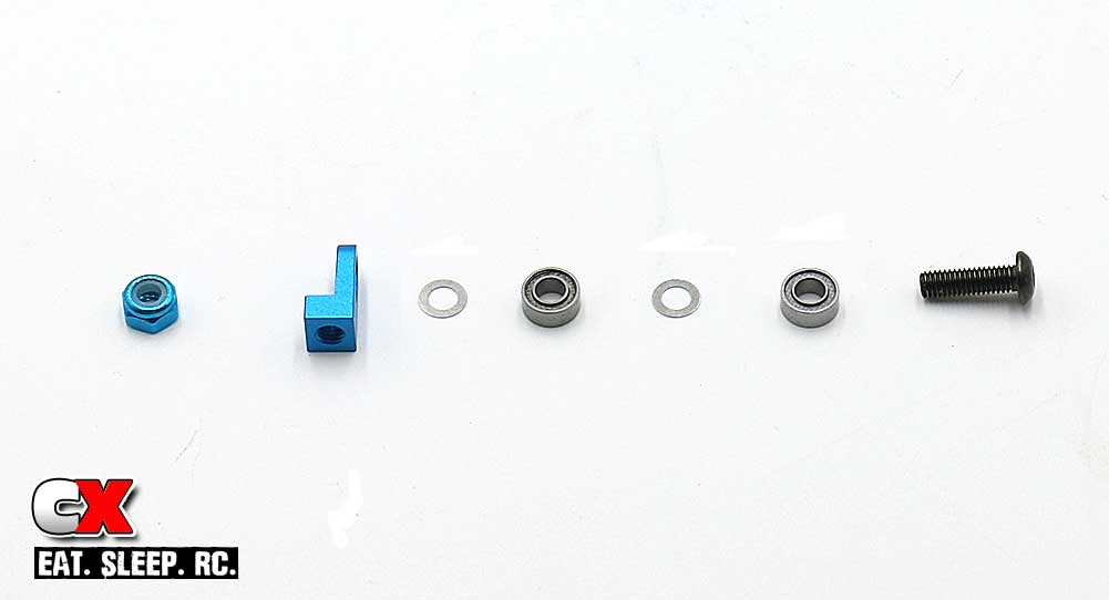
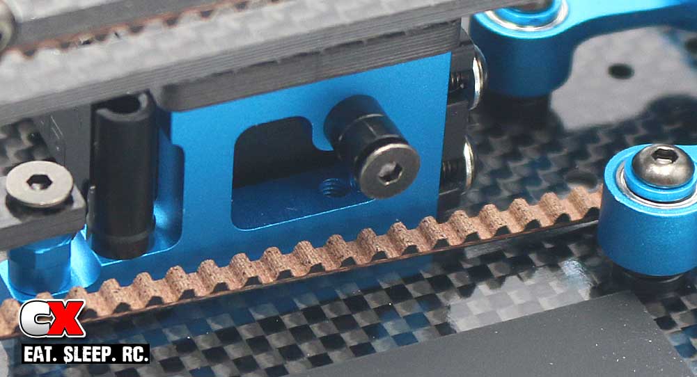
Step 7: Assemble the belt tensioner.
Step 8: Attach the tensioner assembly to the top deck.
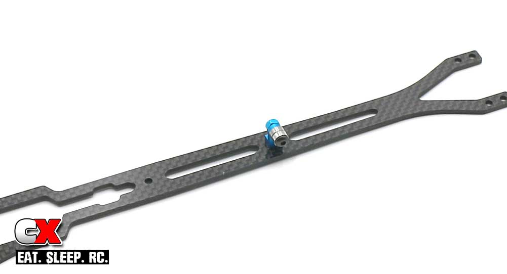
Step 9: Attach the top deck. I would NOT recommend using blue threadlock on these screws.
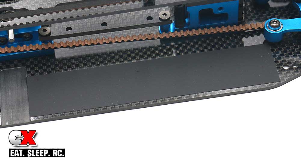
Step 10: Attach the battery pad. It’s a bit long so I cut it down a little to fit.
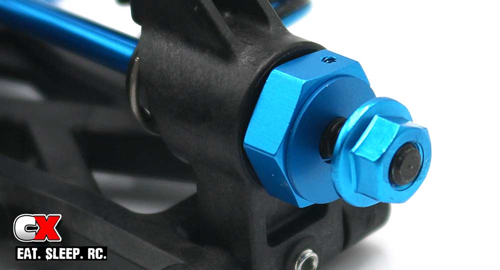
Step 11: Slip a wheel spacer onto the axle followed by the serrated nut. The spacers can be left off to help tune the width of your TRF419XR.
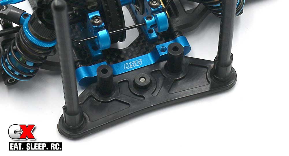
Step 12: Attach the rear body posts.
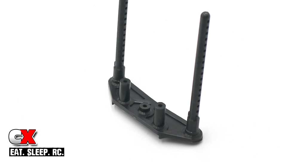
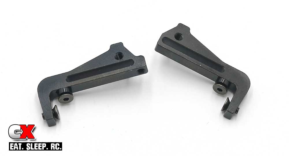
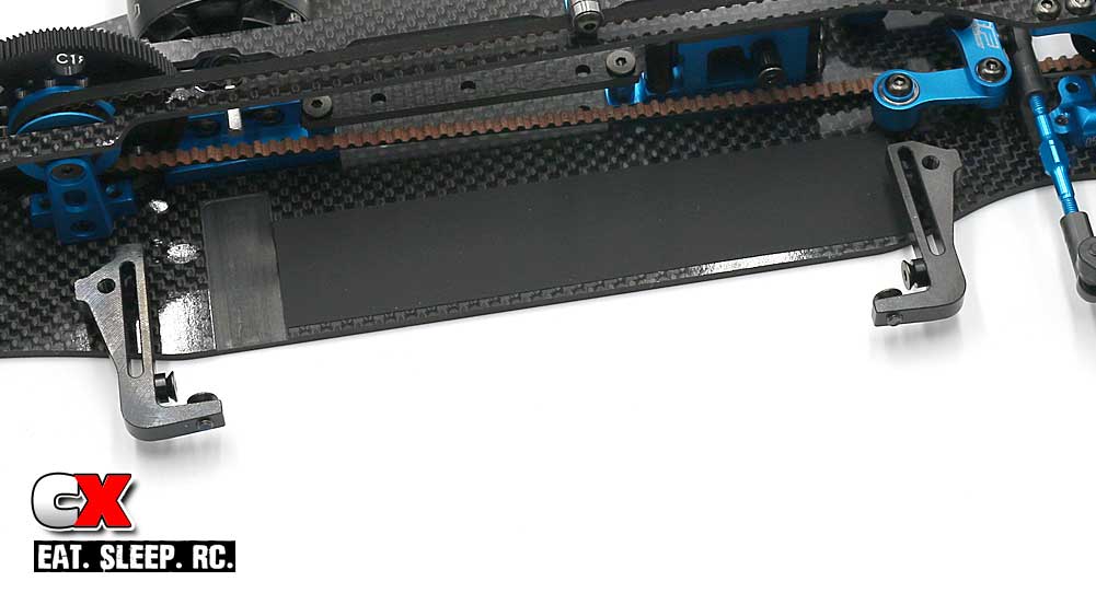
Step 13: Attach the front body posts to the front bumper.
Step 14: Attach the front bumper assembly to the chassis.
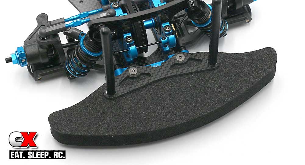
Step 15: Slide the foam bumper into place, then the carbon bumper mount. Secure with the 2 8mm screws.
Step 16: Install the battery bumper. This can be adjusted (more or less spacers) to move the battery in or out.
Step 17: Assemble the 2 battery holders. These additional screws can be adjusted (more or less spacers) to move the battery in or out or front to back.
Step 18: Attach the battery holders to the chassis.
And, just like that, you have a completed Tamiya TRF419XR Touring Car! Now install your electronics, mount that body and get to some racing!
Use the links below to follow each step.
Tamiya TRF419XR Touring Car Build – Opening Page
Tamiya TRF419XR Touring Car Build – Part 1 – Chassis/ Bulkheads
Tamiya TRF419XR Touring Car Build – Part 2 – Rear Differential
Tamiya TRF419XR Touring Car Build – Part 3 – Driveline
Tamiya TRF419XR Touring Car Build – Part 4 – Steering
Tamiya TRF419XR Touring Car Build – Part 5 – Suspension
Tamiya TRF419XR Touring Car Build – Part 6 – Anti-Roll Bars
Tamiya TRF419XR Touring Car Build – Part 7 – Shocks
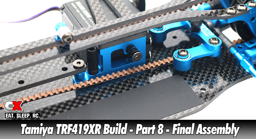
Tamiya TRF419XR Touring Car Build – Part 8 – Final Assembly