|
- Team Losi Racing 22 2.0 - Horizon Hobby - Build -
Steering & front end
Previous - Page 2 - Next
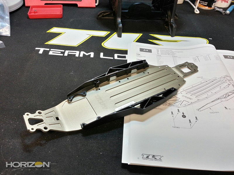
Time to get to building!
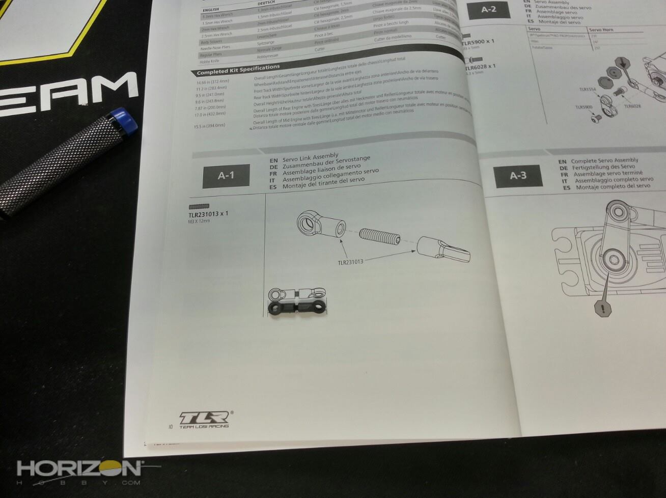
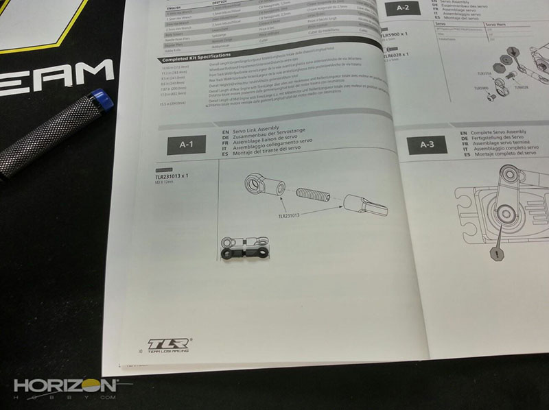
The first step is to build the drag link between the servo and the slider rack. I use a little bit of Black Grease on the threads to make it easier to thread into the molded cups.
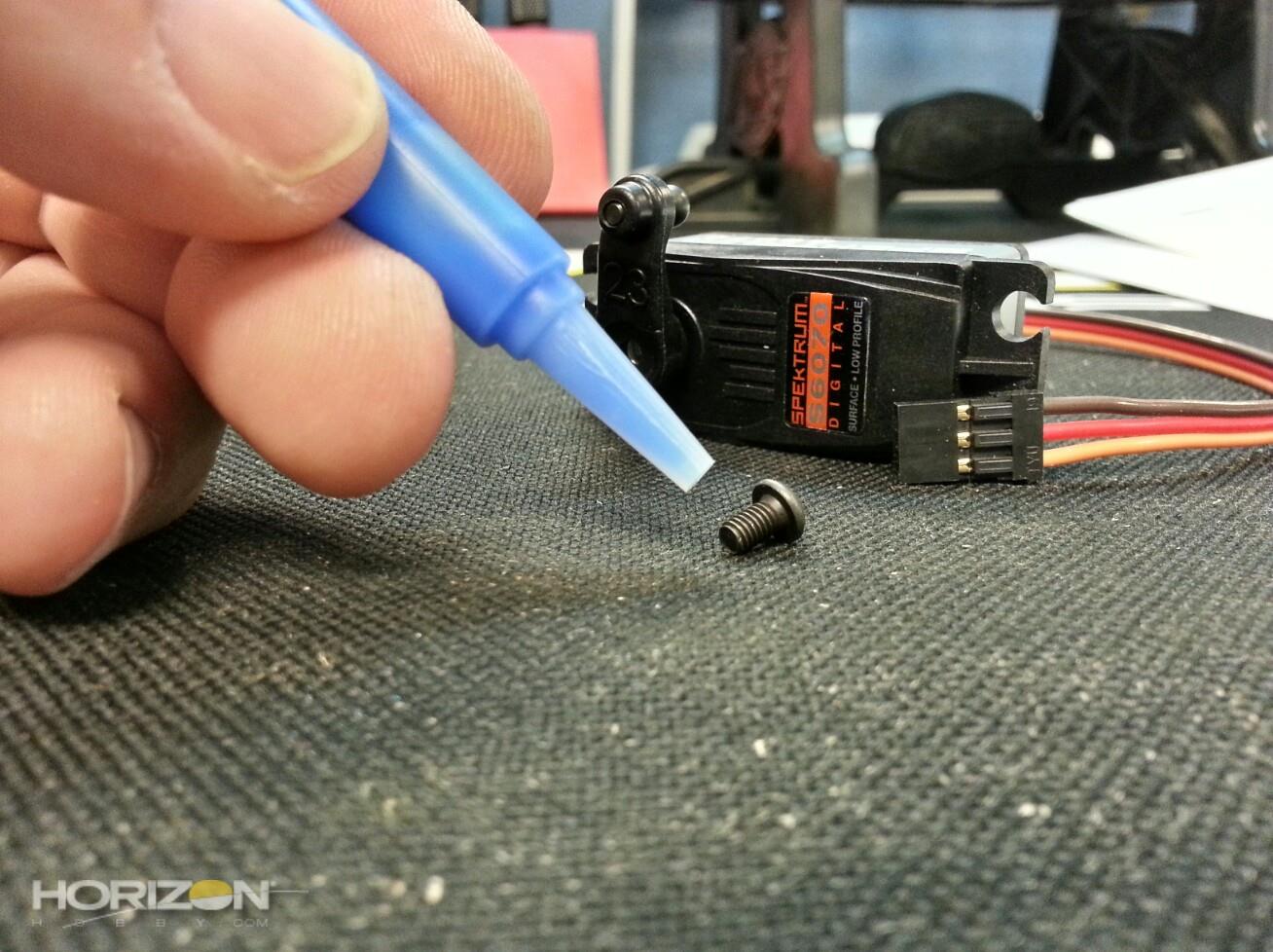
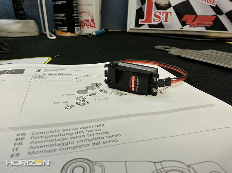
The servo arm installed.
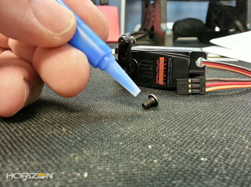
I do use just the slightest amount of TLR-LOK on the screw in the servo arm.
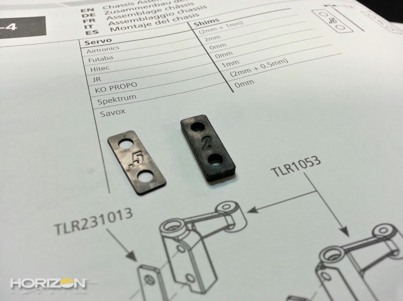
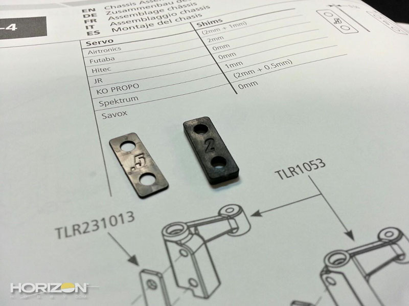
Make sure you get the right spacing for your servo by checking out the diagram in step A-4.
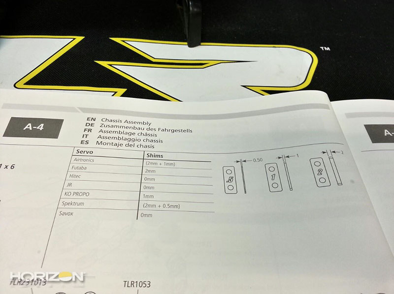
For our particular servo, the Spektrum S6070, I needed to use a .5mm and a 2mm shim on each side of the servo.
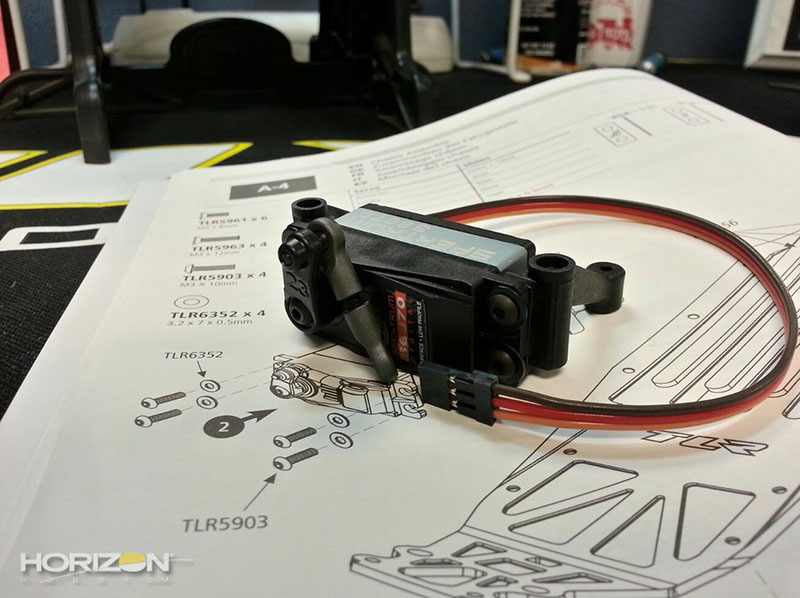
The servo with the servo mounts installed.
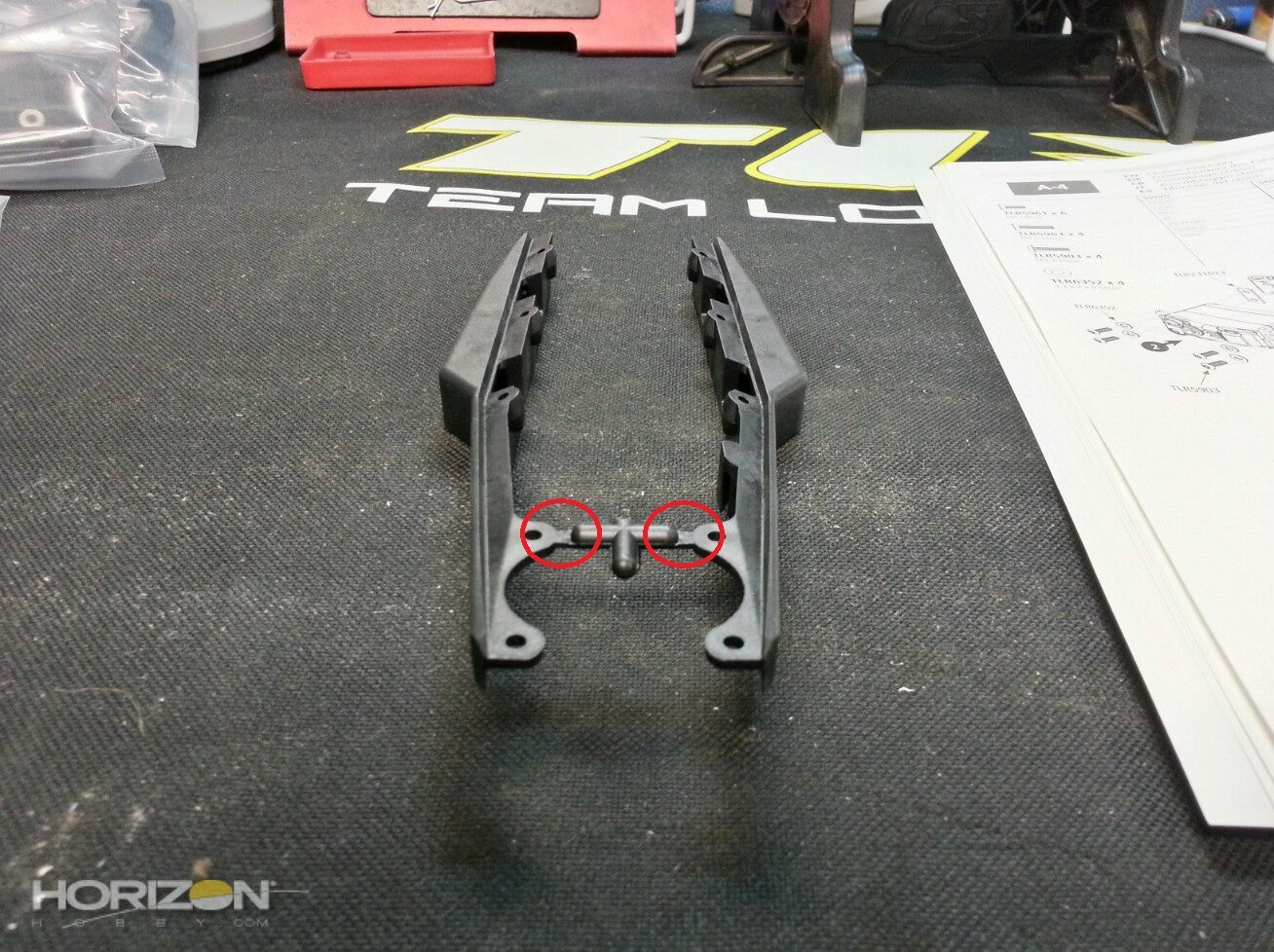
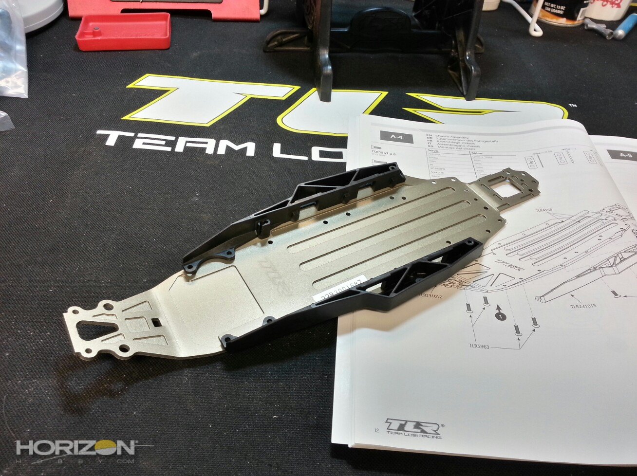
The chassis side guards. They are molded together and you'll need to remove some flashing before mounting them to the chassis.

If there's some flashing left over make sure you trim or sand that off.
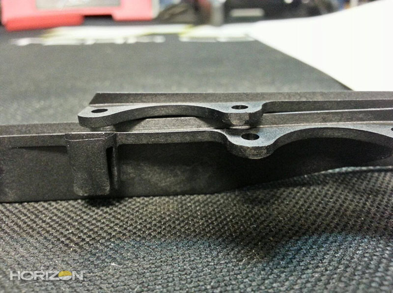
Here's our side guards, now ready for installation.
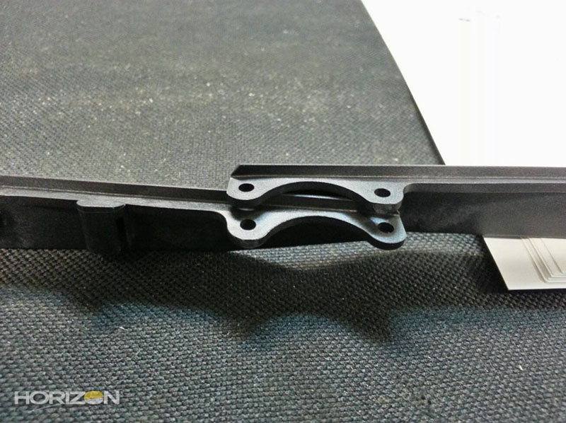
Side guards installed. I used the rear screws to mount them to the chassis first. This way they are held in-place while I mount the servo mounts to the chassis.
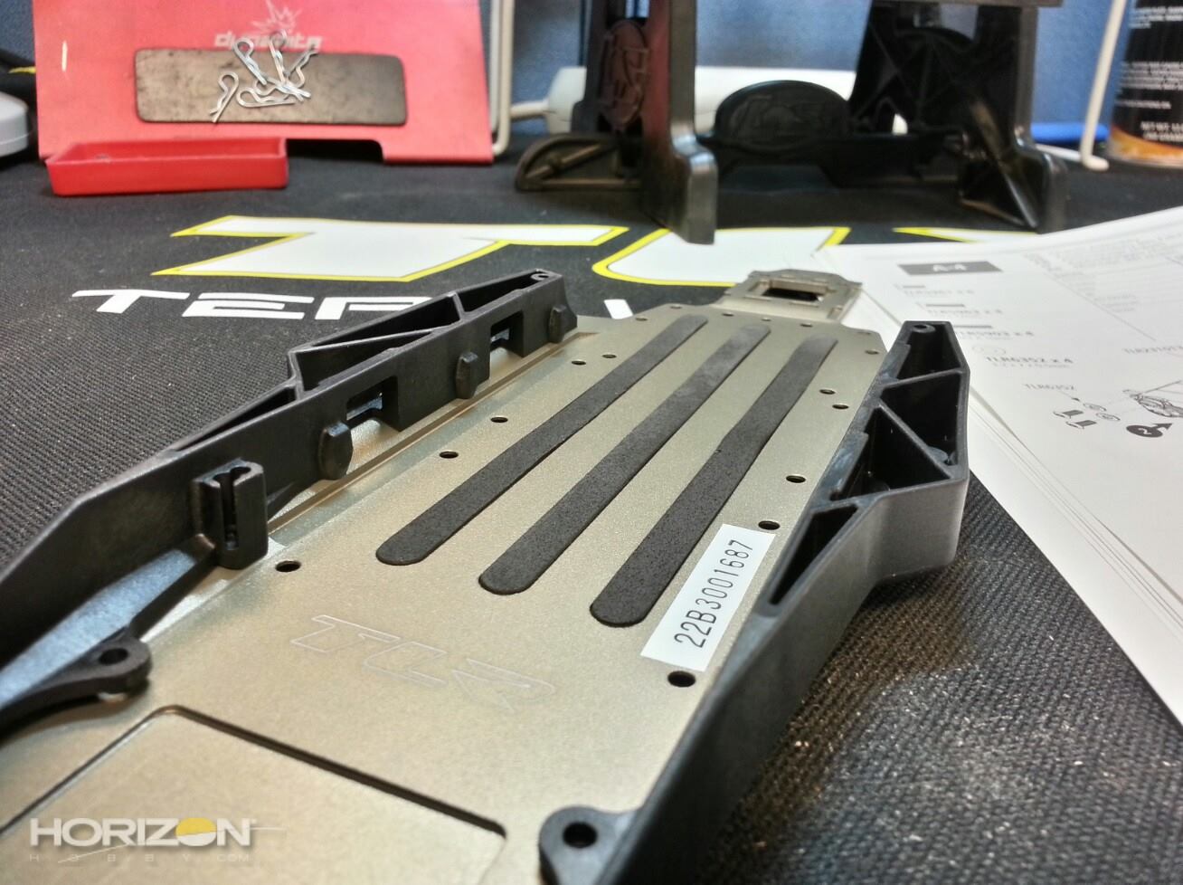
I seem to remember adding the foam strips towards the end of the assembly process on the original 22 however you add them early on now. These seem to fit in the channels better than the original as I had to trim my originals as they were slightly long.

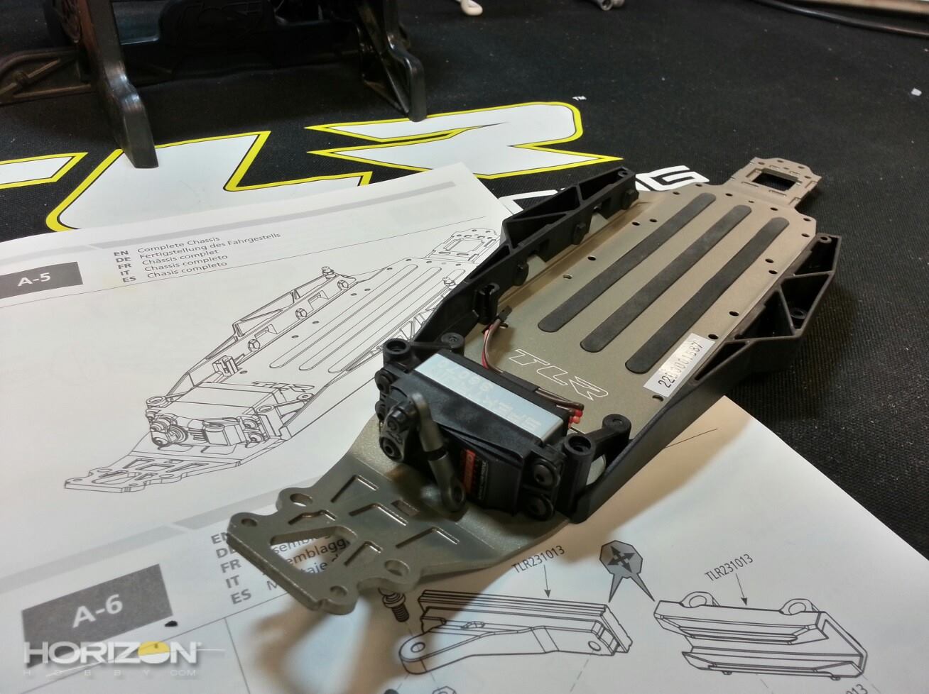
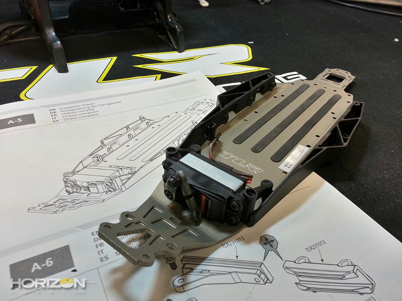
The servo mounted and in-place. I used a small piece of heat shrink tubing to keep the servo lead together.

A front-look at the servo installed on the chassis.
Team Losi Racing includes these super-trick looking aluminum body mounts. I, however, will not be using these as I'll be using hook-and-loop fasteners to keep the body on. I have used this process in the past and it works very well.
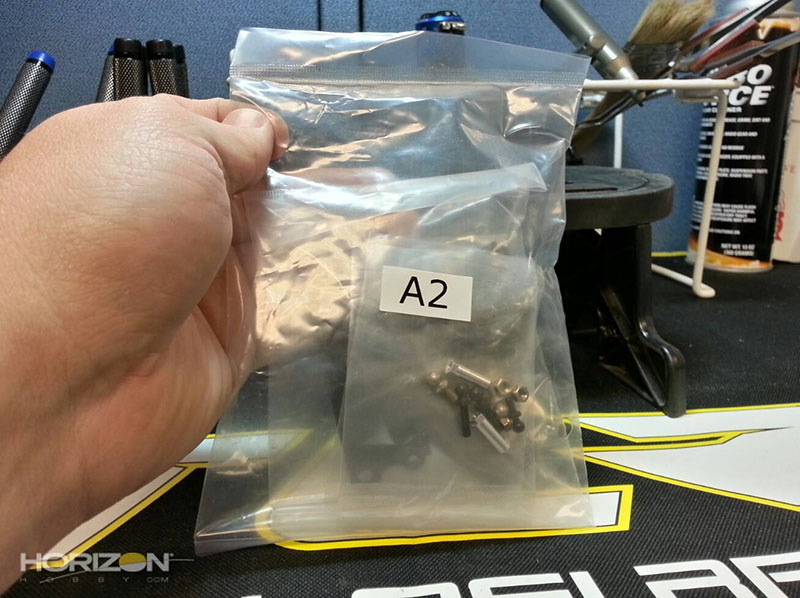
On to bag A2, the slider rack.
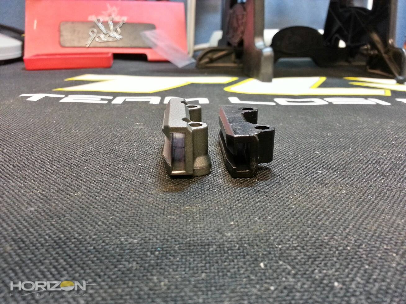
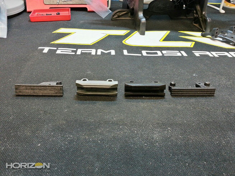
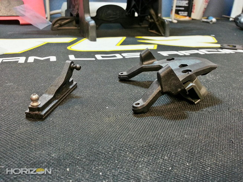
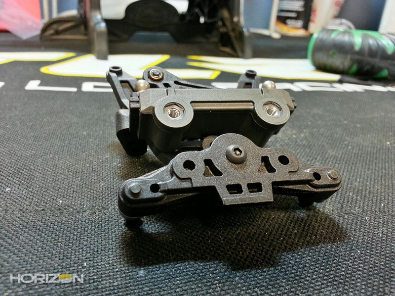
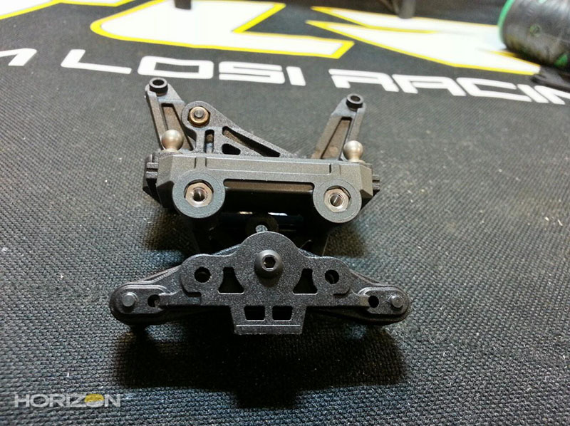
Here you can see the differences made to the slider rack. The original slider is on the right, the new one on the left. The new rack has much more surface area than the original for better load bearing and reduced slop.
You can almost fit the groove of the old rack into the groove of the new rack. This have been beefed up quite a bit!
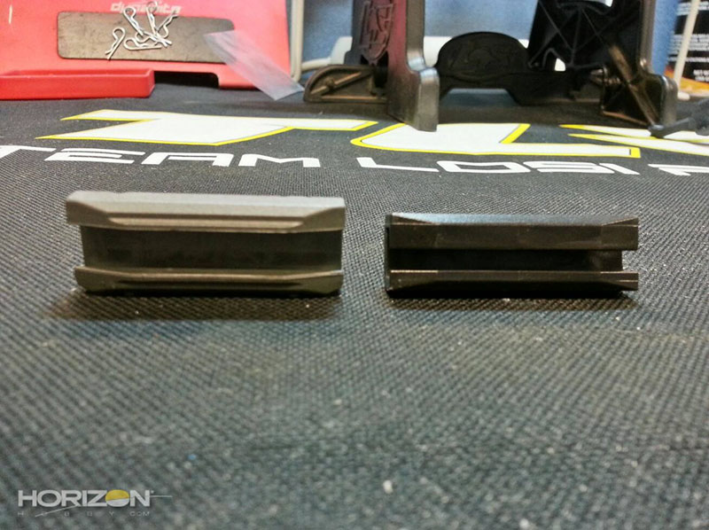

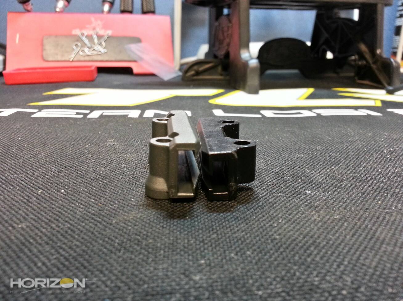
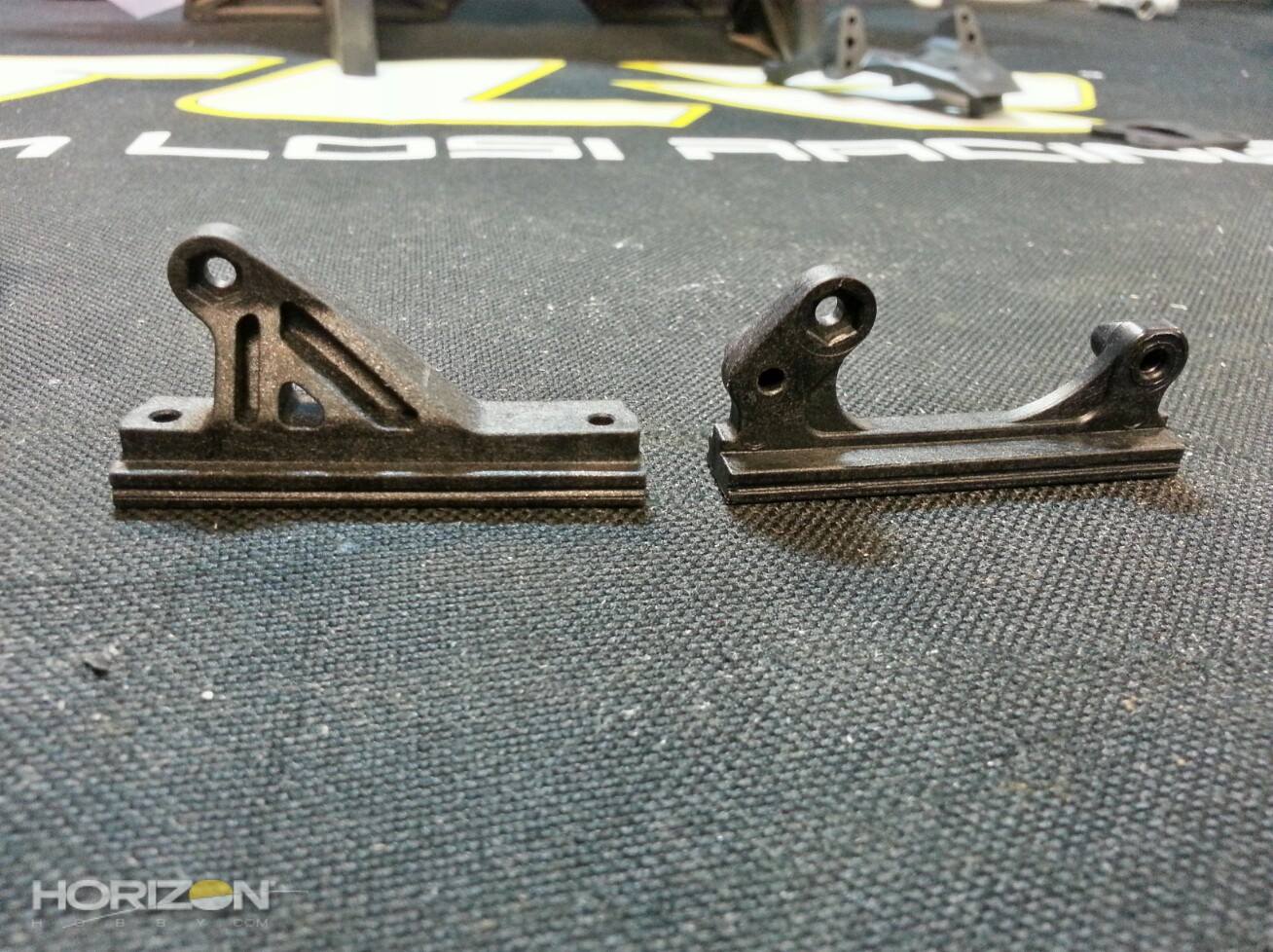
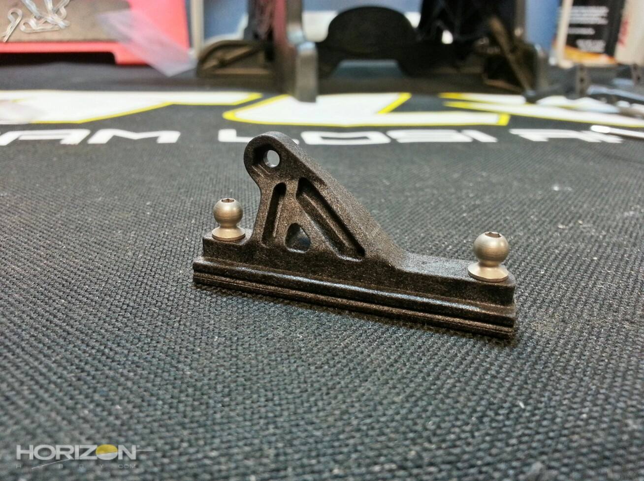
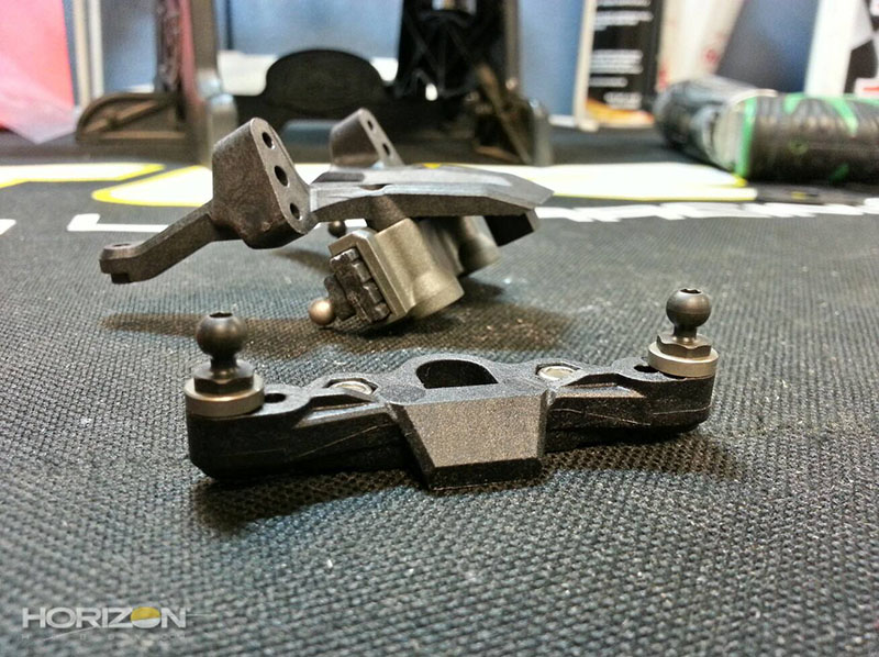
The tongue portion of the slider rack, original on the right and new on the left. Again this has been beefed up in a lot of different places. Additionally the ball stud position has been moved from a vertical to horizontal position.

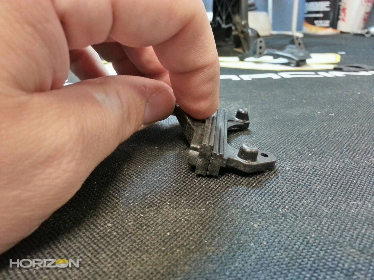
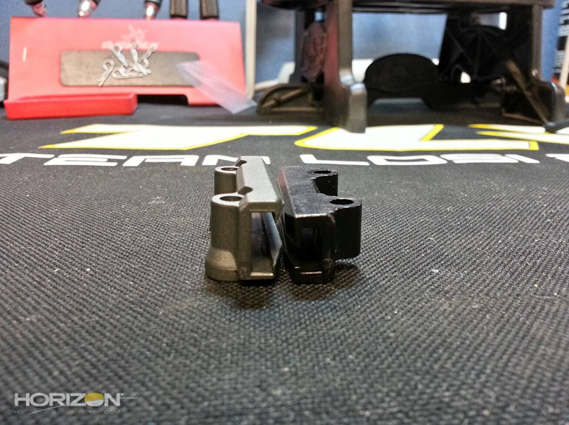
Here you can see the difference in the thickness of the tongue-portion between the original and the new rack.

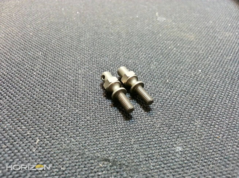
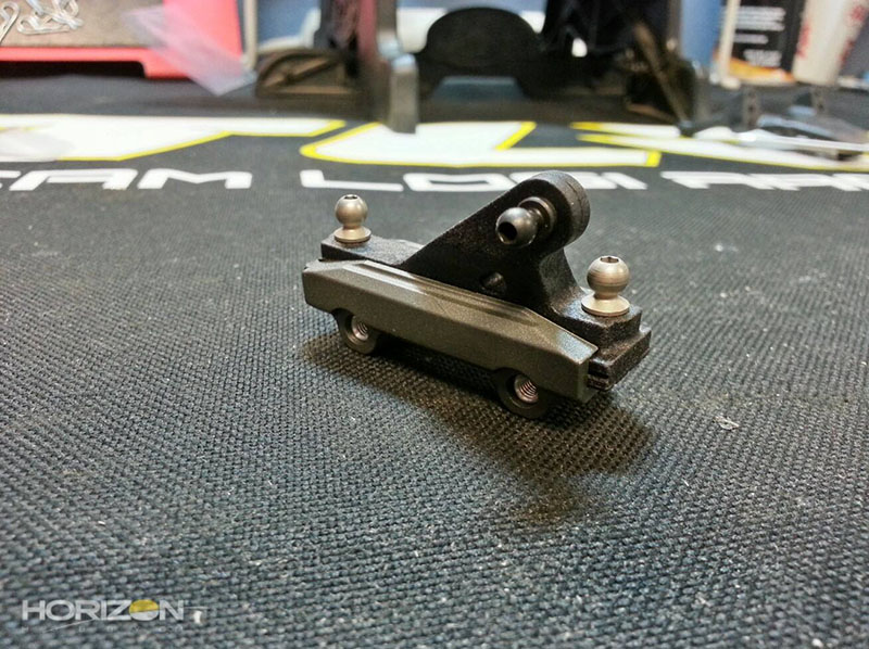
The horizontal ball studs installed.

The ball stud for the steering link in-place.

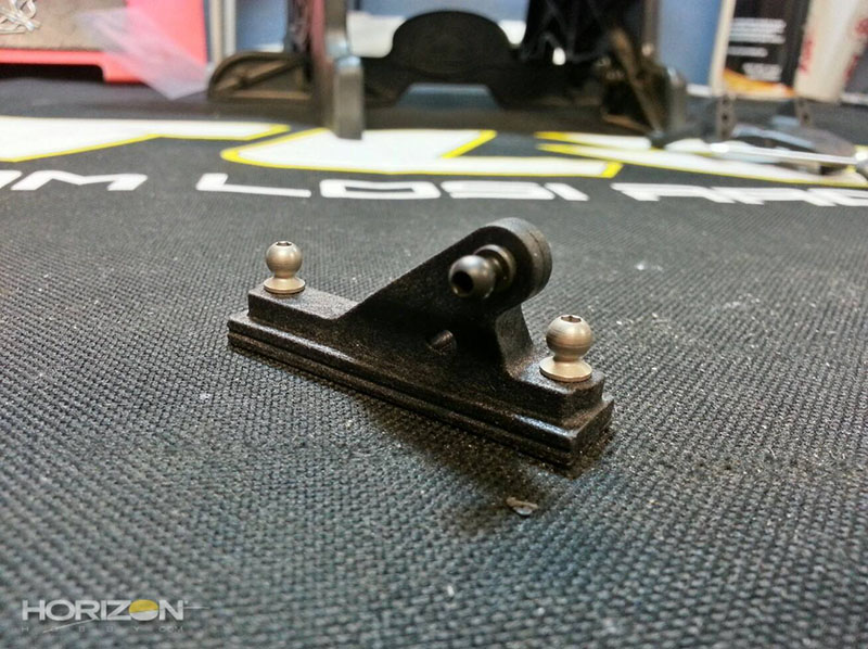
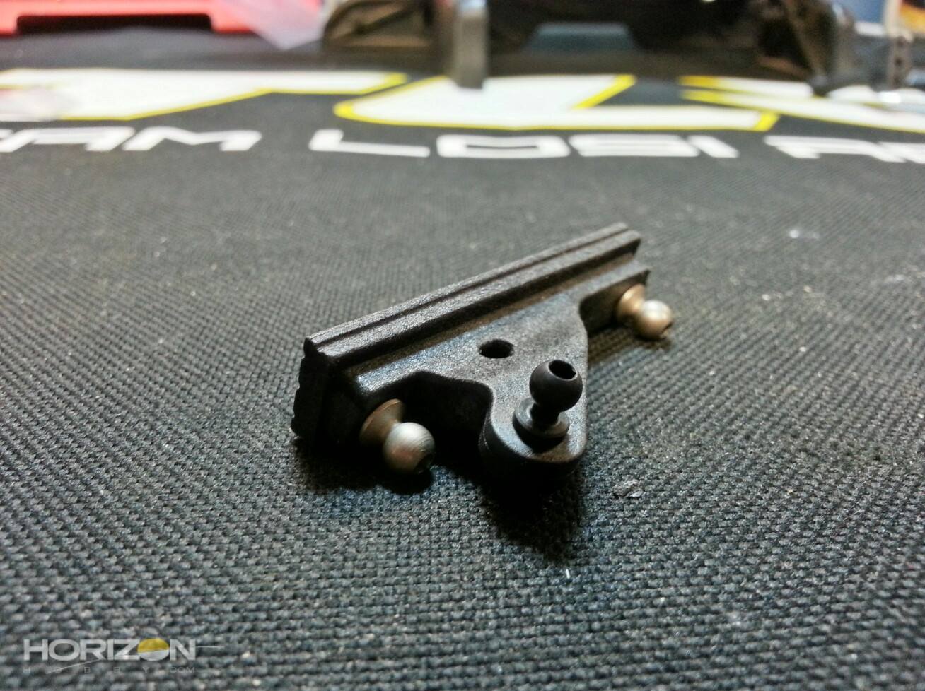
The slider rack ready for installation in the front clip.
To make it easier to bolt everything together I slid the slider out of the rack, then bolted this together.
The steering rack fully installed.

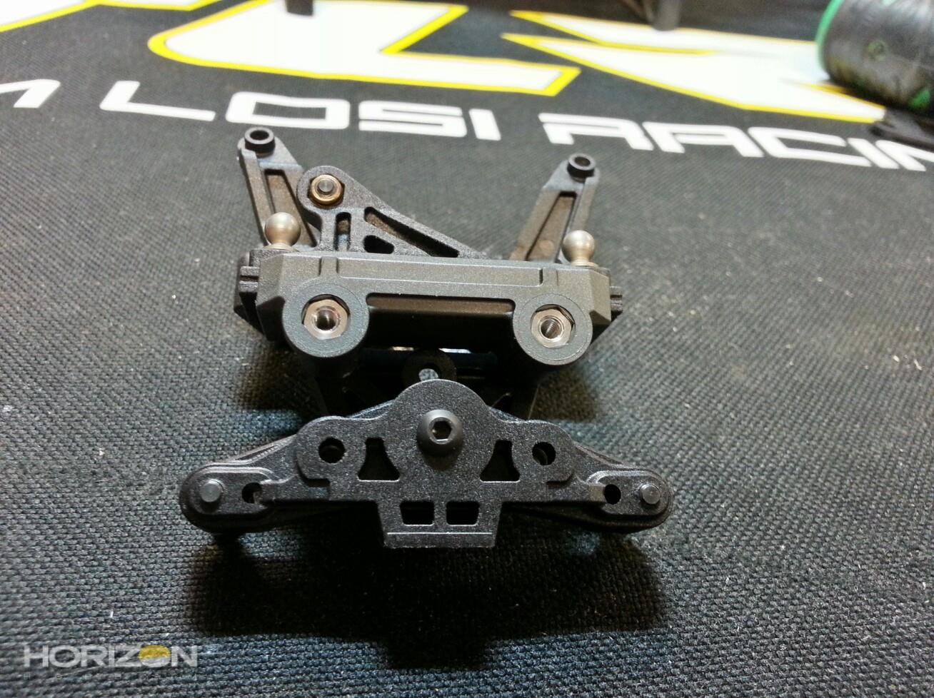
The front camber block. Do not forget to install the 2 lock nuts as, if you do, you'll have to remove this from the upper bulkhead later on.
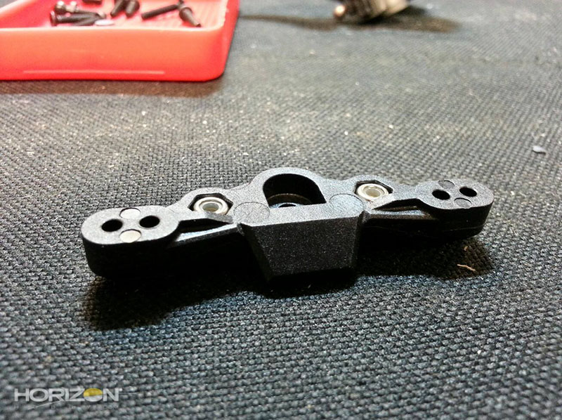
The front ball studs installed. Note the aluminum roll center shims that are included as standard equipment! Pretty trick!
The front camber block attached to the front bulkhead. I do not tighten this screw down all the way as I'll need to be able to align these screw holes with the screws that come up through the chassis later on.
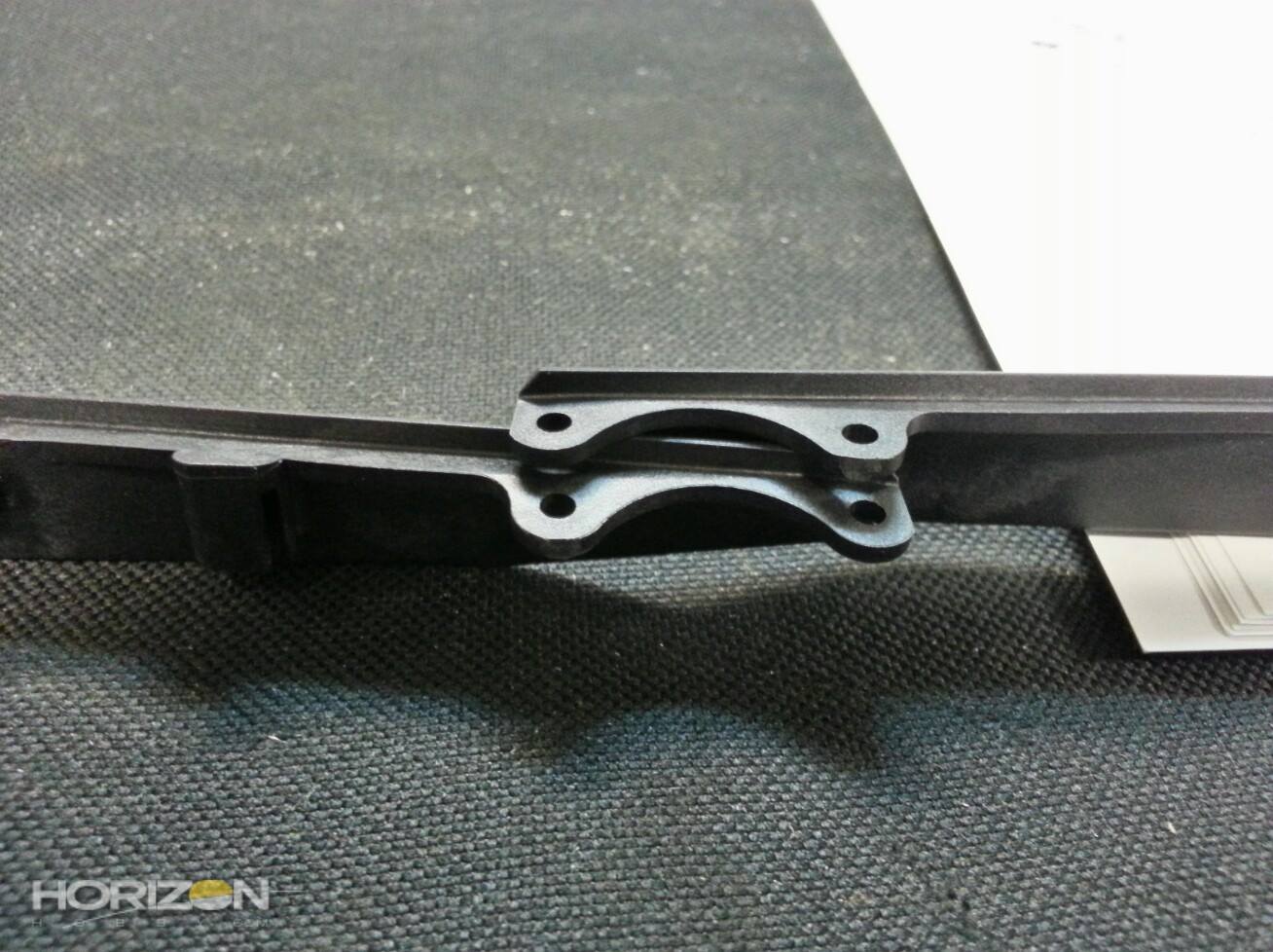
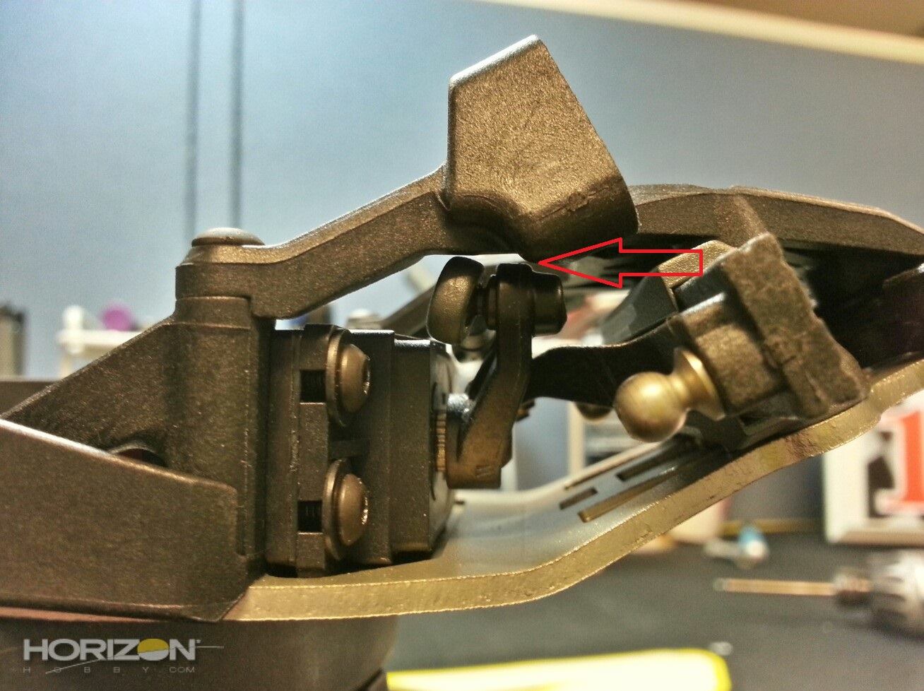
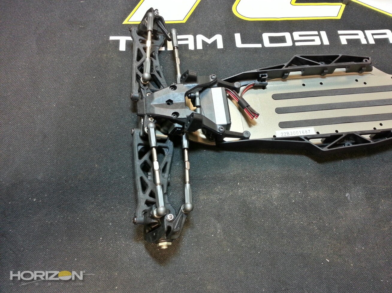
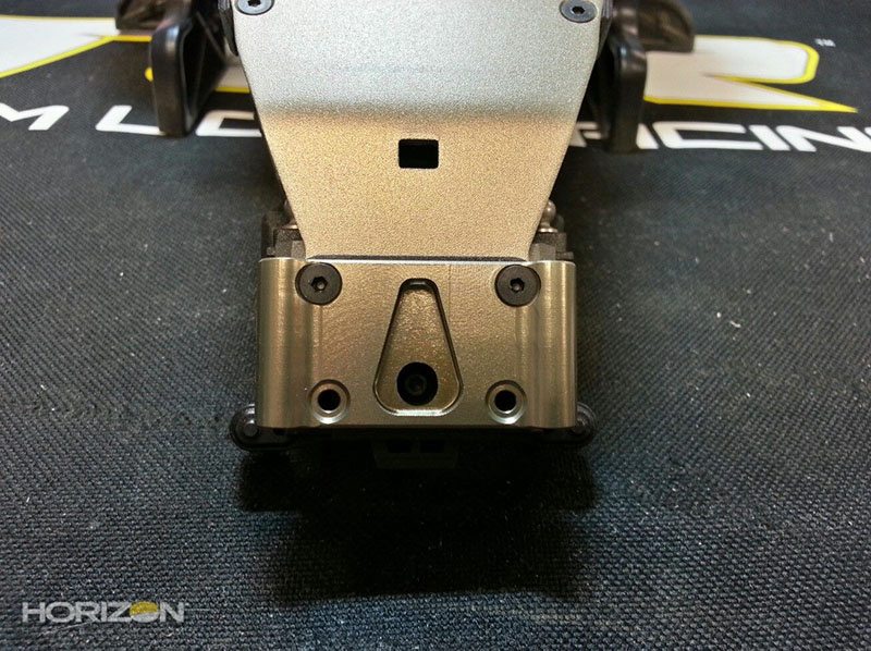
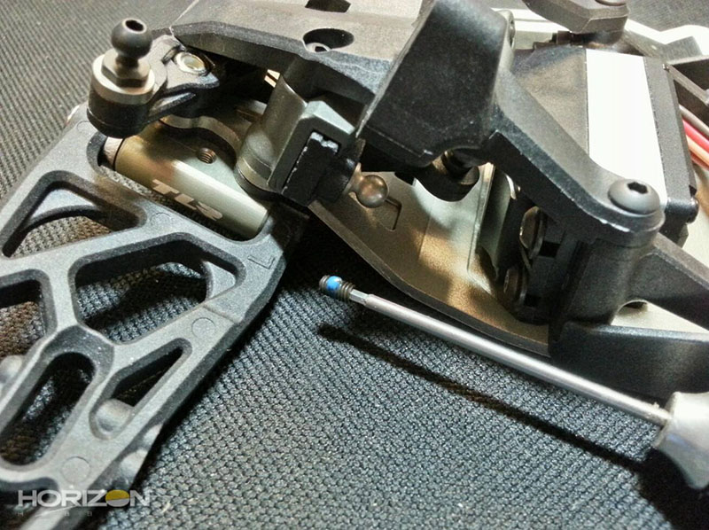
The front bulkhead and slider on the chassis. Note the gap pointed out by the arrow. You need to have this spacing to make sure the servo arm doesn't hit the upper bulkhead and obstruct the full range of motion.

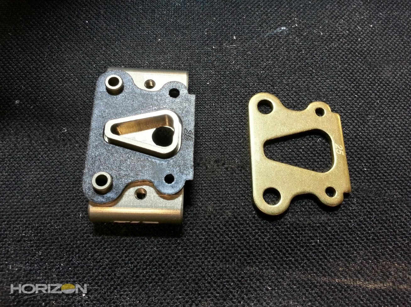
The 22 2.0 includes a 25° front kick shim. Team Losi Racing does offer an optional 25° kick shim out of brass (TLR1049) for additional weight over the nose that you can use as a tuning option.

The front kick shim and kick plate installed.
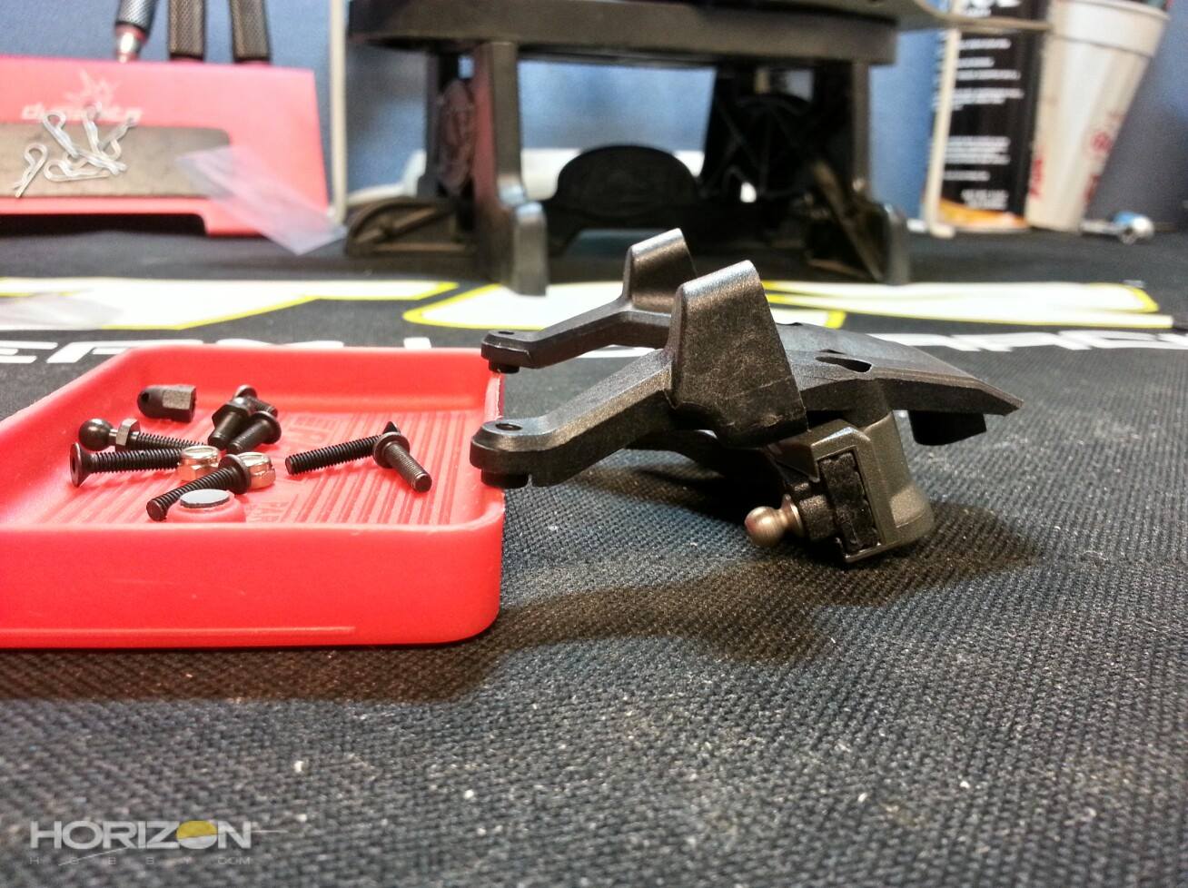
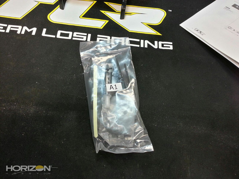
On to bag A3, the front suspension parts!
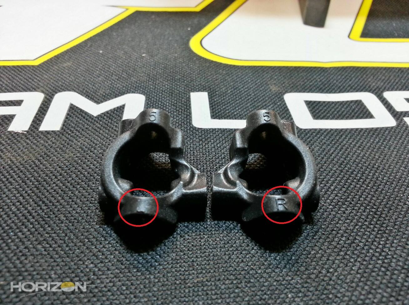
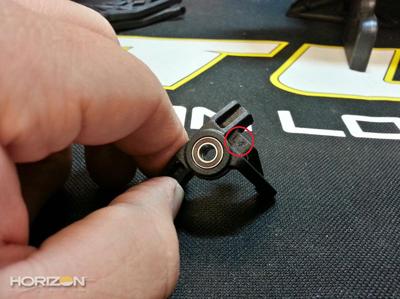
The 22 2.0 includes redesigned front spindles. They are labeled left and right to help make sure you install the correct spindle on the correct side of the car,
I use a touch of TLR-LOK on the screw that holds the front axle in-place.

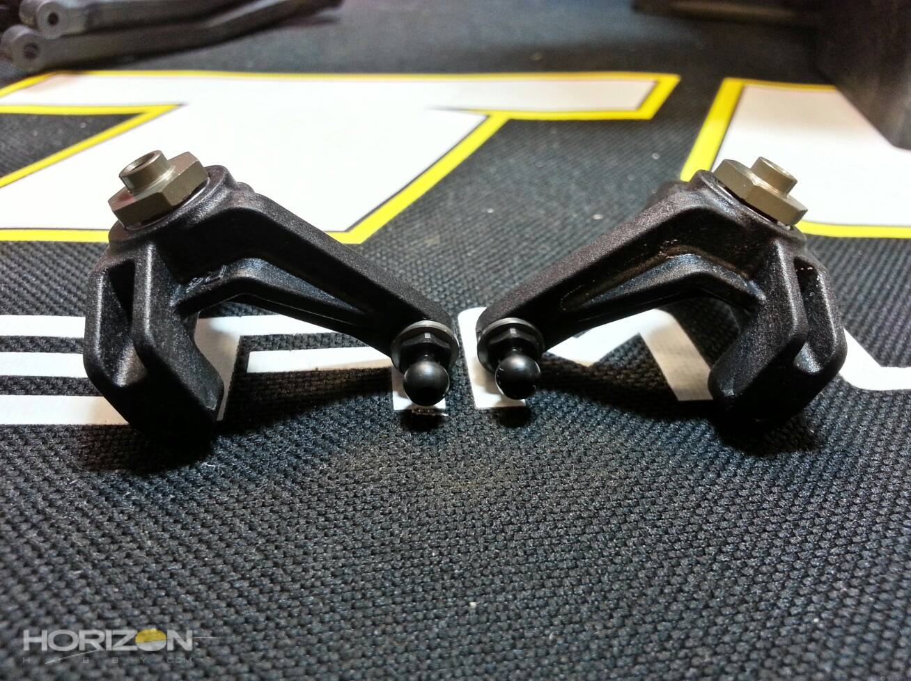
The front spindles with the axles and steering ball studs installed.

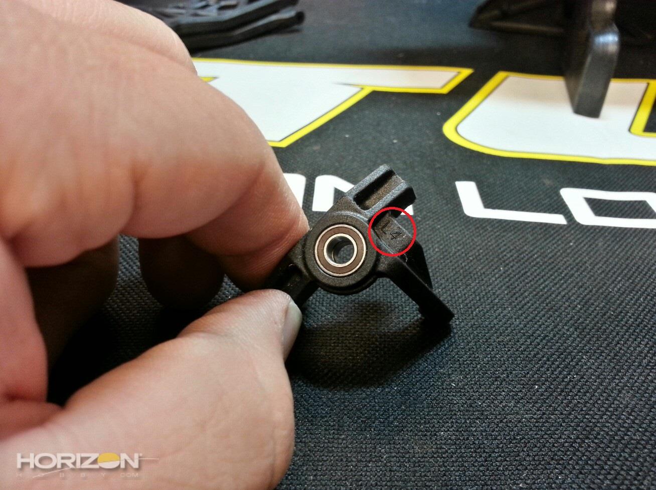
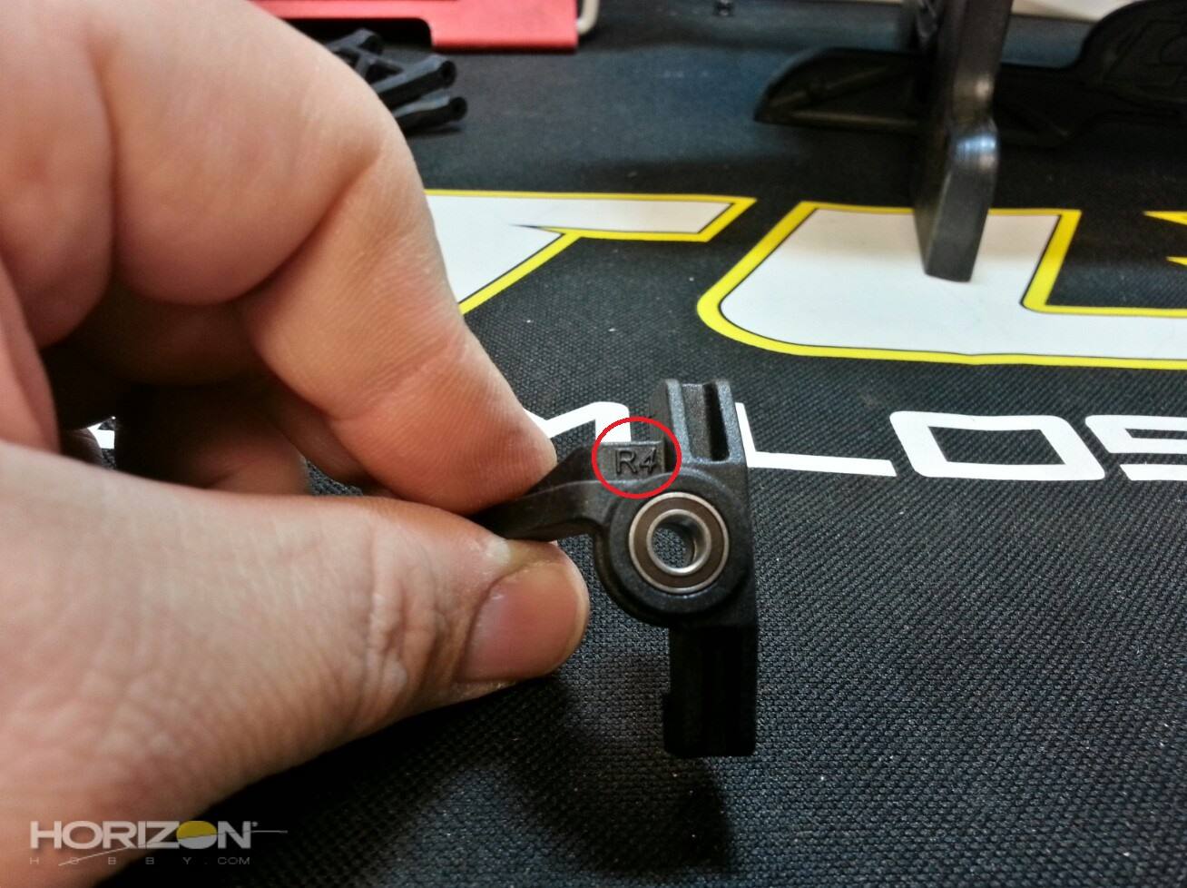
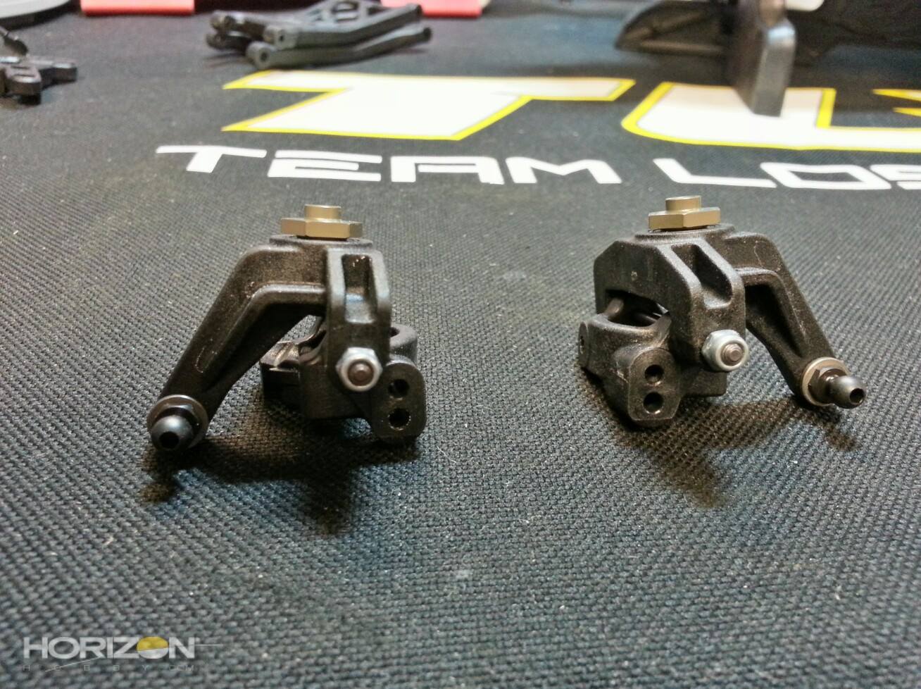
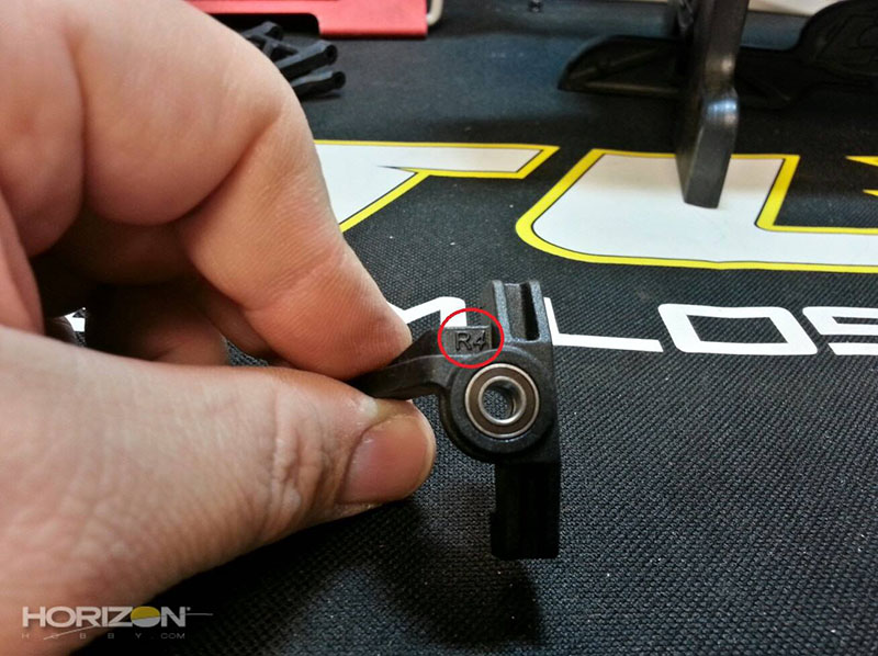
The front caster blocks, much like the spindles, are labeled L and R to help get the right amount of caster in the car. The kit spindles feature 5° of caster molded into them. When combined with the 25° front kick plate you have 30° of front caster.

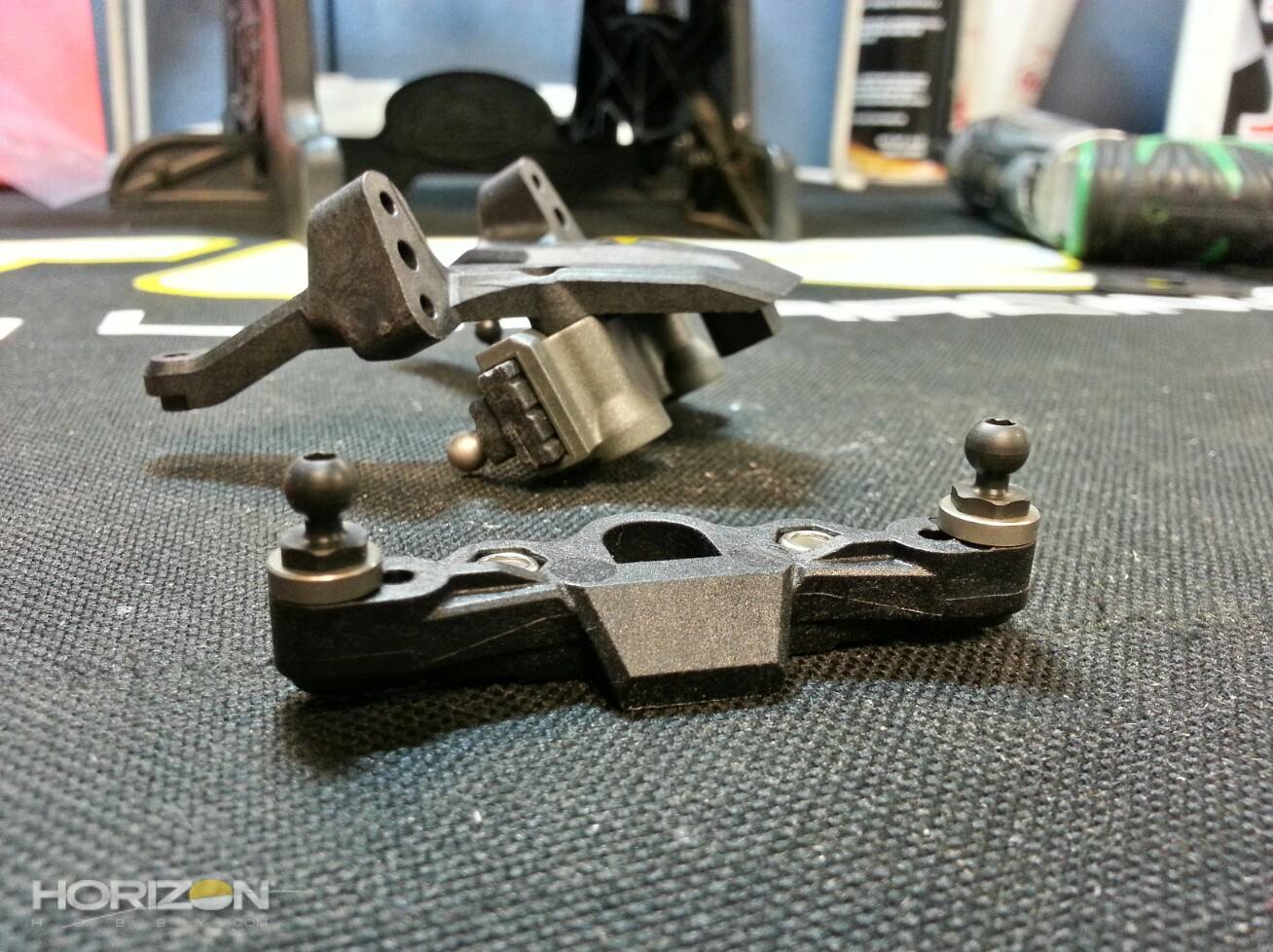
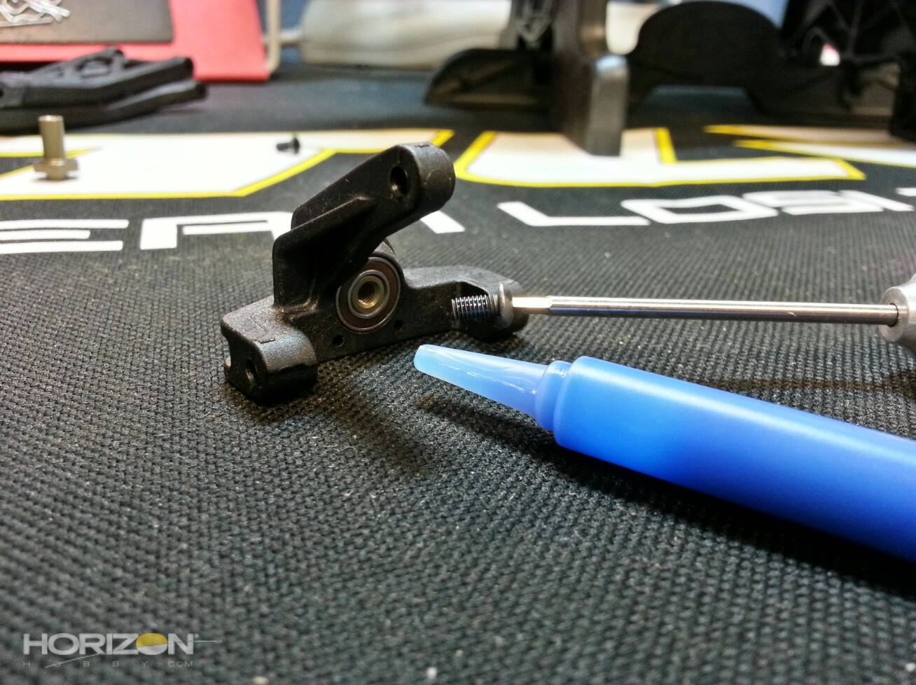
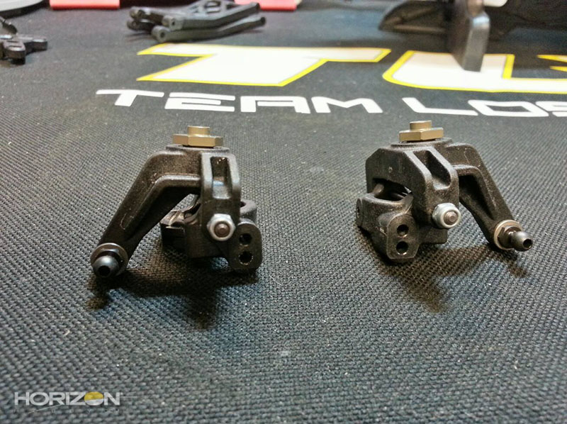
The front spindles and caster blocks. All that's needed is the outboard ball stud for the camber links and these are ready to go. The front king pins feature Ti-CarboNitride coating for a super-smooth result.
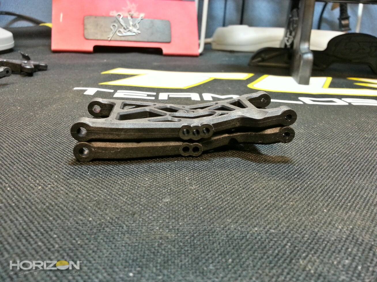
The 22 front arm (top) compared to the 22 2.0 (bottom)


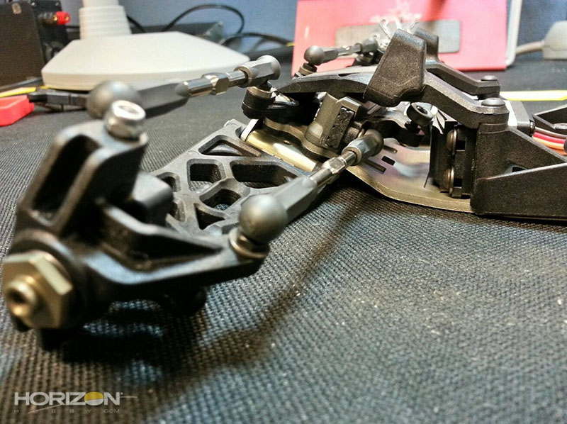
The front caster blocks and steering blocks installed.
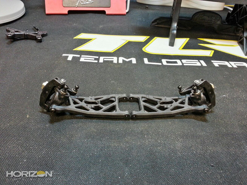
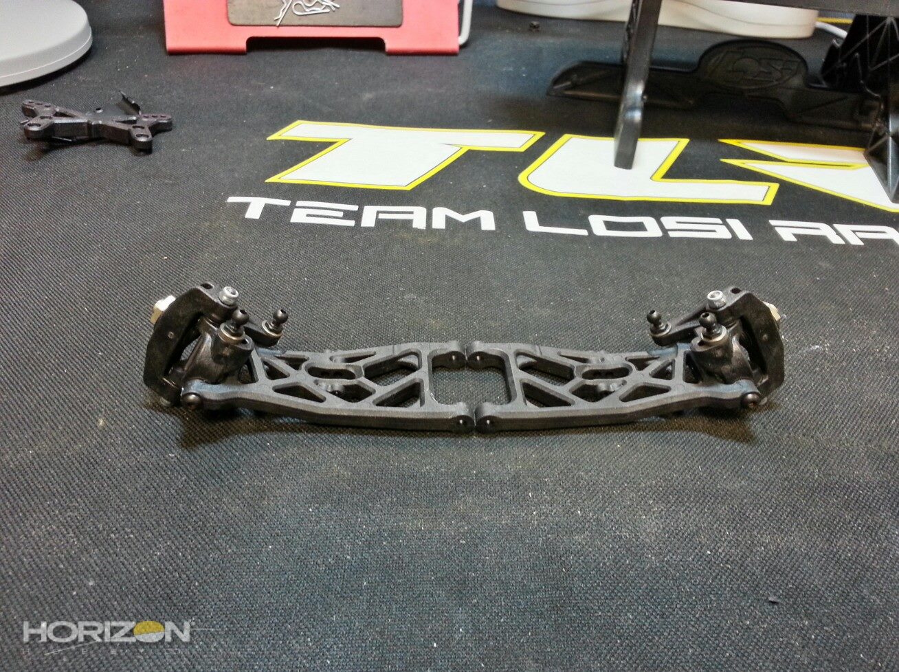
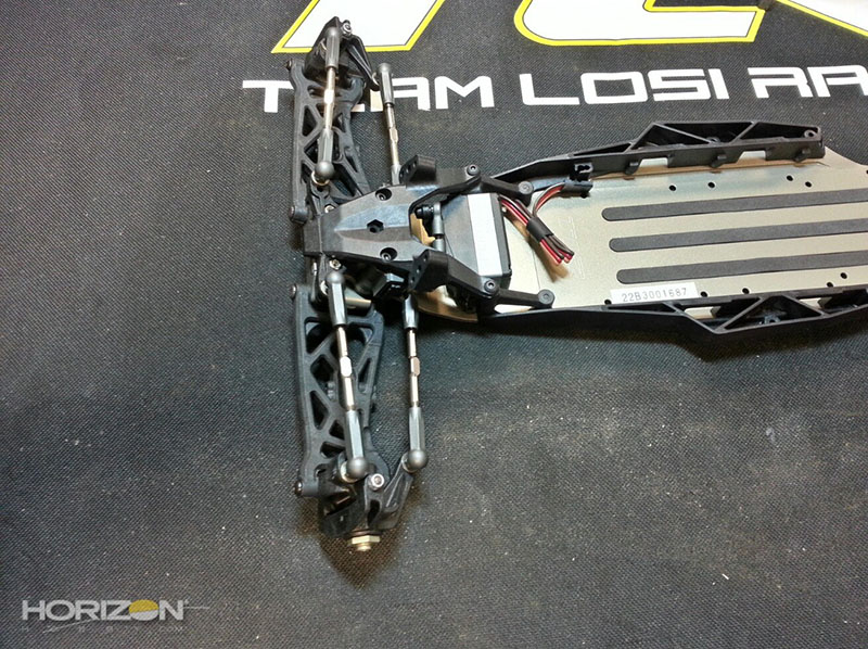
The front A-arms attached to the front kick plate. Much like the front king pins the inboard hinge pins feature the Ti-CarboNitride coating. The result is a very free range-of-motion.
Use a drop of TLR-LOK on the set screws that hold the front hings pins in-place on the front kick plate.
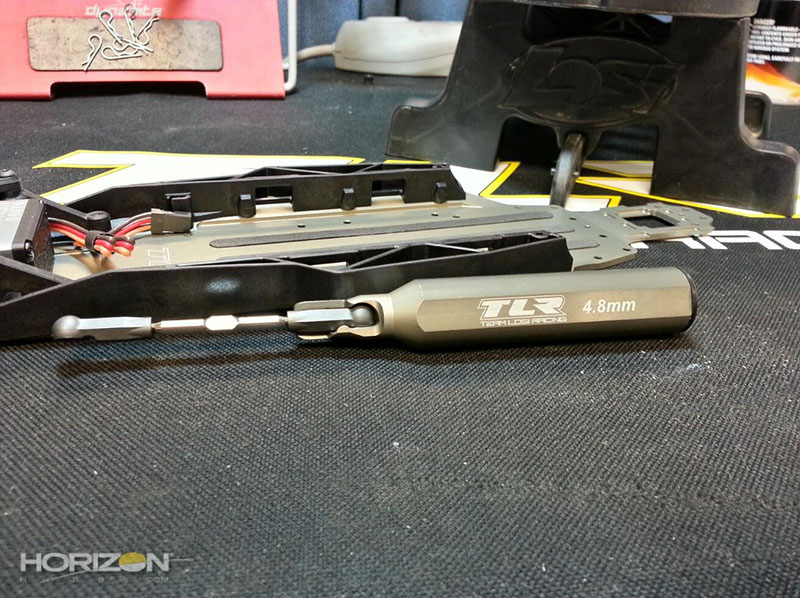
This is one of the best purchases I have ever made in the TLR Ball cup wrench (TLR72000). This, when combined with my turnbuckle wrench, makes it really easy to thread ball cups onto the turnbuckles. I, again, used a little bit of black grease on the threads to make threading them in a bit easier.
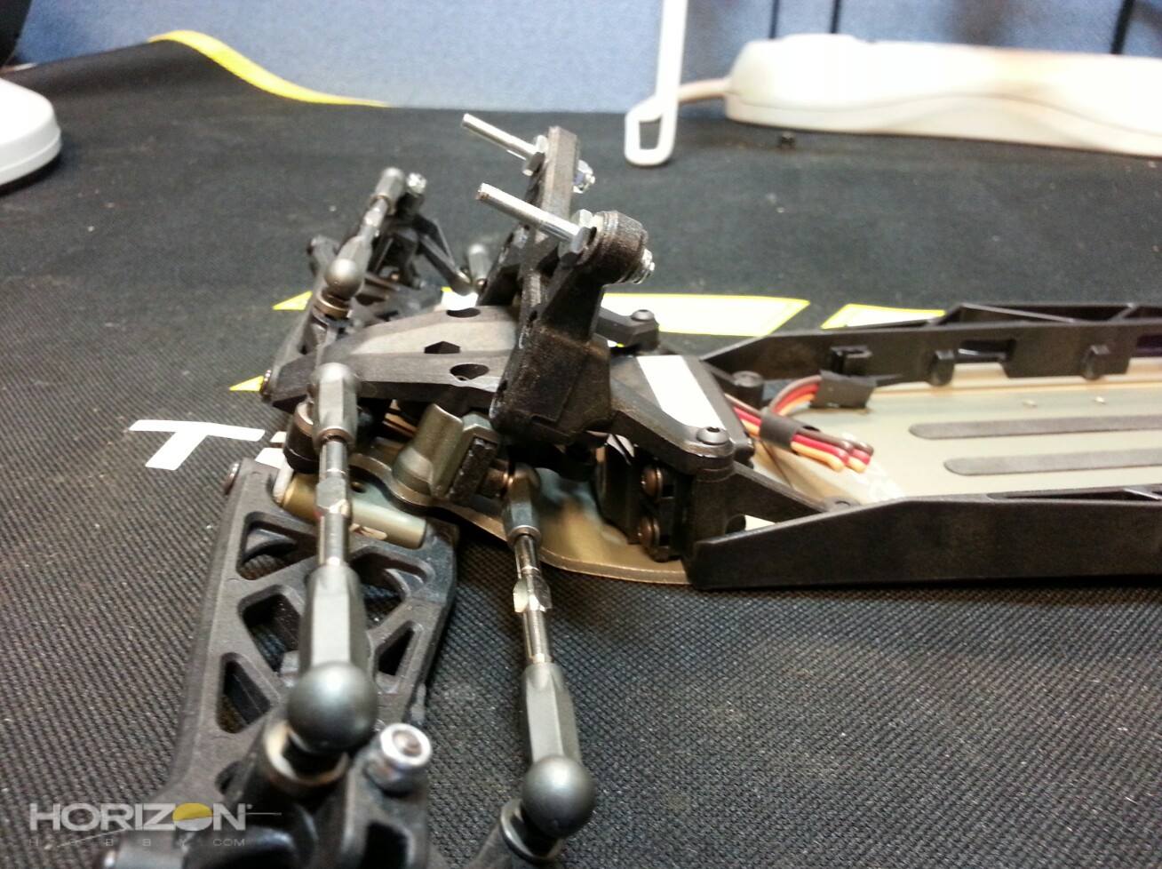
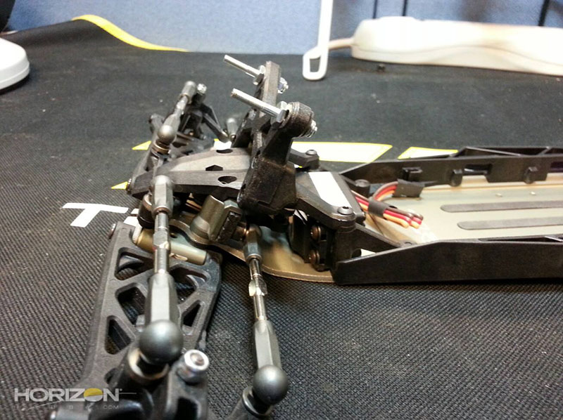
The front camber links installed. I used a digital caliper to get them to an equal length of 78.9mm on each side.
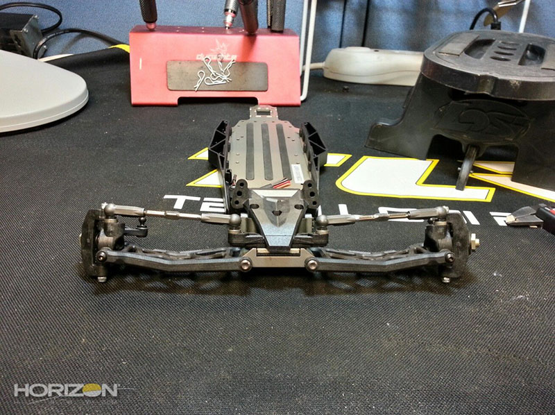
The steering links installed. I also measured these out with my digital caliper to a length of 78.8mm.
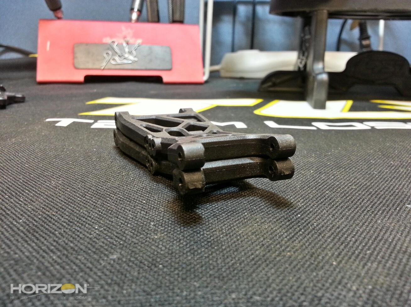
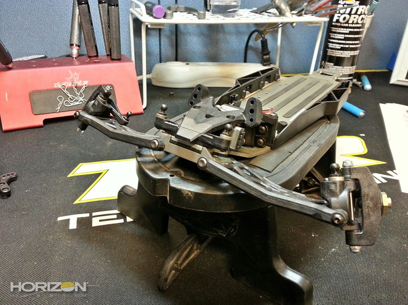
Those are some long A-arms and links!
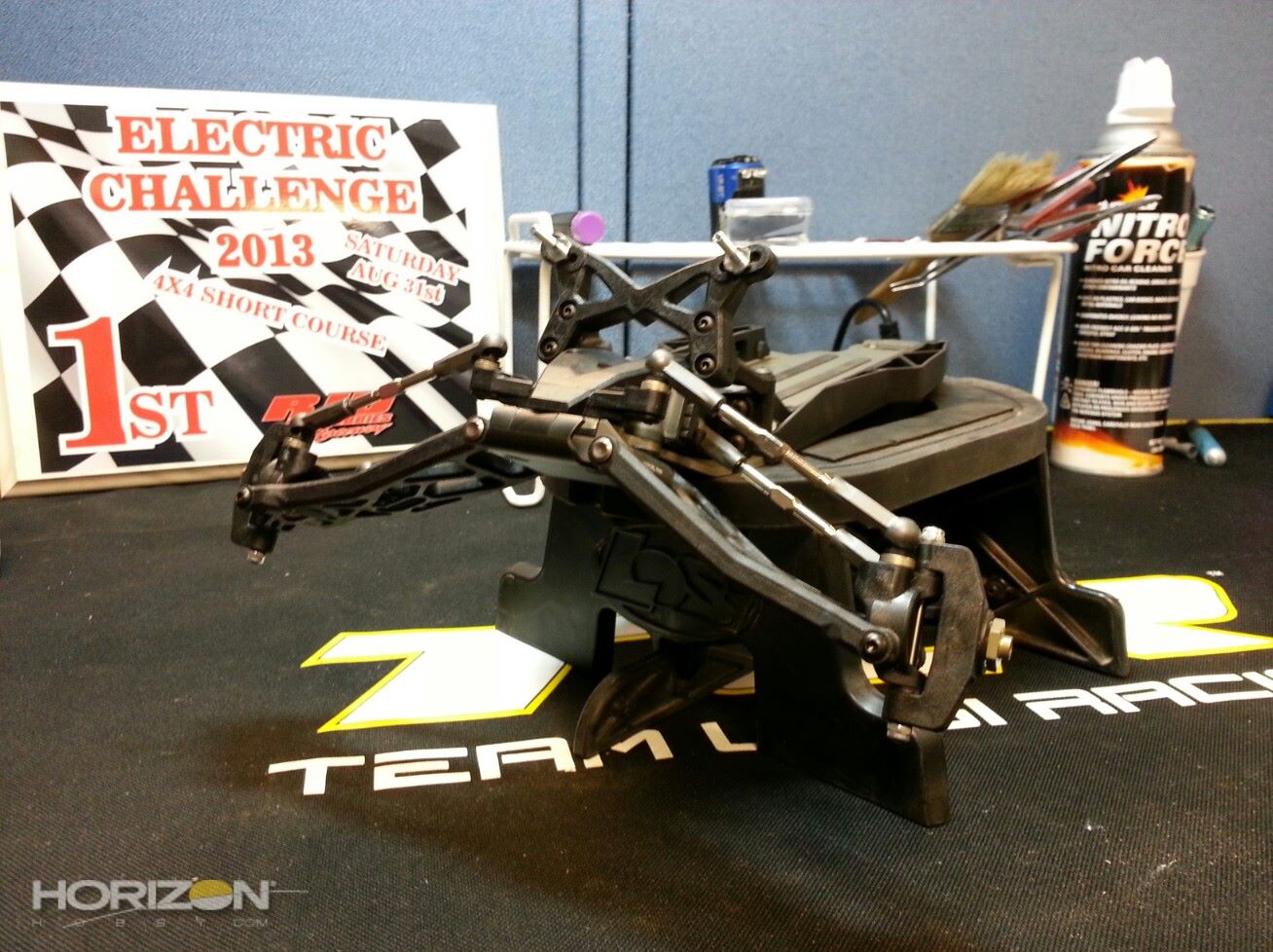
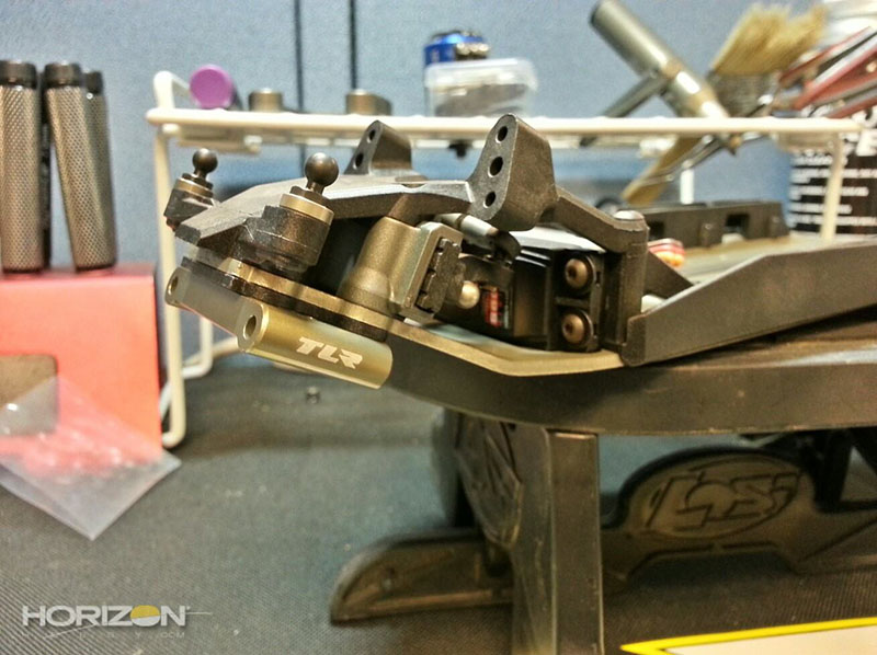
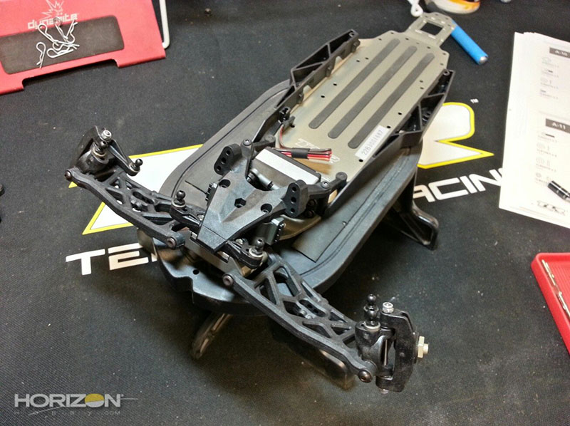
The front shock tower and upper shock mounts installed. There is a right and wrong way to install the upper mounts.
The front end complete, on to Bag B!

Previous - Page 2 - Next
Source:

|