|
- Team Xray XB4 - JE Models - Build -
Over the course of this page we will be building the Team Xray XB4 1/10 4WD Buggy Kit and photographing all stages of the build. We will provide high quality photos and descriptions of all the steps in building this great new buggy from Xray.

Opening the small box reveals all the components included in the kit
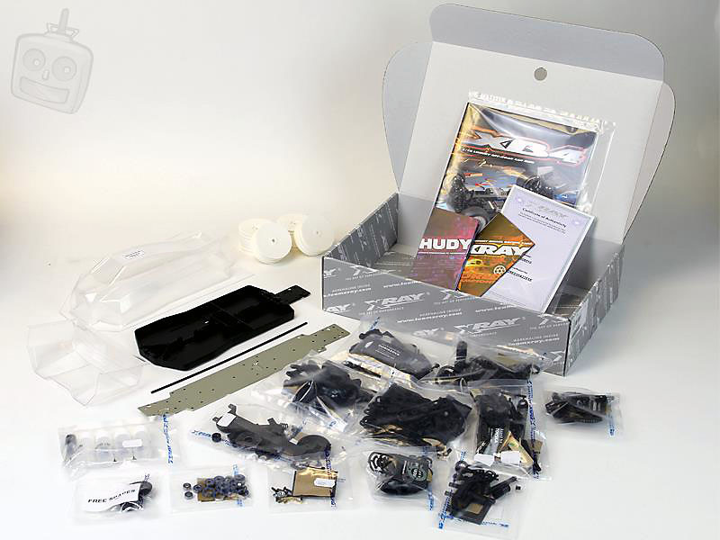
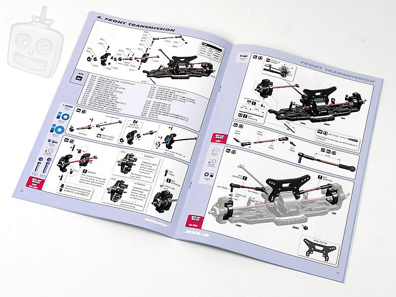
Xray include a full colour manual with detailed graphics and illustrations, it's the little things that help. Scale drawings of screws and fixings on the pages help you identify what screw might be needed, or bearing e.t.c.
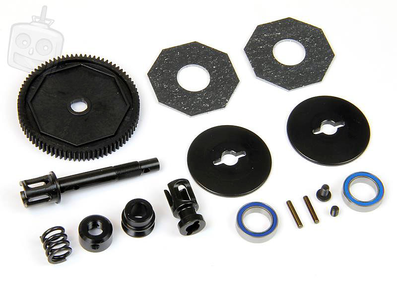
First up are the differentials. The XB4 uses sealed gear differentials that use a composite set of gears, controversial but they should be fine if used correctly.
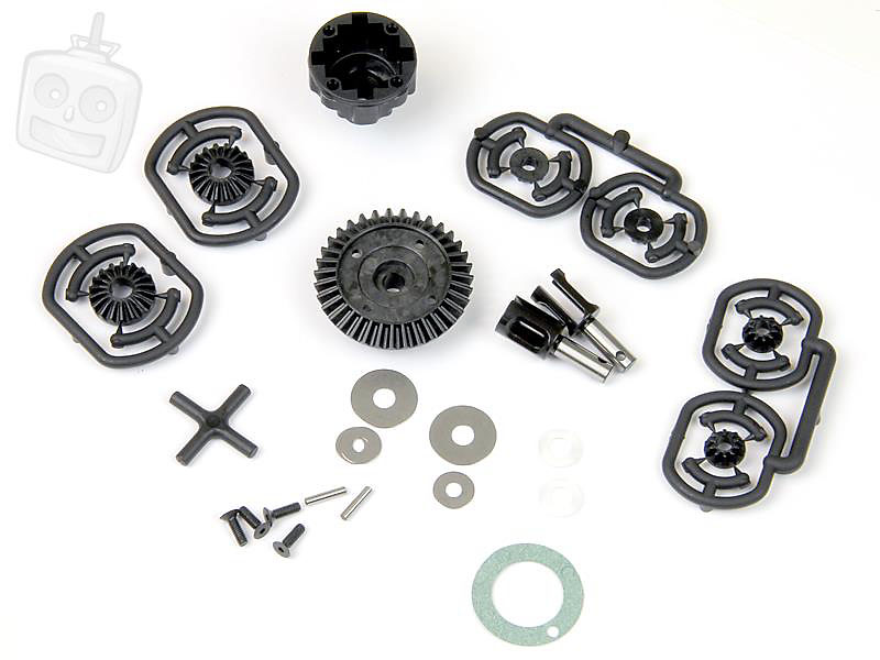
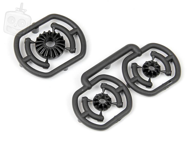
The composite gears are all injection moulded from 4 points to ensure an even distribution of the composite material. They feel very tough!
Here's one of the diffs topped up with silicone oil, Xray include a set of oils in the kit to give you a base setup. The small planet gears sit on a composite holder.
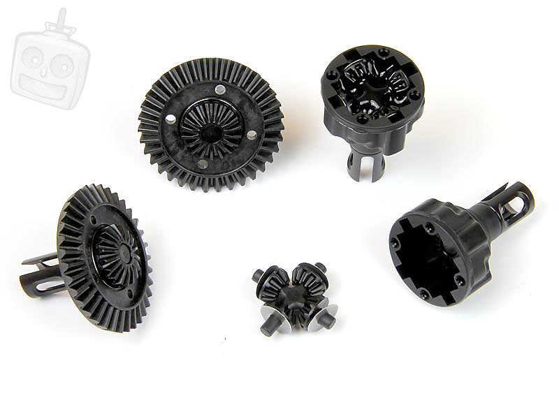
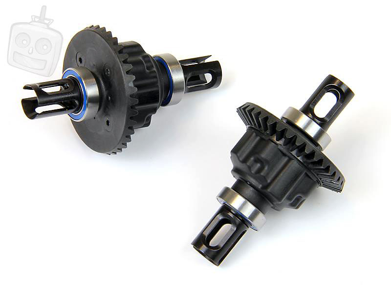
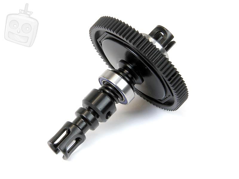
Two completed diffs! These diffs are very lightweight due to the use of composite gears, lightened steel outdrives are included as standard which is a nice touch.
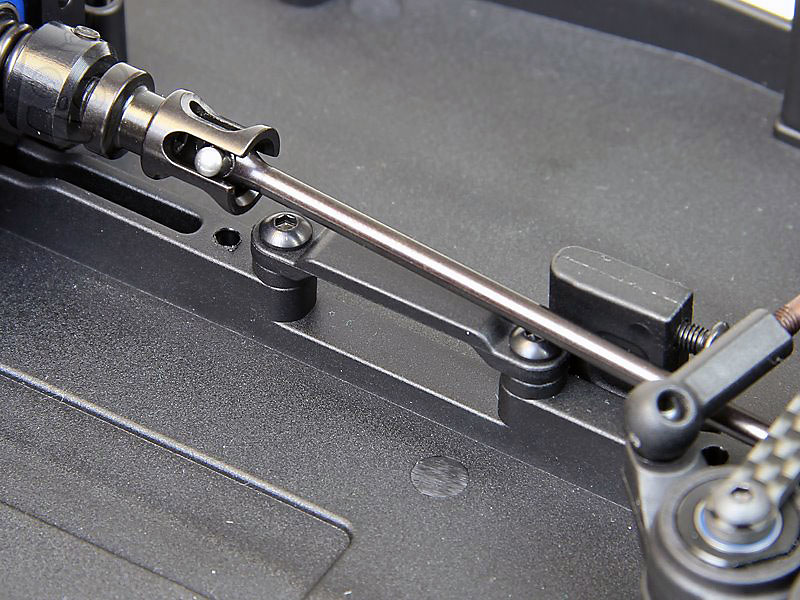
Here are the front and rear center driveshafts. As with most modern models the old grub screw retaining system has been ditched and the pin is now captured with a composite ring that slides over the joint.
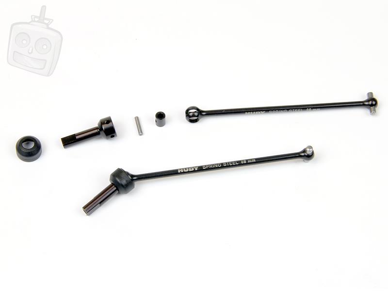
The driveshaft connects up to the composite pinion gear through the gearbox and a screw ensures the gear stays attached to the driveshaft.
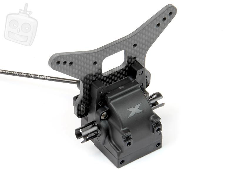
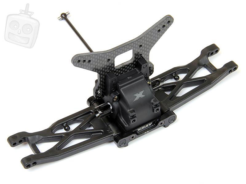
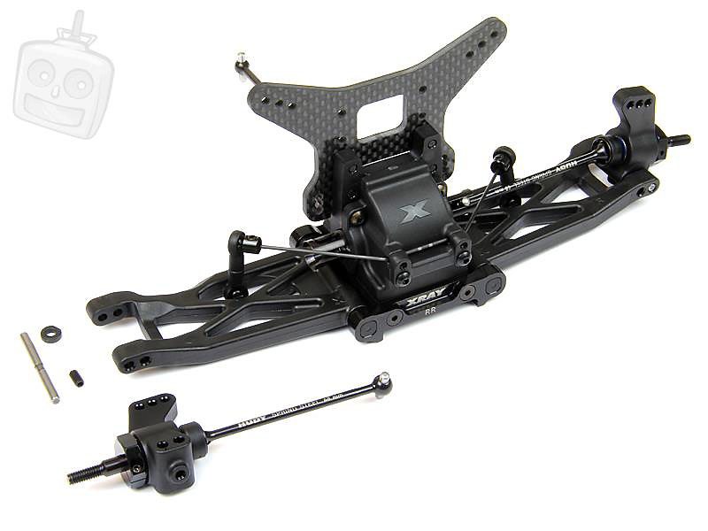
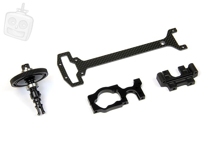
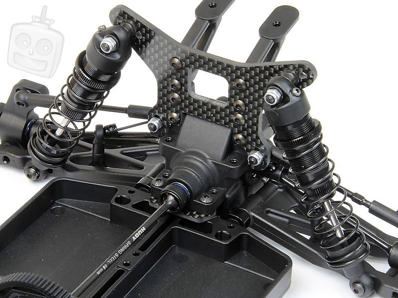
Here's the assembled rear gearbox with 3.0mm carbon fibre shock tower attached.
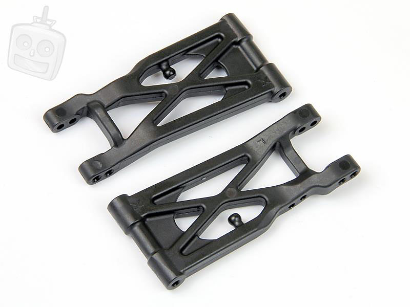
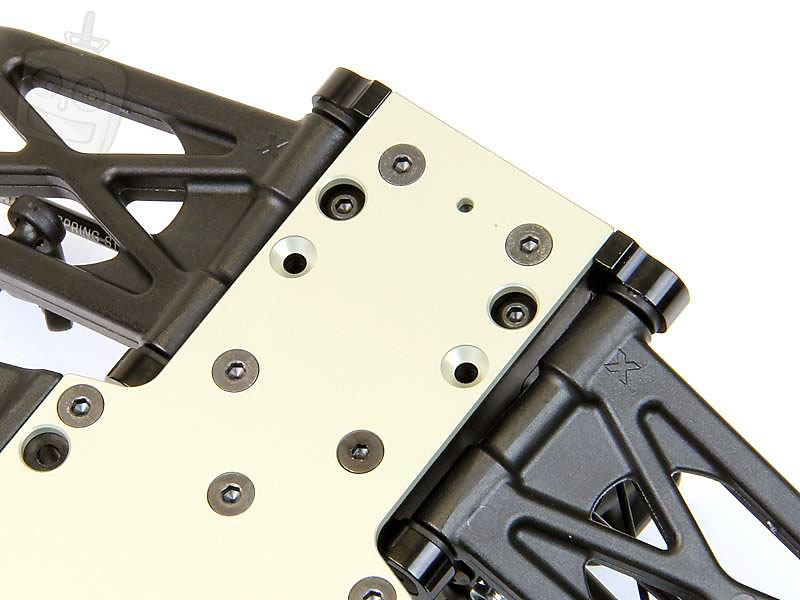
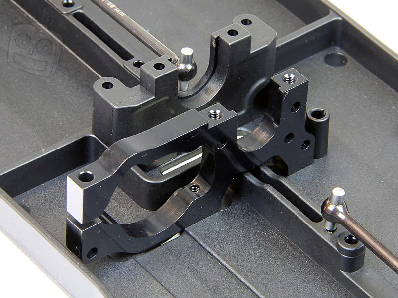
Time to add to the bulkheads. Check out the thickness on these arms! They're reinforced in all the key areas and with the use of Xray's in-house developed composites, these shouldn't be breaking any time soon.
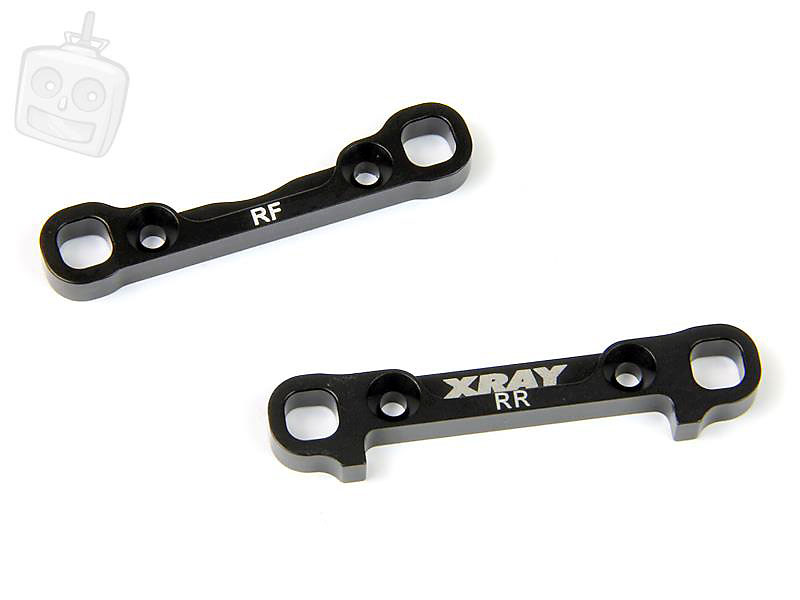
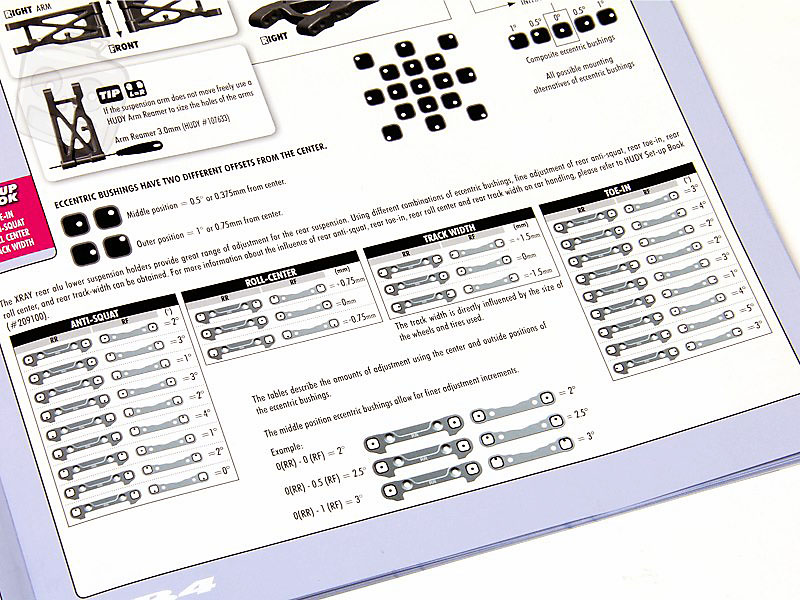
Thick 7075 T6 aluminium hinge pin braces are included as standard on the XB4. Laser etching shows you which brace goes where.
The hinge pin braces use these square inserts for geometry adjustments, plenty of choice!
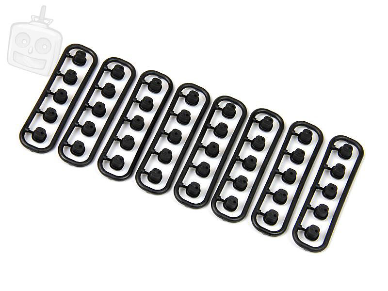
The manual goes into detail on what the different inserts give you when used in different combinations.
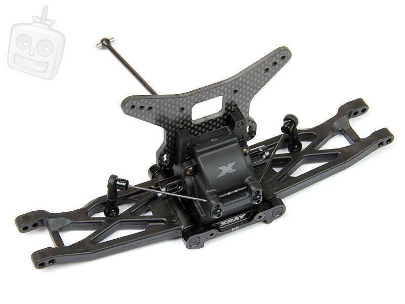
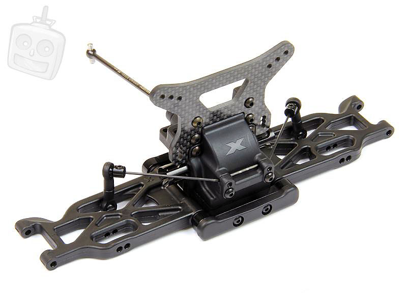
Arms assembled onto the rear bulkhead. With the hinge pin braces fixed down the arms move very freely, another bit of reassurance into the quality and precision that Xray manufacture parts and how well the kit goes together.
Sway bar installed. The sway bar links pop onto the arms which have a ball moulded onto them, this will make diff removal that little bit easier by eliminating 2 screws from the equation. The sway bars are laser etched to denote which thickness they are too.
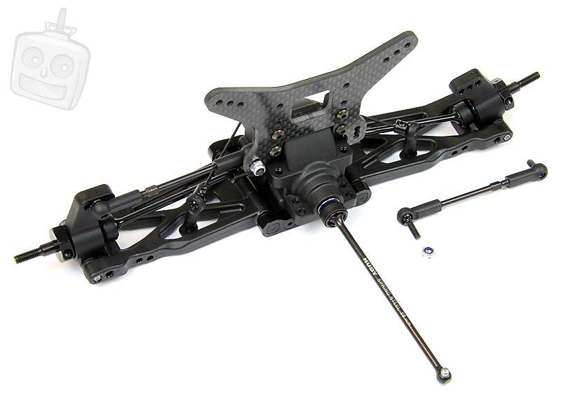
And here's the front end, same as the rear except the addition of a composite front bumper.
Rear driveshaft and hub assembly. More use of Hudy Spring Steel in the driveshafts which use the same plastic ring to retain the pin. The hubs are composite and rather chunky, they're also bi-directional.
An oversized bearing is used on the outside to carry the load better and it's finished off with a clamp on aluminium hex hub, 14mm in size.
Xray offer two alternative hubs already, you can go wider with the +.75mm option or narrower with the -.75mm option hubs.
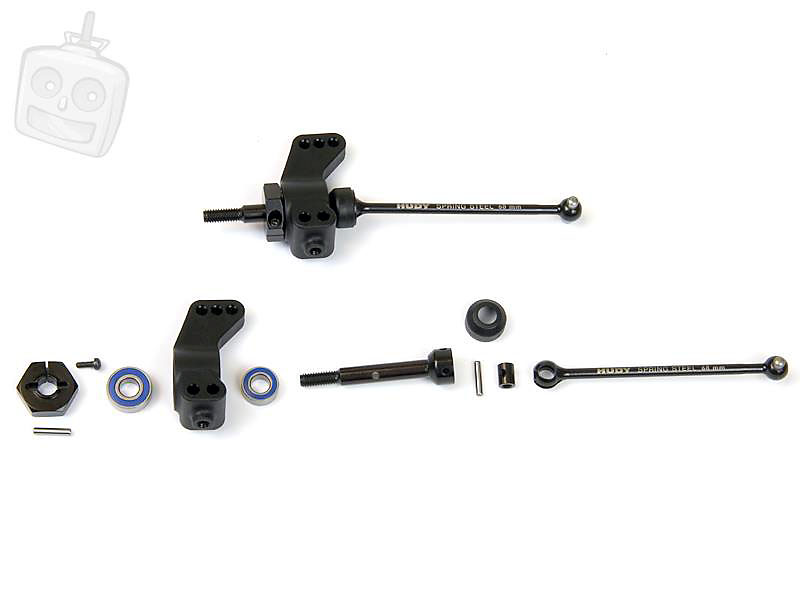
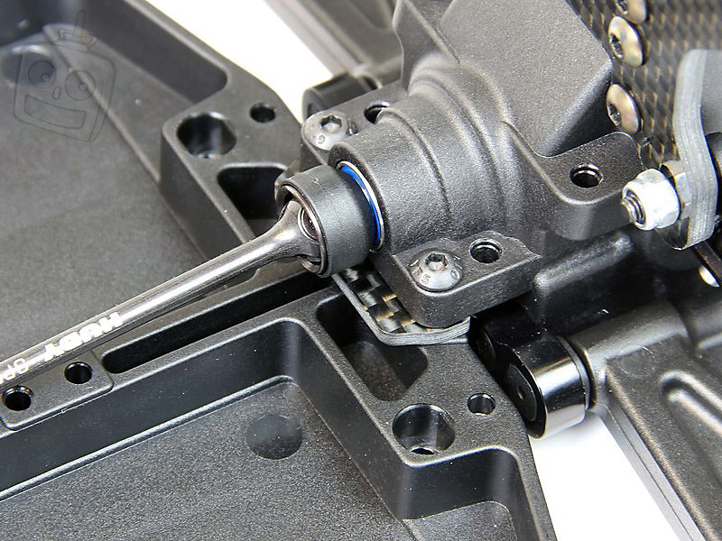
Here's a shot of the rear driveshafts and hubs on the rear end. The outer hingepin features a machined section in which a grub screw captures it from underneath the hub, a few turns of the grub screw allows the pin to be released and the hub removed.
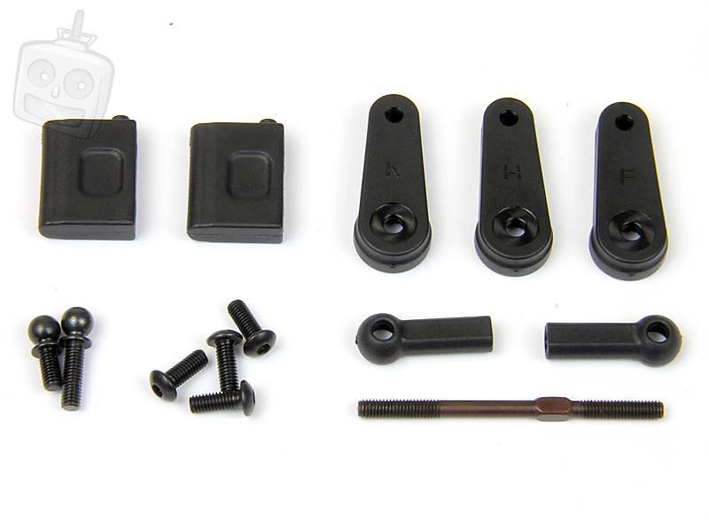
More Hudy Spring Steel, this time in the form of the turnbuckles. The rod ends feature a hole on the outside that allows you to unscrew the ball end from the car rather than popping off ballstuds each time.
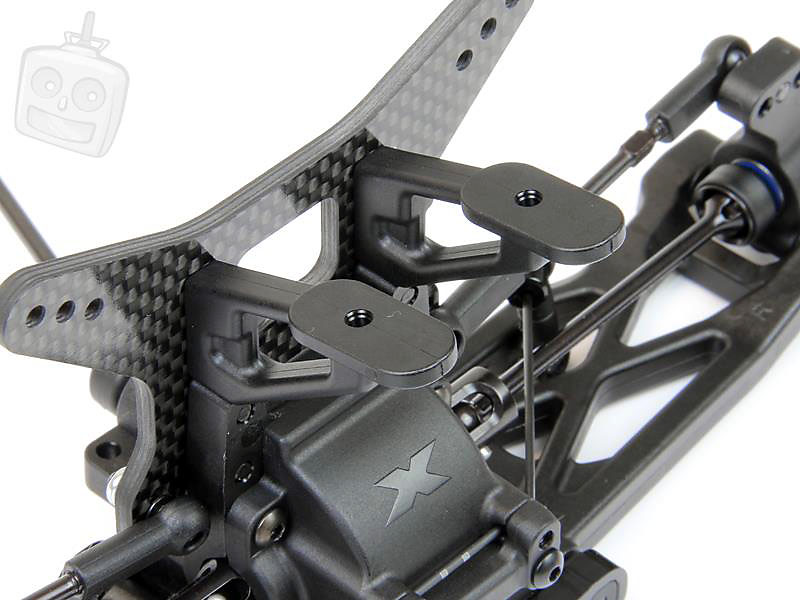
More use of chunky plastics! The rear wing mount is very solid.
You'll also notice on the wing screws that the plastic is slightly chamfered, this means that using a screw on the plastic for the first time is much easier and Xray have chamfers on virtually all the plastic parts across the car, yet another little bit of attention to detail that sets Xray cars apart from the rest...
Rear end fitted to the chassis. The parts all key together perfectly!
4 Screws hold the rear bulkhead in, two button screws are also used to ensure the gearbox stays together securely.
The gearbox can be removed without taking the button screws out saving time during maintenance or setup changes.
A carbon fibre spacer is used when fixing the rear gearbox to the chassis.
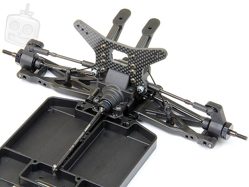
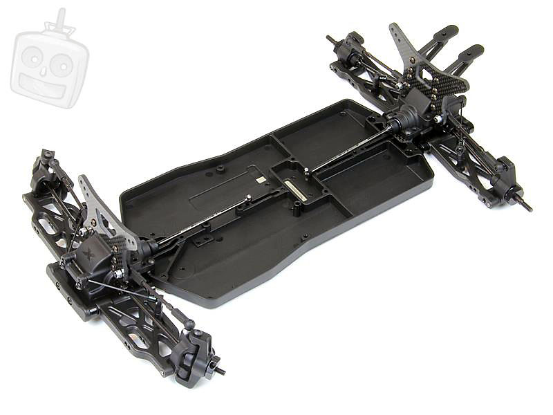
Front and rear ends installed onto the chassis.
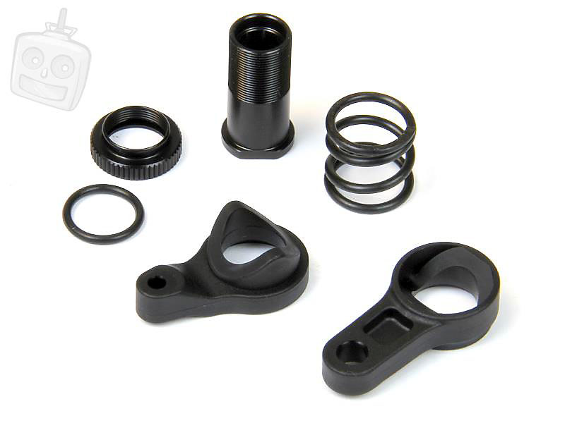
Time to assemble the servo saver, it's basically a scaled down version of a 1/8 servo saver.
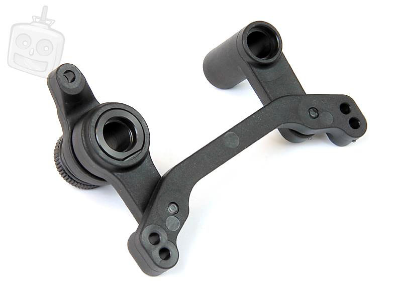
Steering assembly installed onto the chassis. The ackermann plate features two holes for the steering links and a carbon fibre bridge strengthens the assembly on the chassis.
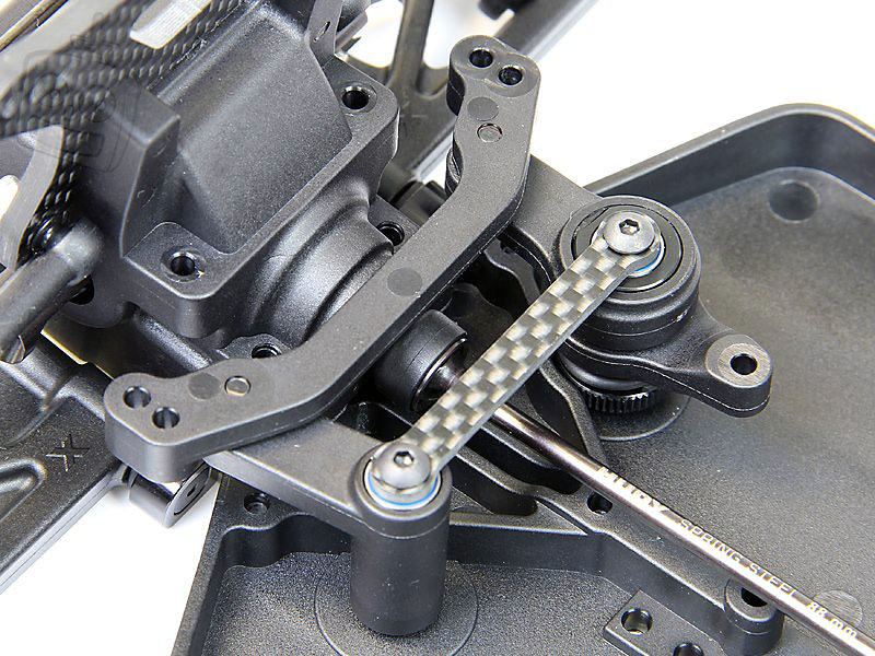
The steering links use aluminium washers to set the bump steer.
Slipper time! All the parts here are very high quality, aluminium, spring steel parts and even heat treated pins...
The completed slipper assembly. This goes together extremely well, just like the rest of the car.
Adjustment is simple and a grub screw clamps the adjustment nut down to stop unwanted loosening of the slipper when in use.
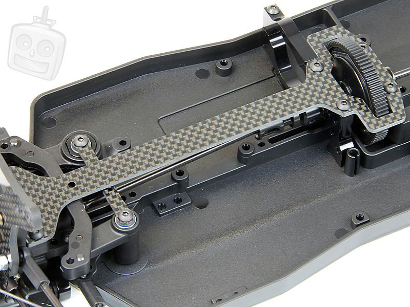
Time to get this slipper installed. More carbon fibre is used for the top deck and 7075 T6 aluminium for the motor mount.
Yet again all the parts fit perfectly and a couple of screws later the center bulkhead is installed and ready for the slipper assembly.
Top deck fitted. The top deck sits flush against the top of the bearings used on the slipper assembly. This eliminates the use for spacers or more plastic parts to hold the bearings in.
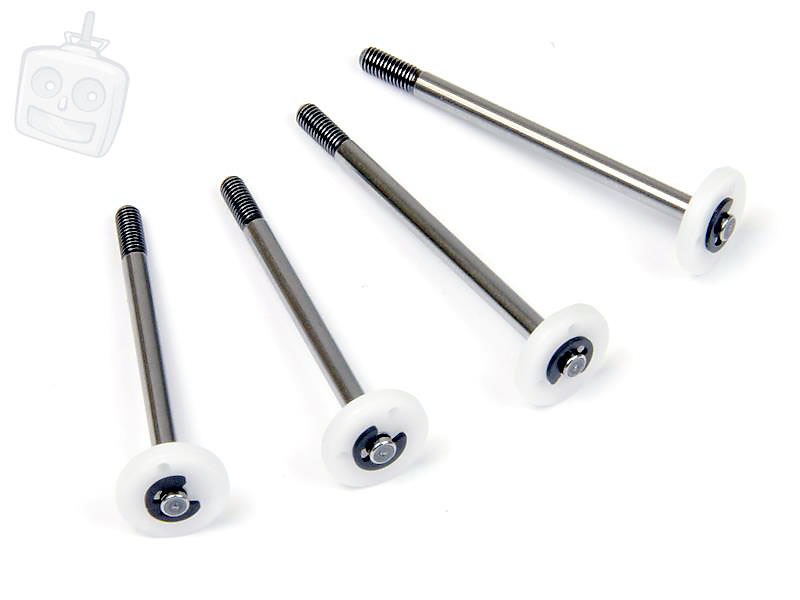
Time to build some shocks. Hardened shock shafts as standard with moulded Delrin shock pistons and guides. You get plenty of choice out of the box allowing you to play around with setups at no additional cost.
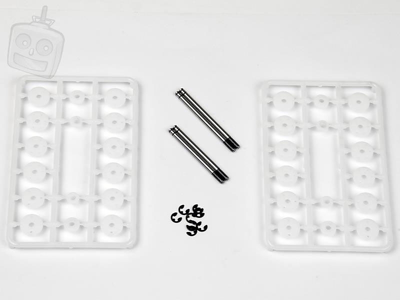
The pistons are fixed on using two e-clips. Fiddly things!
Here are the shock bodies and lower caps, both aluminium and big bore too.
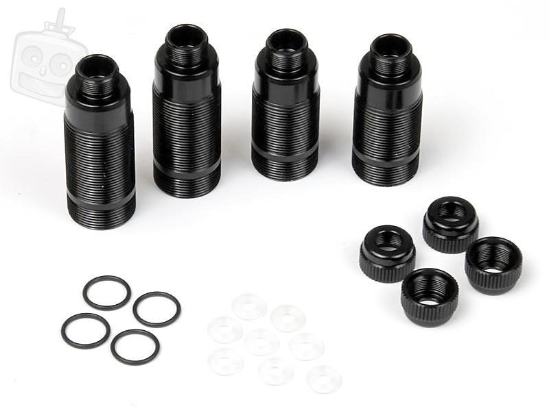
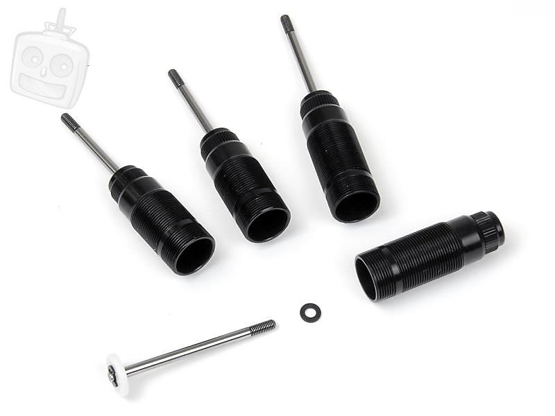
The shock caps are a moulded composite, this'll surely put off some people but they are pretty chunky and look solid. They are also bleeder caps making shock assembly that bit easier.
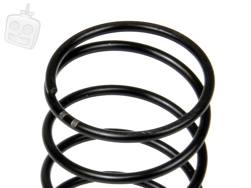
Xray also use their own in-house made springs which are matched up as pairs to ensure consistency.
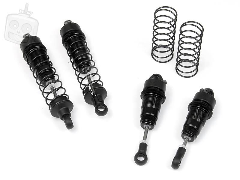
As you can see here, the springs are laser etched to show which type they are, this saves having to paint the spring or mark it in other ways. A simple but effective solution.
Here are the front shocks installed. A steel mount is fixed to the shock tower to stand the shocks away.
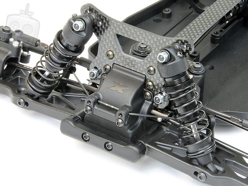
Rear shocks installed.
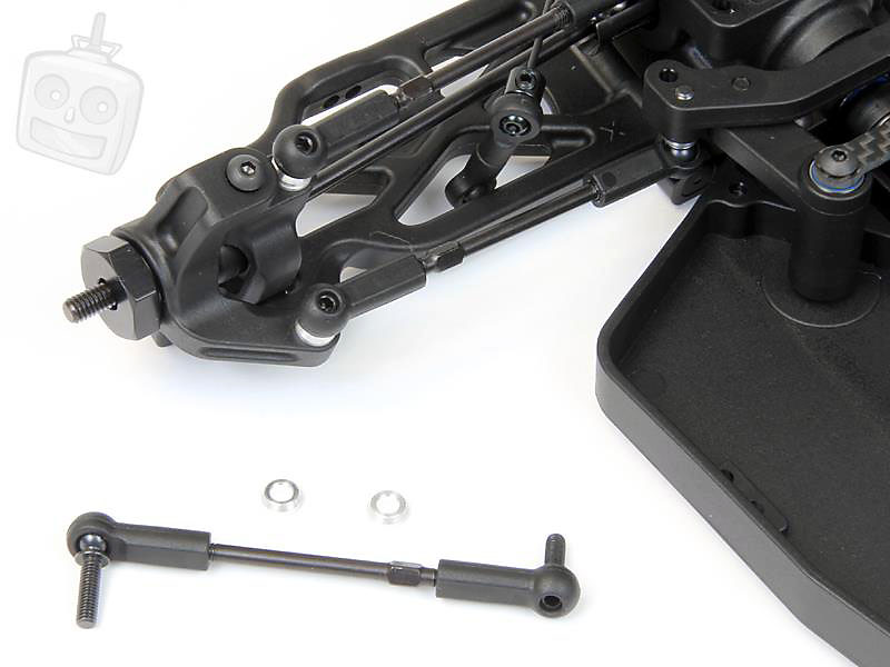
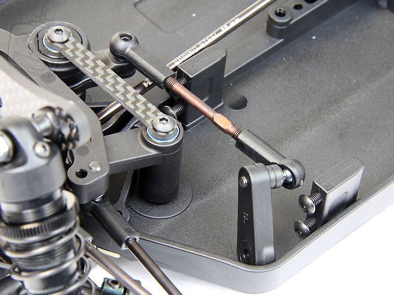
The servo mount and link is pretty simple. Two plastic blocks for the servo and a basic turnbuckle for linking it to the steering system.
The servo mount and link installed. We're not installing any electrics into this model so it'll look a little bare!
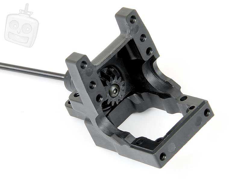
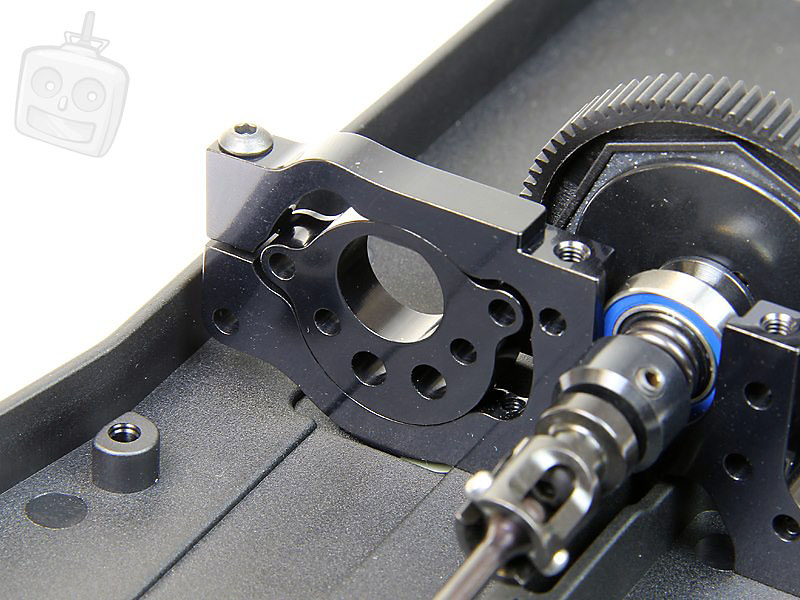
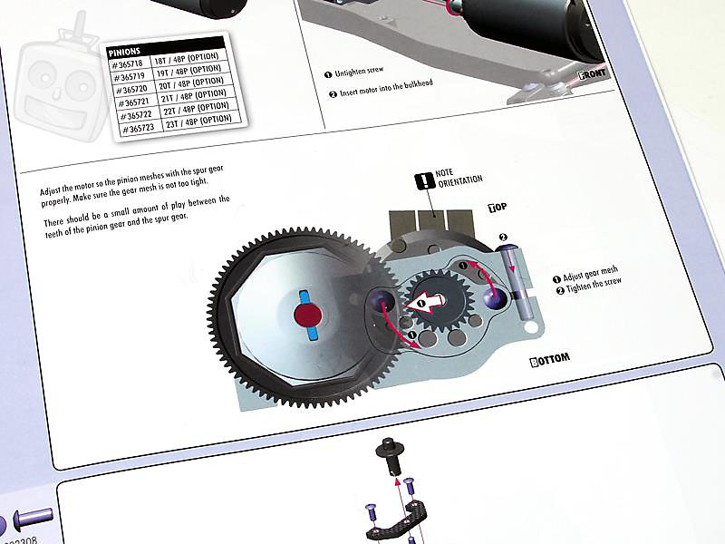
The cam type motor mount is great. You fix this to the motor which then slides into the mount, by turning the cam in the mount you can precisely set the mesh and secure it with one screw.
Here's a diagram on how to set the mesh, a very simple system
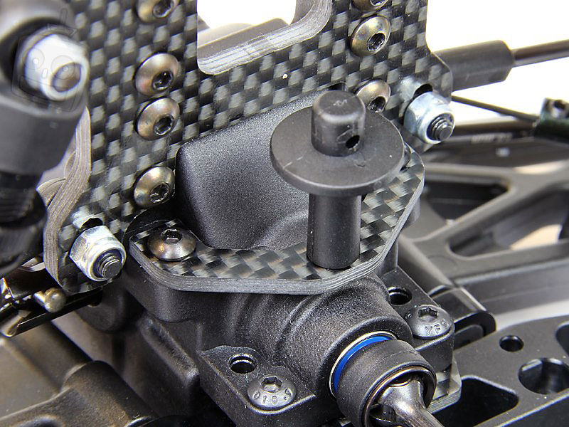
The rear body mount fits onto a carbon fibre plate, a nice little touch.
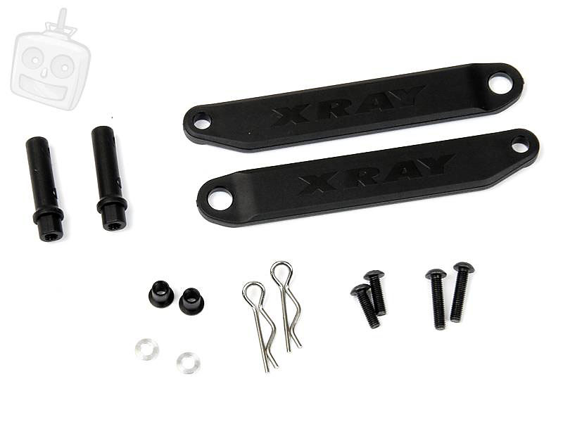
Here are the battery straps and posts.
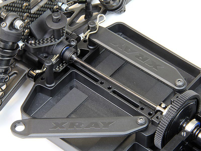
Once installed the straps easily move with the use of one body clip, once unclipped the strap pivots out 90 degrees.
This small plastic bridge is used to keep the motor/ESC wires tidy and out of the way.
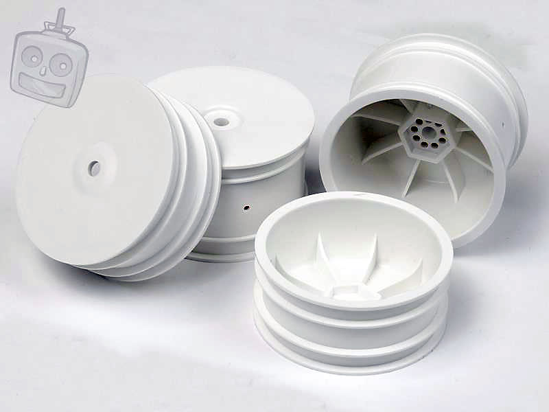
Xray supply their own Aerodisk wheels, with 14mm hex.
Almost there!
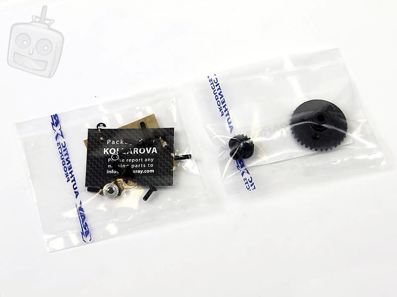
A spare crown and pinion gear is included in the box and you also get a selection of screws and nuts just incase you lose anything or need to replace a fixing.
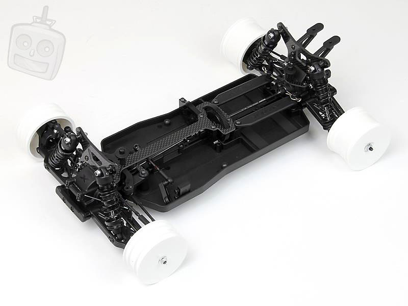
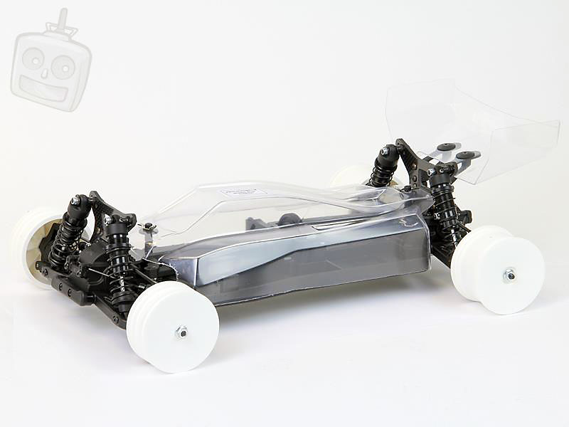
And here she is finished with the body shell and wing on. I'm a big fan of this body, it's a sleek cab forward design and I look forward to seeing some pretty cool airbrushed designs on the XB4.
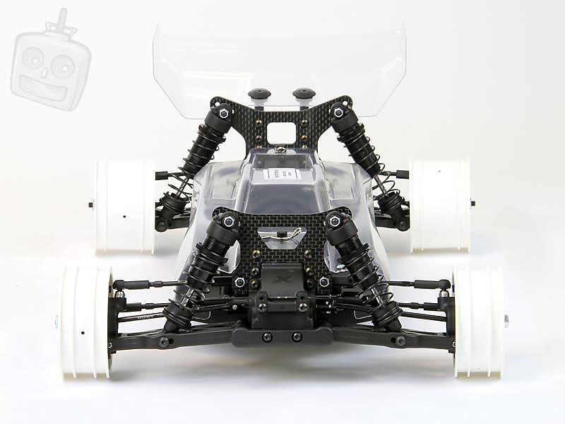
Front end view, expect to see this behind your 4WD soon.... :)
And that concludes the build of Team Xray's XB4. Thanks for looking, we hope you enjoyed it!
Source:

http://www.facebook.com/jemodelsrc
|
