|
- X-6 CUBED ASSEMBLY INSTRUCTIONS -
Previous - Table of Content - Next
B4.2 DISASSEMBLY
GENERAL
1) You are too experienced to require photos for these first few instructions. Remove the body. We suggest you store the clips by putting them back in the body mounts. Remove the wheels. Again, store the nuts by putting them back on the axles. We store things this way often so they are right where we need them when we are looking for them.
2) Remove the gear cover. You will not need this part or the screws. Take the pinion off the motor, then unsolder and remove the motor. Of course you'll need these parts again, so we suggest you put the pinion with your other pinions and put the screws back in the motor for storage.
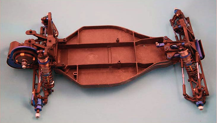
3) Remove the electronics, including the battery, servo, E.S.C., radio receiver, and antenna. Save them all for re-use. Do not remove the servo mounts from the servo, just remove the two flat head screws from under the chassis and save those screws by putting them back into the servo mounts. Disconnect the servo link from the bellcrank, leaving it attached to the servo horn. Do not disconnect the horn from the servo. We suggest you clean the servo tape from the electronics. You should now have a rolling chassis as in this photo:
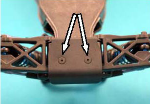
4) From beneath the chassis, remove the two flat head screws which hold the bumper to the chassis & bulkhead. Save the bumper and screws for re-use.
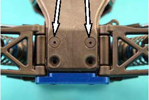
5) Still working beneath the chassis, remove the two flat head screws which hold the bulkhead to the chassis. Save these screws for re-use.
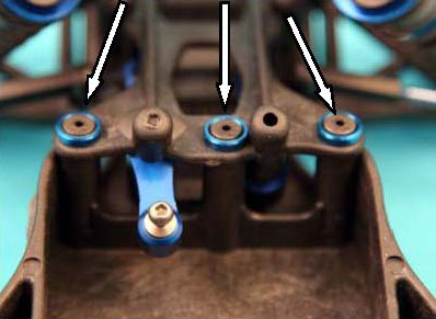
6) From the top, remove the three screws and washers that hold the top plate to the chassis. Save the screws for re-use.
7) Carefully remove the front suspension and steering assembly and set it aside for re-use. Make sure the steering linkage stays in place.
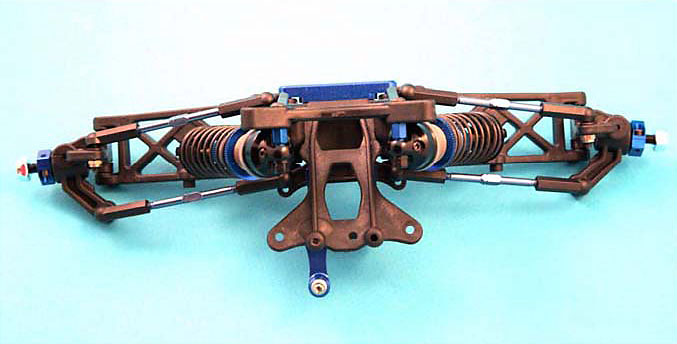
Front end is done! Let's do the driveline.
C.V.D.S & HUB CARRIERS
8) Remove the rear shock assemblies. From each side, take out the bottom bolt, then remove the plastic nut from the top. Save shocks and their bolts & nuts. Donít lose the aluminum bushing in the bottom shock eyelet! Now remove the upper mounting bolts and bushings. Save everything for reuse.
   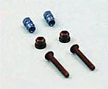
9) Twist the camber link inner ball cups off their ball studs, then remove the ball studs. Leave the cups on the camber links and the links on the hub carriers; save the ball studs and any washers that were under them.
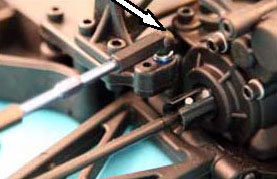 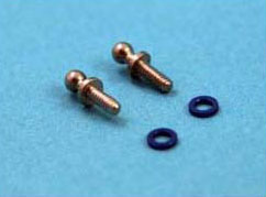
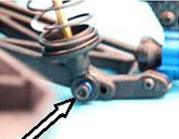
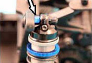
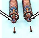
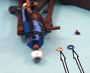
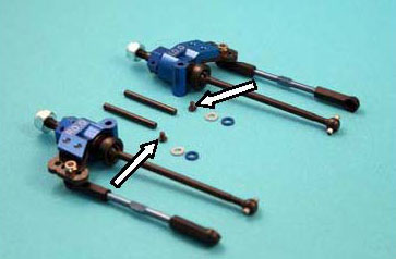
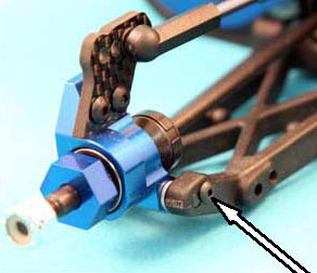 10) Remove the rear hub carriers with the C.V.D. assemblies still in them and the camber links attached to the hubs. Do this by removing the tiny 2-56 button head screw (left photo) and pushing the hinge pin out with an Allen driver. Careful not to lose the shims on the hinge pins! (center photo) Save these entire assemblies for re-use: The hub carriers, shims, hinge pins, and especially those pesky little screws. (bottom right photo) 10) Remove the rear hub carriers with the C.V.D. assemblies still in them and the camber links attached to the hubs. Do this by removing the tiny 2-56 button head screw (left photo) and pushing the hinge pin out with an Allen driver. Careful not to lose the shims on the hinge pins! (center photo) Save these entire assemblies for re-use: The hub carriers, shims, hinge pins, and especially those pesky little screws. (bottom right photo)
TRANSMISSION
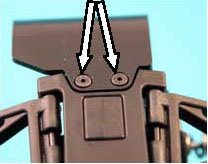
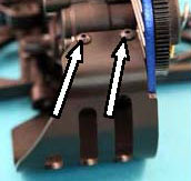
11) Remove the gear cover. Two flat head screws from the bottom and two button heads from the top. Save the flat head screws for Inst. # E14 and the button heads for # F7.
12) Remove the two 5/8" flat head screws that hold the wing mounts to the shock tower and save the screws for Inst. # B1.
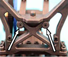
13) Remove the long bolt that holds the wing mounts to the transmission. This bolt will not be used. Remove the left wing mount.
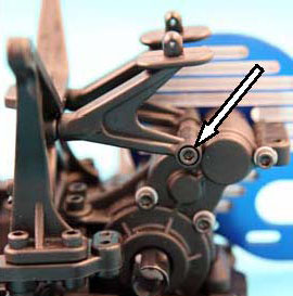
14) Remove the two bolts holding the transmission in the car. Save these 3/8" cap heads for Inst. # D 7 . The transmission should lift out now.
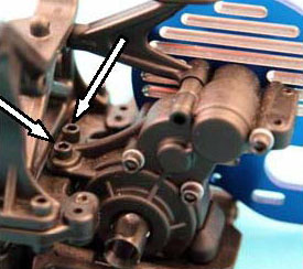 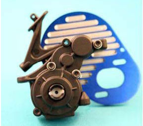
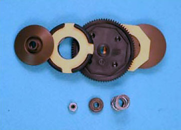
15) Remove the 5-40 nut which secures the slipper assembly, and pull off the nut, spring retainer, spring, outer slipper plate, slipper housing assembly with pads, spur gear, inner slipper pad, and inner slipper plate. All slipper parts will be re-used.
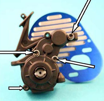
16) Remove the three long cap head screws (long arrows) from the transmission and take off the motor plate and wing mount. Then remove the last shorter cap head screw (short arrow), and separate the transmission case halves. You may discard the motor plate and wing mount; save the long bolts and washers for re-use in Inst. A23 and the 1/2" cap head for Inst # D5.
 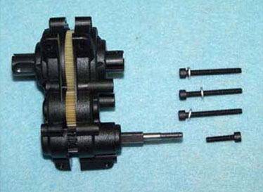
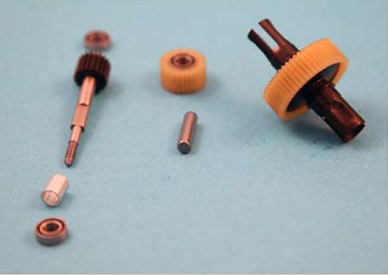
17) Remove the transmission components. The case will not be needed, but you will need the top shaft and spacer, two 3/16" X 3/8" bearings, idler gear with its two 3/16" X 3/8" bearings and shaft, and the differential assembly. The outdrive bearings will not be retained.
OK. Everything you'll need is off the B4.
Now let's build carbon fiber goodness.
Previous - Table of Content - Next
|
