|
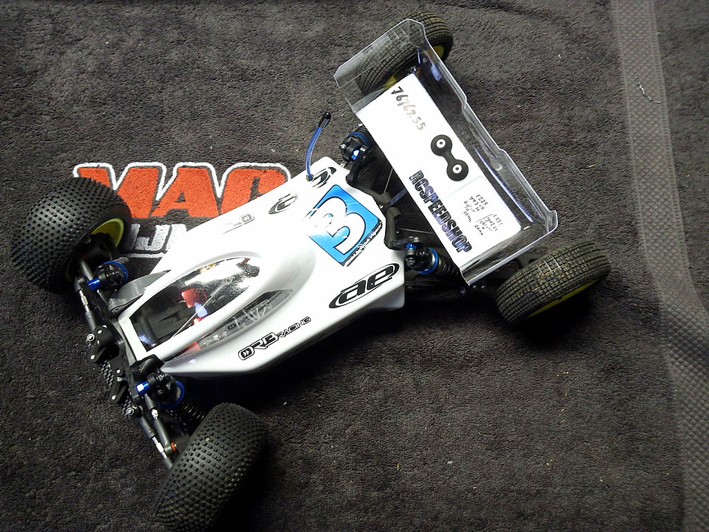
- ORB Forward build by Janus -
Notes/rants/excuses:
In General:
- If you want to tap the holes for the screws, use a no.2 tap
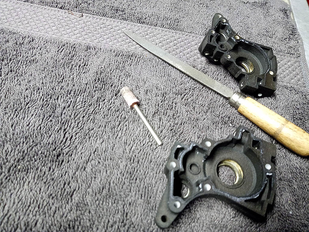
- The 3d printed parts have a grainy surface. For minimal slop in the build use a small file, or Dremel, where parts meet so the surface is flat, and shim parts accordingly.
- It's assumed this is not your 1st. build, so no brainers like “use threadlock on axle” or “seal carbon with glue” are not mentioned
- When using an electric screwdriver, make sure you use a lower torq. setting
- The screws included in the kit are a nice quality.
------------- ------------- ------------- ------------- -------------
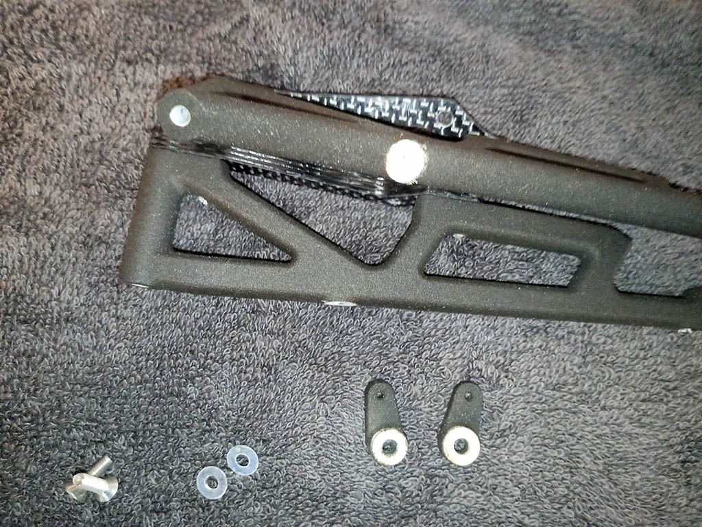
Step 1: "Rotates freely"; read "get ur Dremel out", also added a small 3mm shim to reduce friction
Also used slightly longer screws
------------- ------------- ------------- ------------- -------------
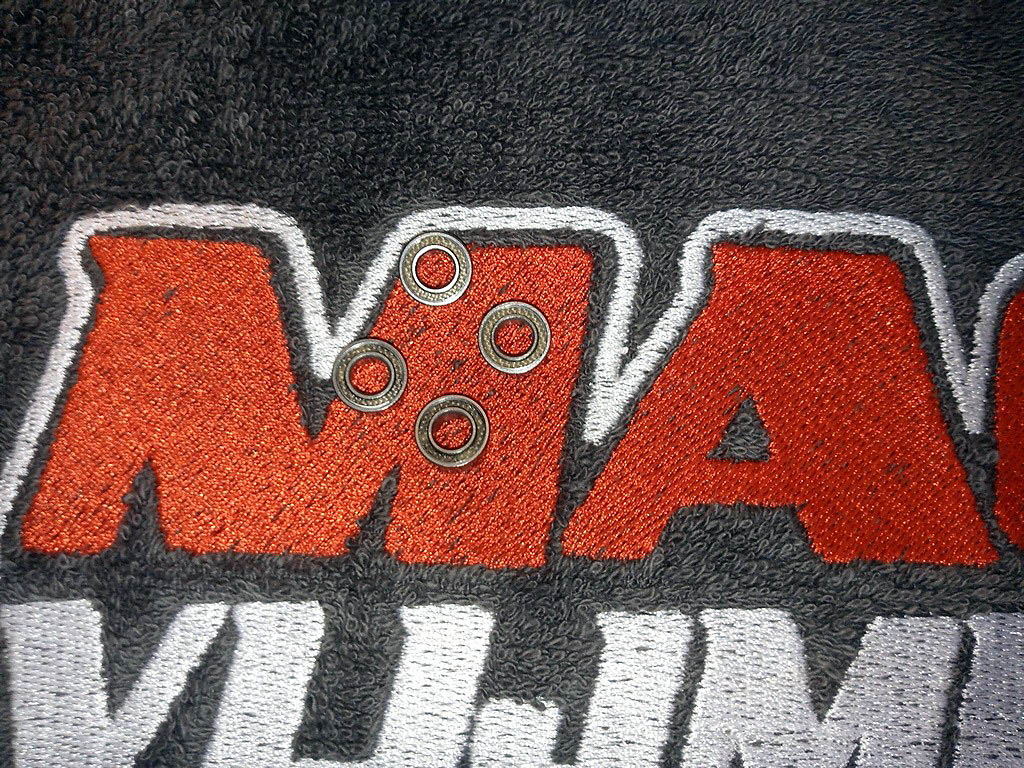
PTFE sealed bearings; for nostalgic reasons :-)
------------- ------------- ------------- ------------- -------------
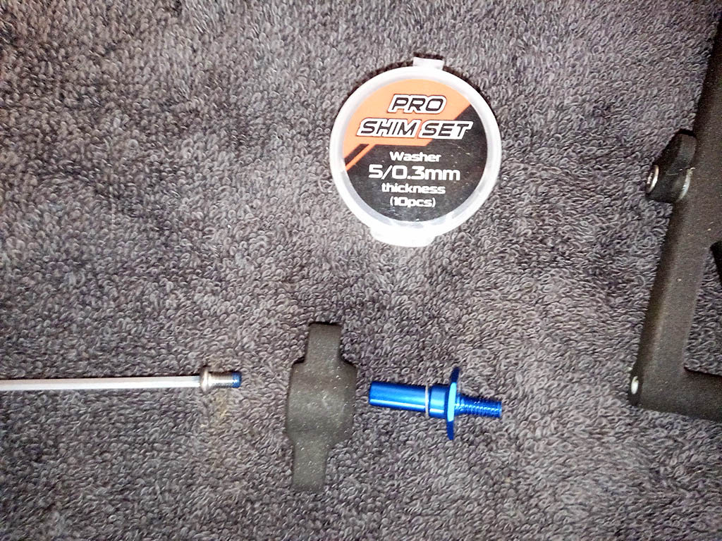
I used a small shim on the axle to reduce axle slop.
------------- ------------- ------------- ------------- -------------
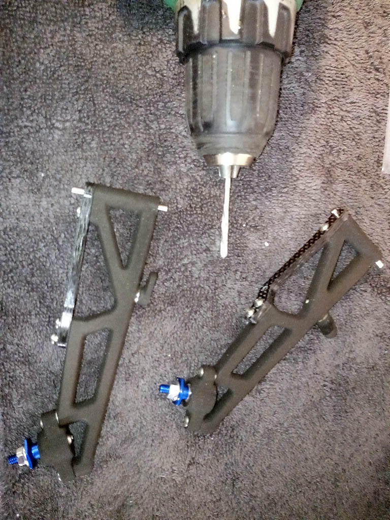
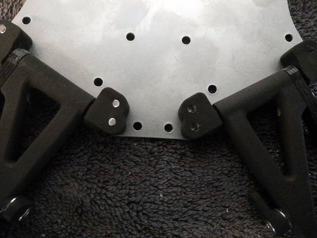
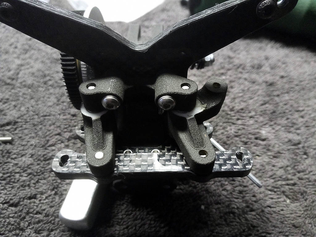
Used a reamer for the suspension mount-plate and wishbones for proper alignment
------------- ------------- ------------- ------------- -------------
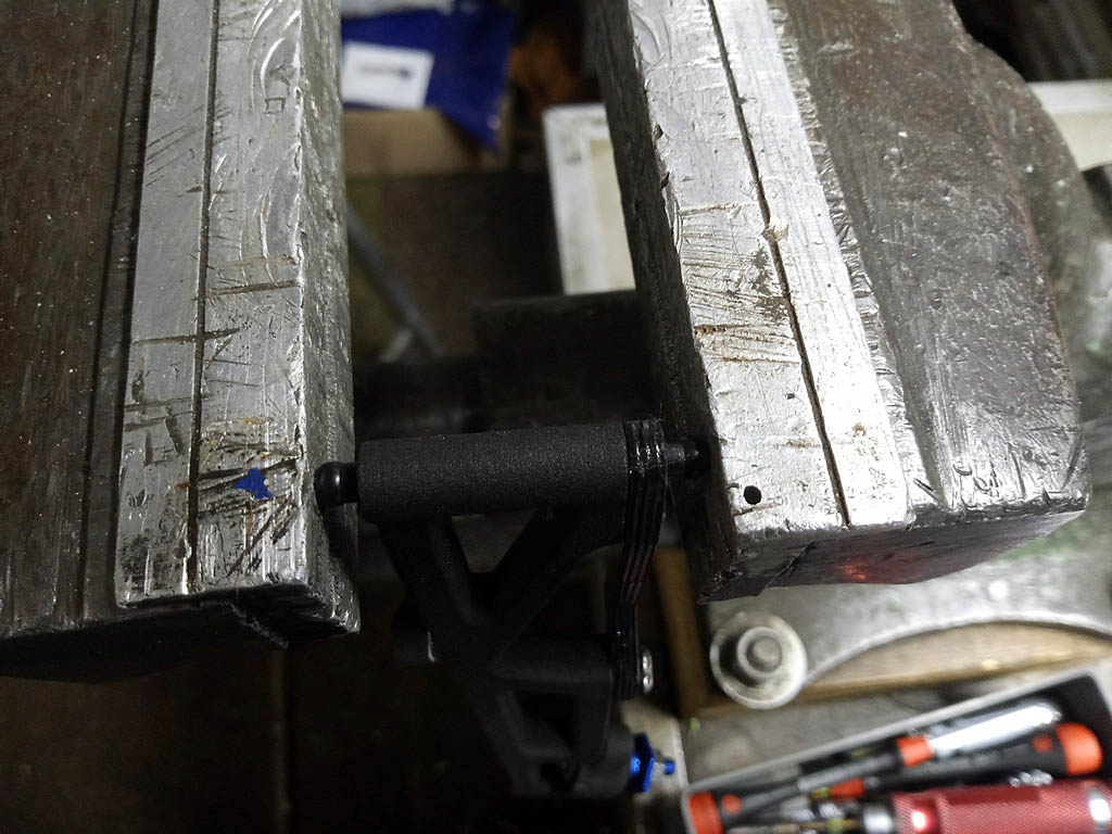
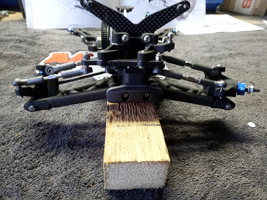
Step 2:The suspension pillows ball are a tight fit. Maybe slightly overkill but I used a vice to ensure all parts were pressed on straight.
------------- ------------- ------------- ------------- -------------
M3x8 are included in the kit for the rear wishbones, but since these parts seem to take a lot of stress I opted for longer screws
------------- ------------- ------------- ------------- -------------
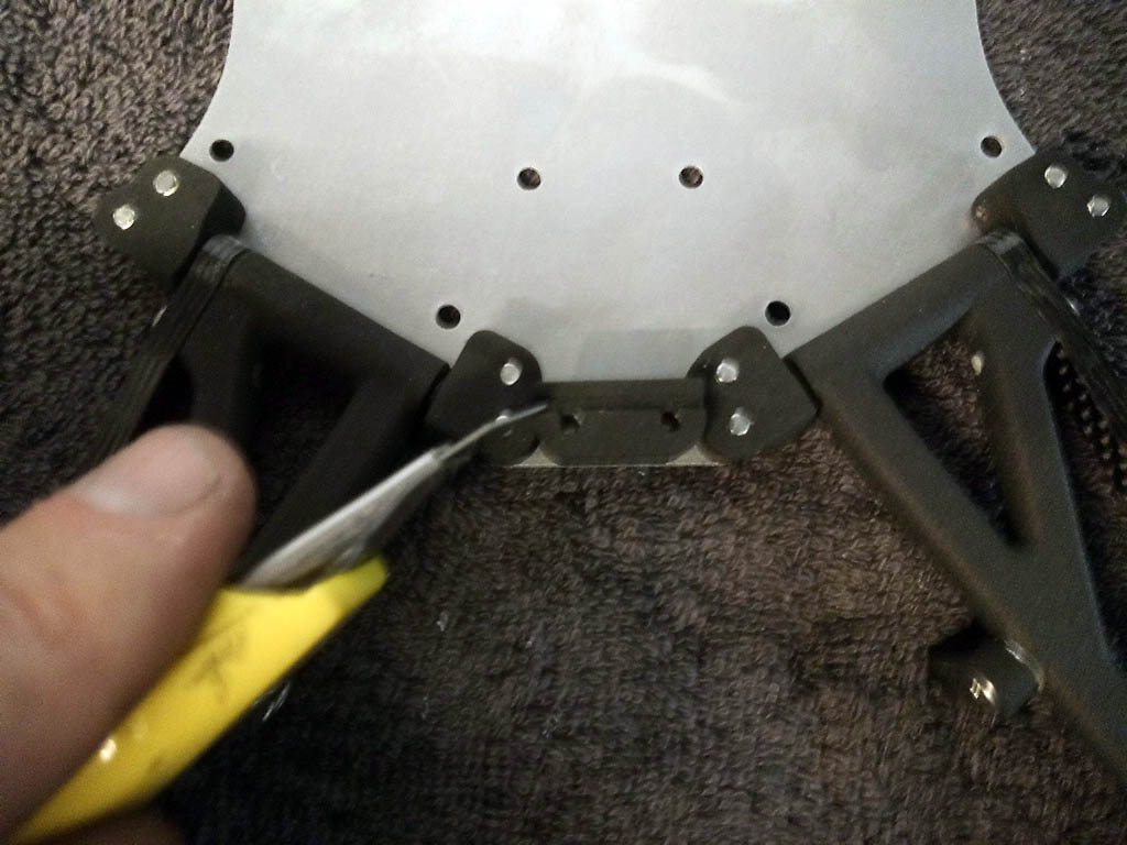
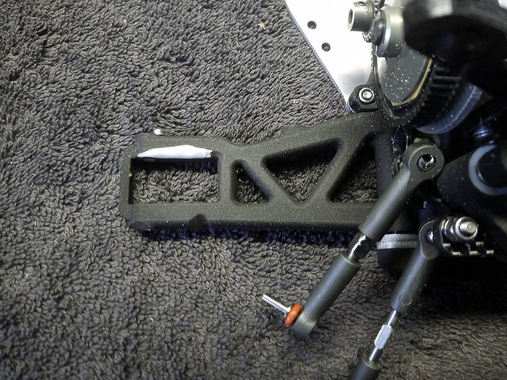
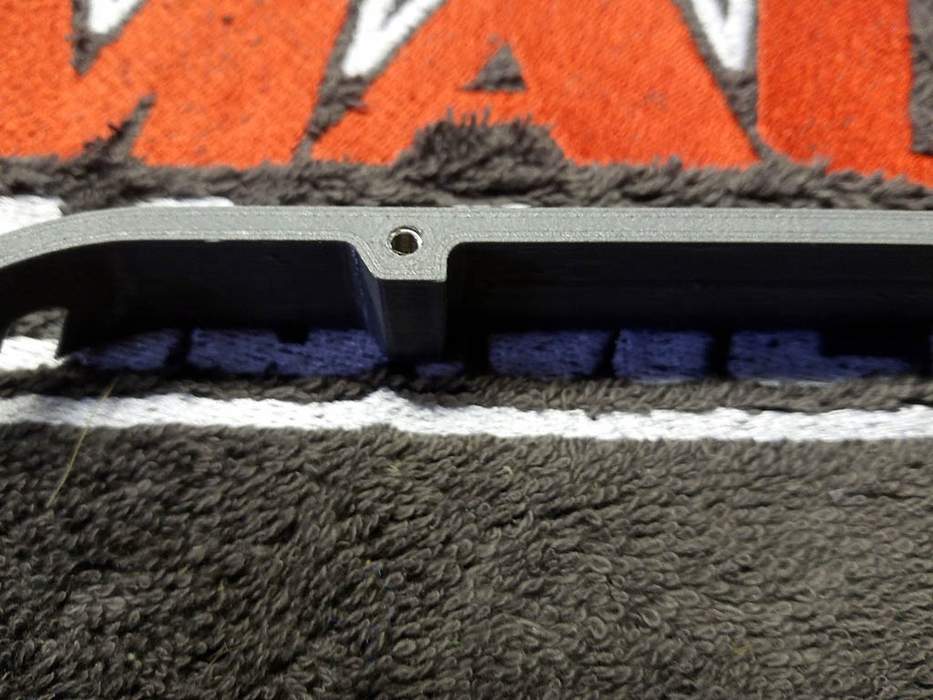
The rear swaybar didn't move freely when nearly flat. To remedy this I cut a small edge of the swaybar mount.
------------- ------------- ------------- ------------- -------------
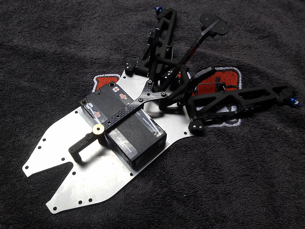
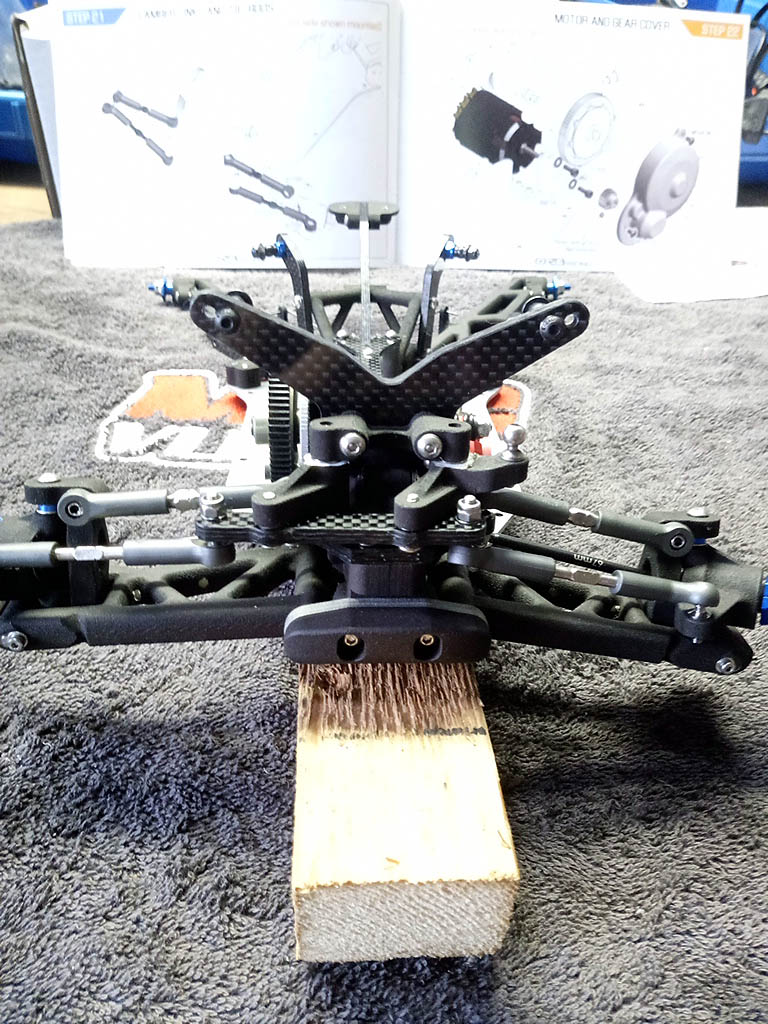
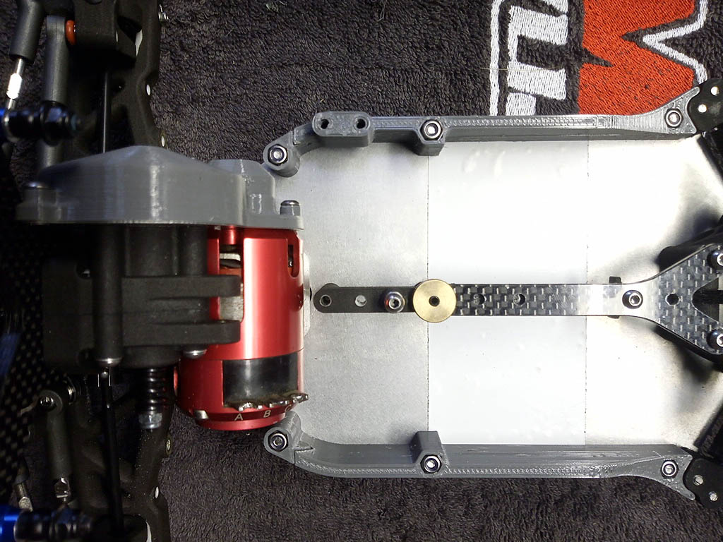
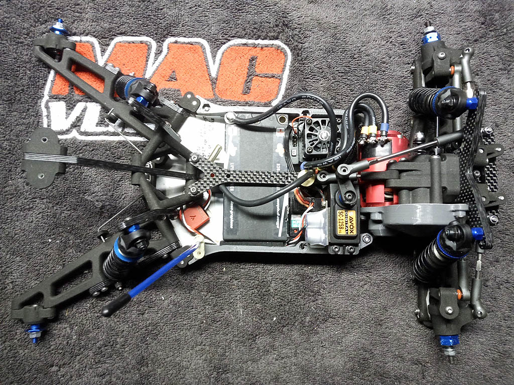
Step 5: LCG conversion ;-)
------------- ------------- ------------- ------------- -------------
Step 7: I actually listened to Paul and used a ceramic thrust bearing.
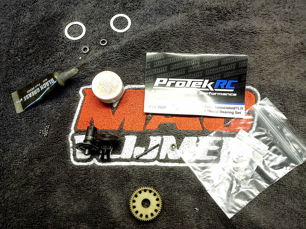 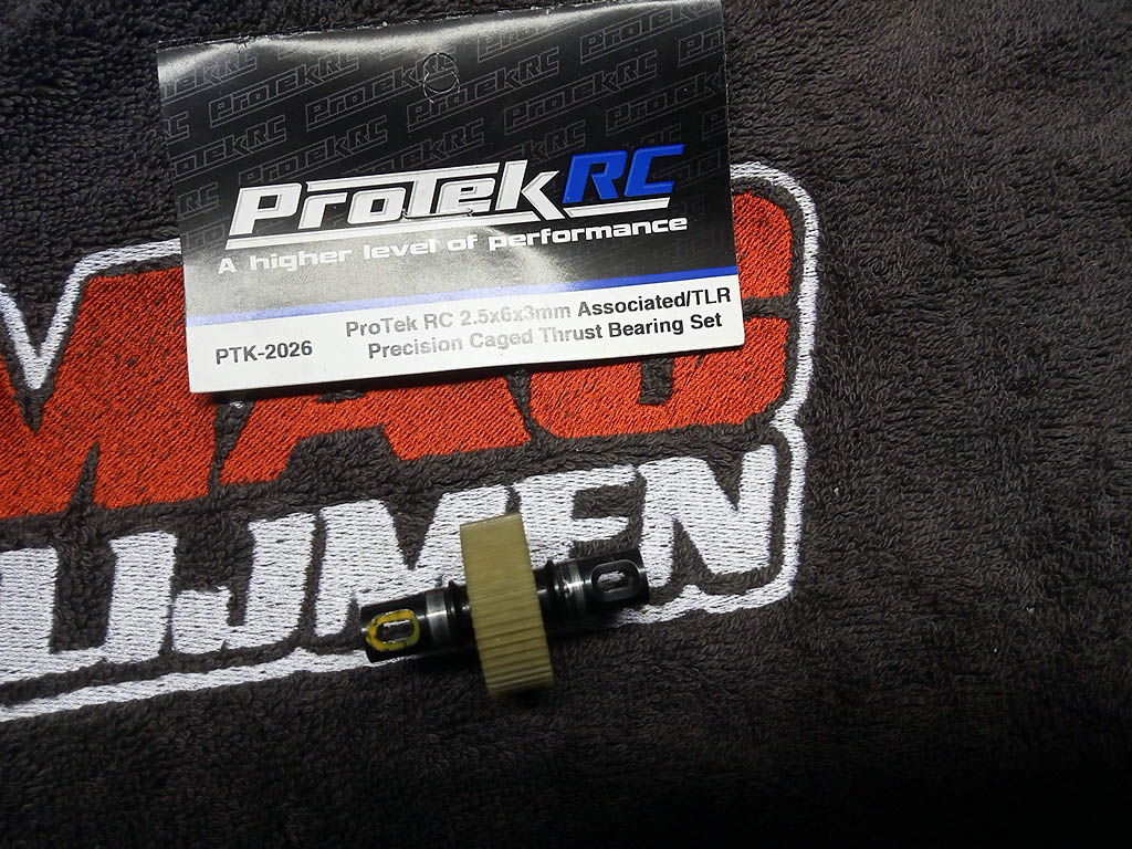
------------- ------------- ------------- ------------- -------------
Moly55, not just for o-rings :-)
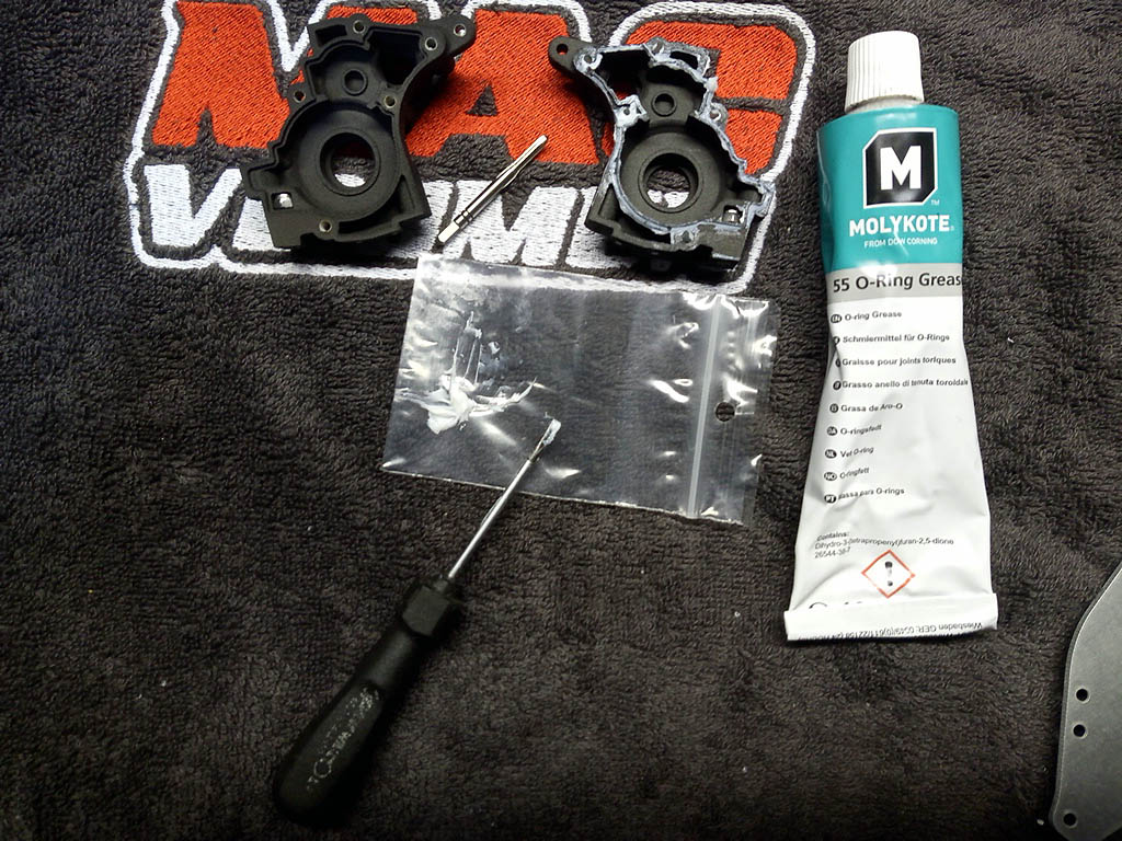
------------- ------------- ------------- ------------- -------------
Step 8: The gear mesh was a bit tight on my casing*. I used a dremel to clean the bearing seatings and make sure I had a smooth surface followed by 30 minutes of running the transmission on a drill to seat the gears. * I know of 2 other builds which did not have this issue, so I'm assuming it's personal ;-)
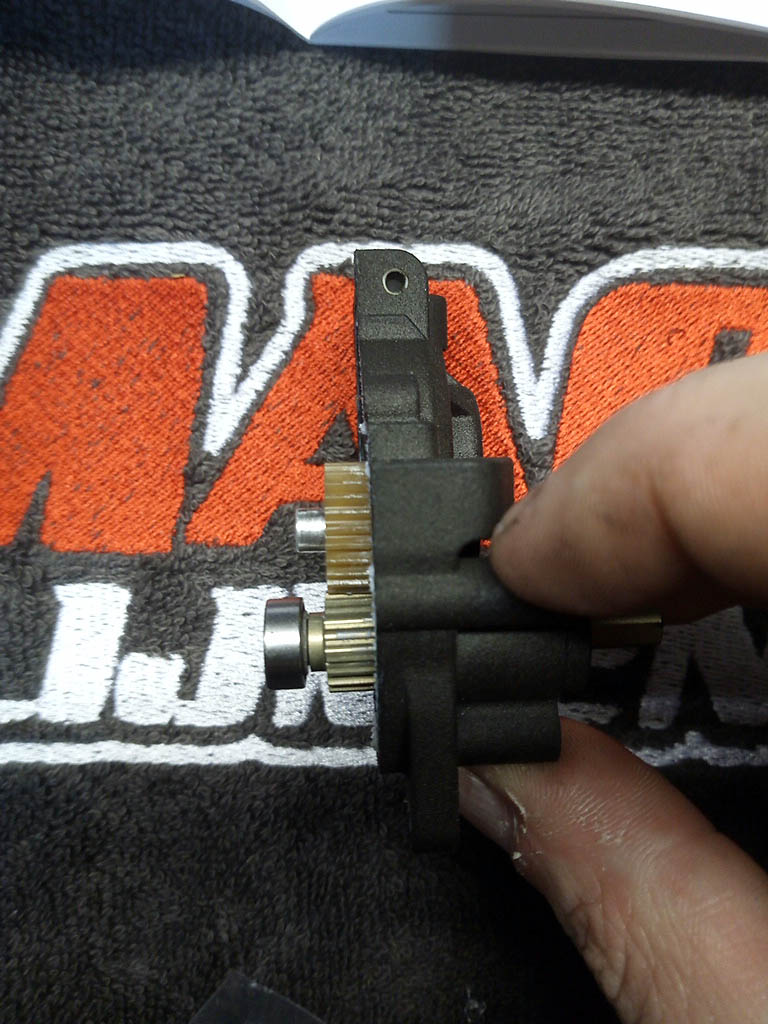 
------------- ------------- ------------- ------------- -------------
Step 10: On a 78T spur I could mount a 24T pinion gear at the most. If you want to go with a higher gearing I would recommend you mount a smaller spur.
------------- ------------- ------------- ------------- -------------
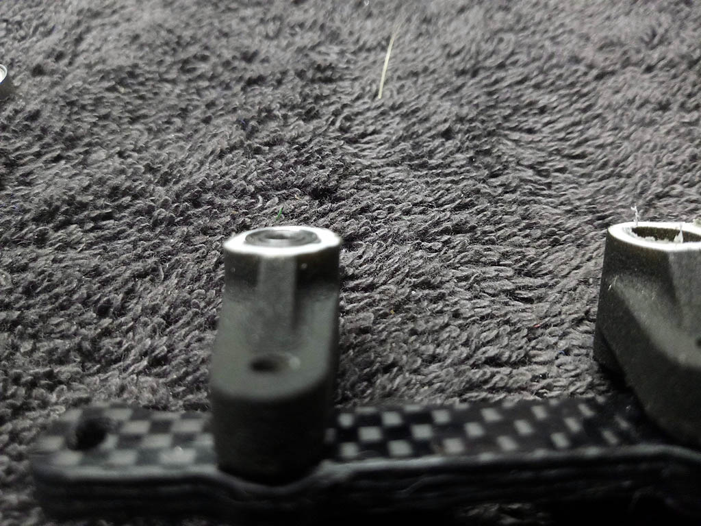
Step 13 & 14: I reduced the height of the bellcranks so the bearing stick out slightly this so ensure smooth steering when the bellcranks are mounted.
In step 13 you need to untighten 2 screws slightly until the steering rack moves freely, it's best to re-check this after step 14 when the steering rack is bolted to the transmission housing. Also used slightly longer screws
------------- ------------- ------------- ------------- -------------
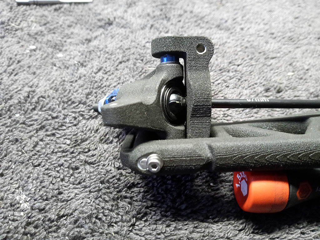
Step 17: The axles take a lot of stress on this car. Make sure you use a lube to ensure the axles lifespan to be as long as possible
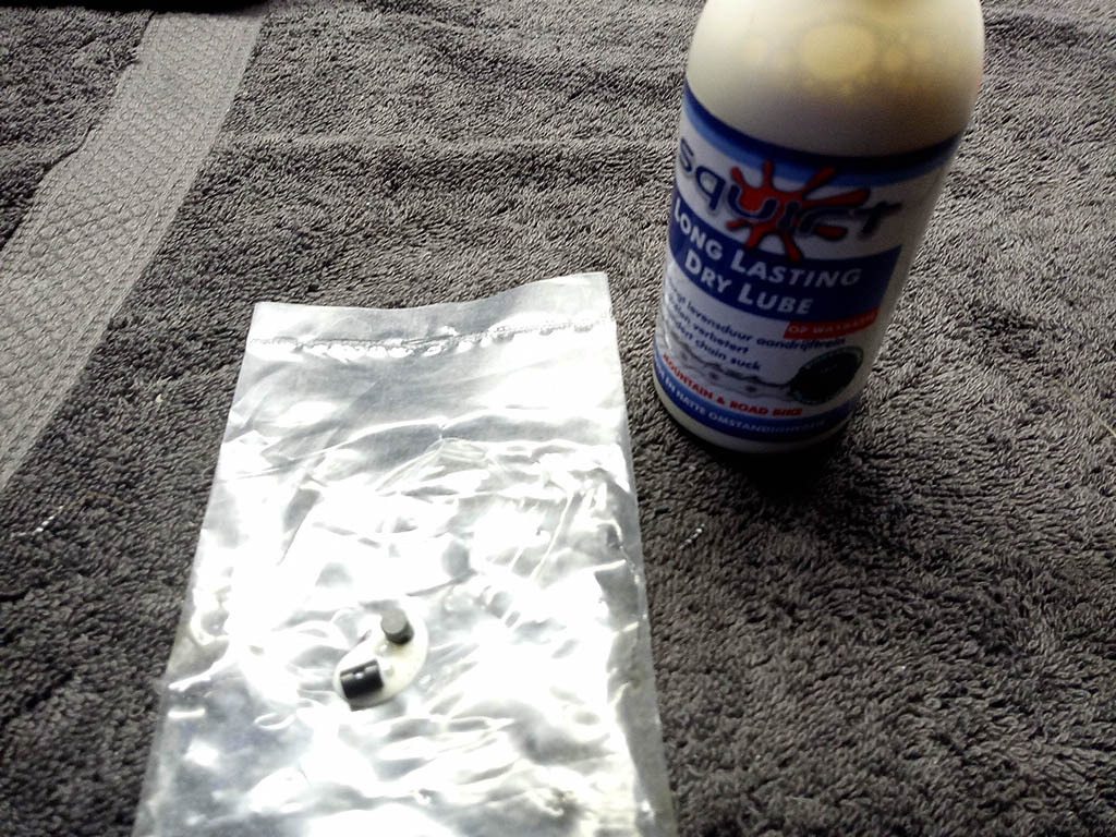
Even though other axles are long enough. It's still best to use the recommended 67mm axles mounted in the 65mm hole location to ensure as much available steering-lock as possible
------------- ------------- ------------- ------------- -------------
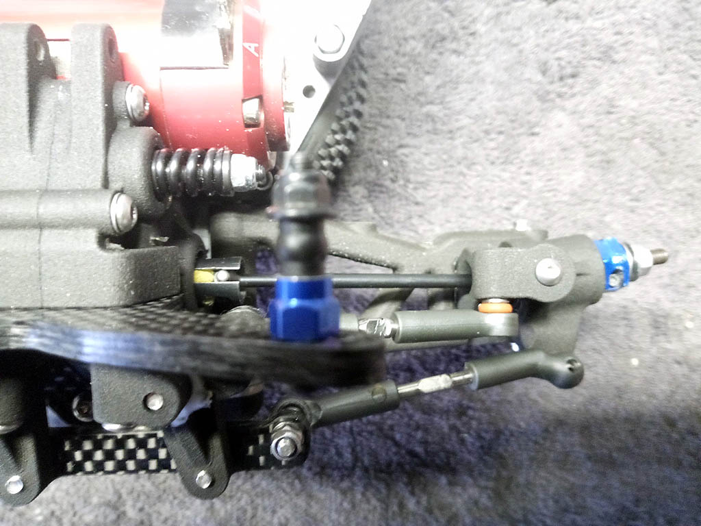
Step 20 & 21: At full steering lock the steering knuckles and wishbones were binding slightly. This resulted in a loss of droop at full-lock.
Used the dremel to remove some material to reduce the binding
 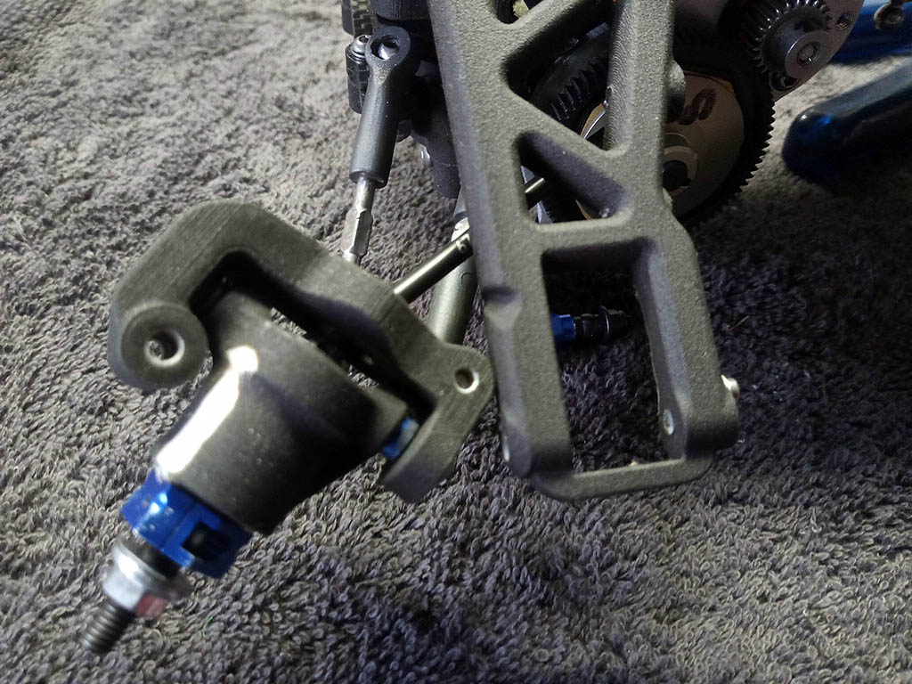
Much better….
------------- ------------- ------------- ------------- -------------
Step 23: You're supposed to use locknuts to tighten down the sidepods, but one one them was rotating in the seating and therefore could not be tightened as you're supposed to do.
I tried gluing the locknuts in place, but the glue had trouble bonding to the plastic. So I went for helicoils instead.
------------- ------------- ------------- ------------- -------------
Step 26: Maybe it's not an issue if you use the recommended B6 ball-cups. But for durability I still prefer the older style B5 ones. With these I had trouble reaching the desired length when using the included steering rod. But the solution was quite simple by just cutting a millimeters of one the ball-cups.
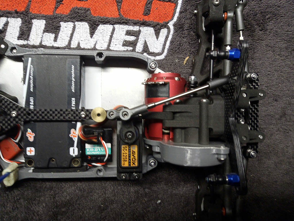
Note: Pro-/tip from Paul: Due to the large stress on the servo-horn an aluminum version is strongly advised
------------- ------------- ------------- ------------- -------------
Various side notes: No antenna mount in the car, that had to be rectified ;-)
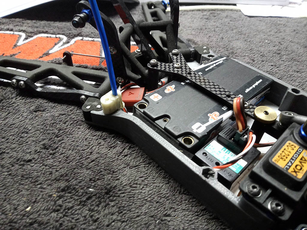
------------- ------------- ------------- ------------- -------------
TLR 22T (truck) front springs fit nicely
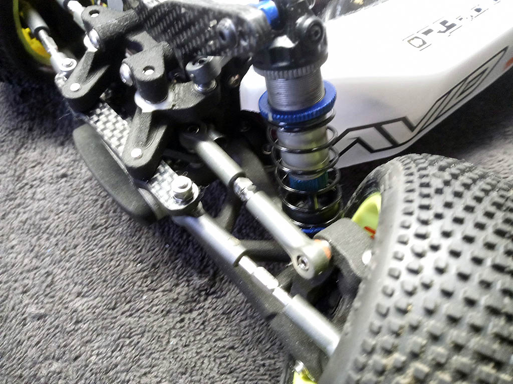
------------- ------------- ------------- ------------- -------------
Step 25 provides a mount for the capacitor of the ESC, but this demands the removal of the ESC fan. I opted to move the capacitor behind the servo just above the receiver.
------------- ------------- ------------- ------------- -------------
|
