|
Ticks a lot of boxes for me:
- It's a kit
- A 4wd that takes stick packs
- Clever motor mount
- Compatible with a lot of the D4 drivetrain.
A few negatives:
- No slipper
- Rear wheels use regular dogbones
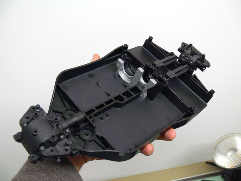
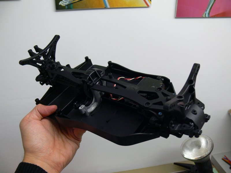
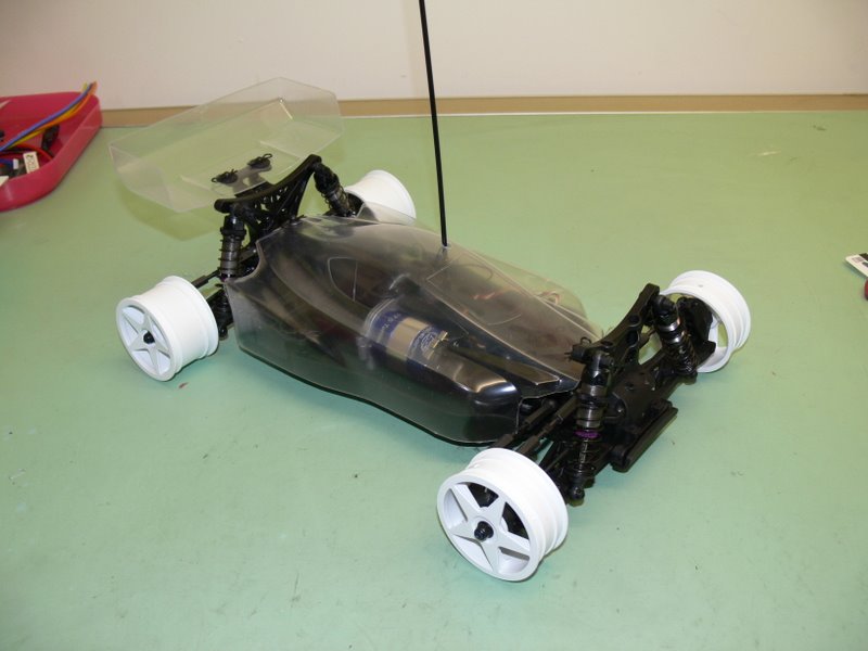
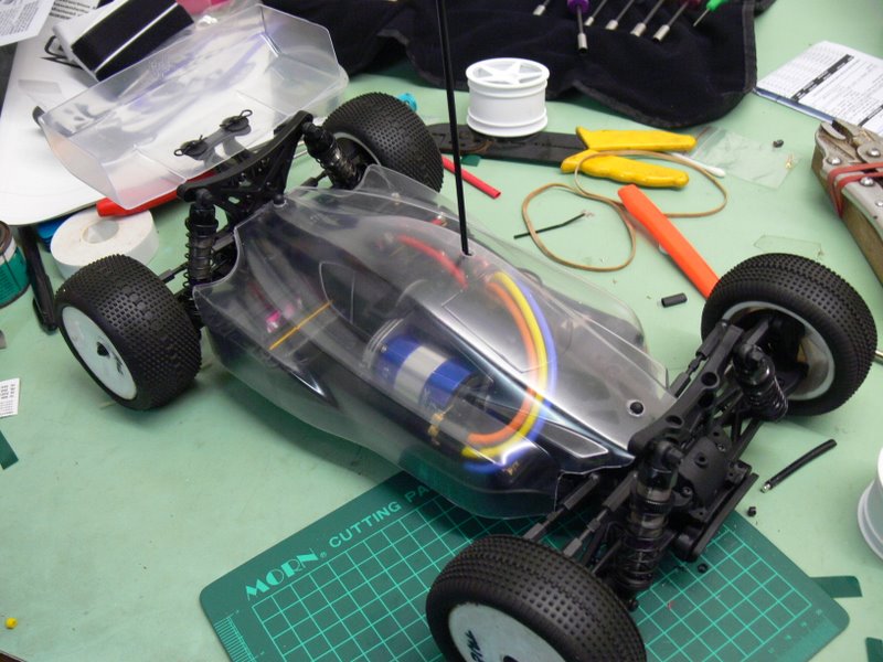
First impressions are the
plastic parts are of excellent quality. The chassis is well moulded,
very flat with no extreme flashing.
Can't really comment on how well it goes just yet. Need to build it
first.
In regards to cost, once you add a set of rear CVD's, slipper, titanium
turnbuckles and metal shocks, it's about the same cost as a B44.
In regards to building CVD's are there any tricks to stop the pins from
falling out? The manual suggests using rubber cement. Any other
solutions that have proven to work?
DAY 1
Up to page 17 now. Only one real surprise so far - no bearings were
included for the diffs, only bushings.
Also lost an e-clip while working on the front gearbox. Would've been
nice to have a spare or two.
Wondering whether I should apply diff lube to all the dogbones as per
the manual. In my experience, this just gathers dirt and causes more
damage.
Found a few good ideas on CVD's. Best solution I like so far is adding a
few layers of heatshrink over the CVDs. Thinking of doing this in
addition to threadlocking the pins in place.
DAY 2
Now up to page 21/34. Just finished building my first set of CVD's.
Fiddly little things.
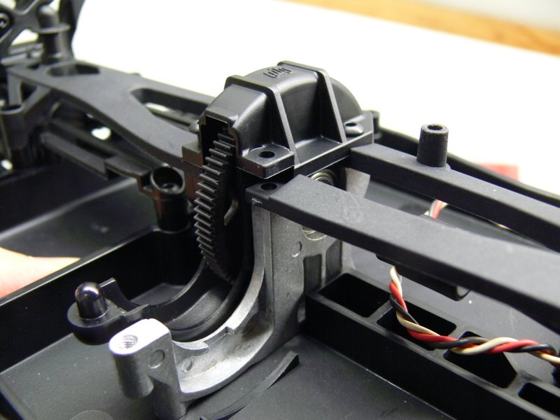
The buggy now has an enclosed spur gear cover, top deck, shock towers
and steering rack. Unlike the D4, there are no ball bearings in the
steering rack. Plastic spacers are used instead.
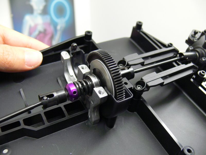
Also did a test fit of a D4 WCE slipper. Happy to confirm it is a drop
in replacement. Looks like the D4 aluminium CVD central drive shafts
from the D4 will also fit if you change the ends of the gearbox.
When building new CVD's, is it normal for them to 'catch' while rotating
by hand? Do they go through a break in period and eventually smooth out?
DAY 3
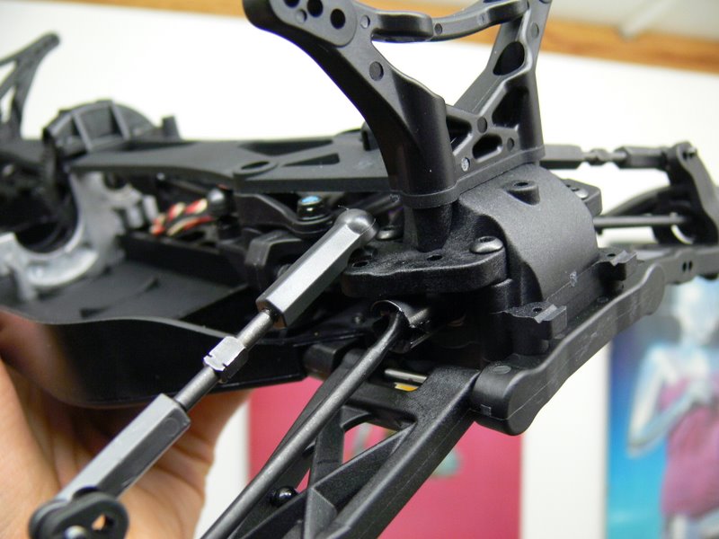
Midnight and my hands are raw from attaching turnbuckles to ball cups.
The turnbuckles themselves are the same thickness as their D4
counterpart, 3mm, but made of steel as opposed to titanium. They are
tastefully black in colour, much like the rest of the chassis.
A nice bonus was the inclusion of 1 degree rear hubs and 13 degree front
hubs. These are in addition to the 0 degree rear and 10 degree front
hubs which the manual suggests to use.
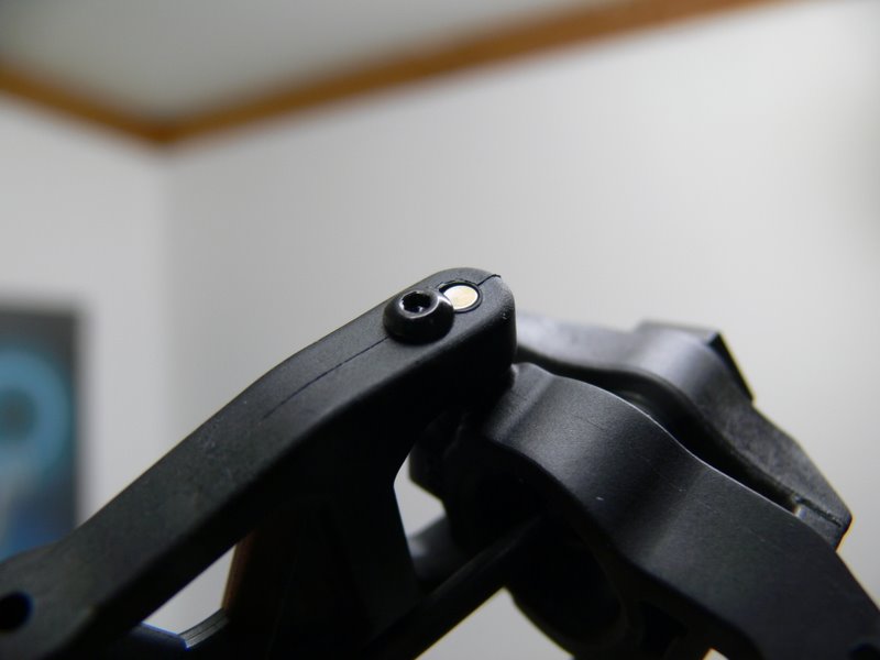
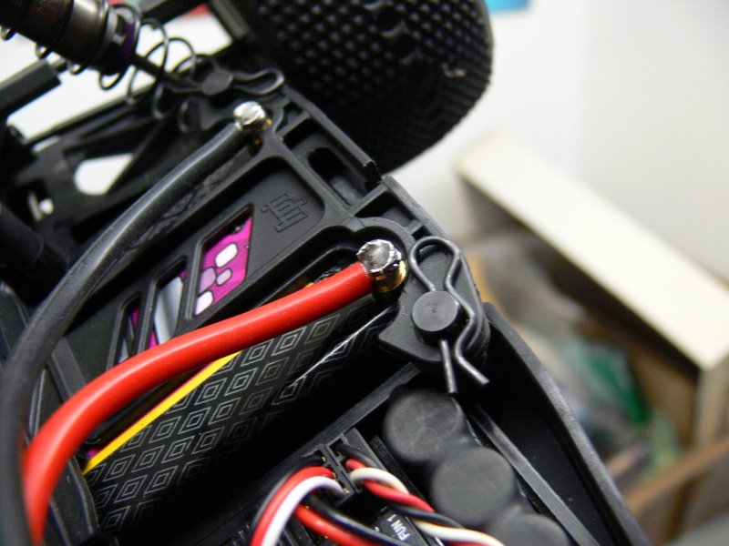
Hub pins are captured with a small screw on either side of the arm with
the top of the screw partially blocking the hole. Personally, I'd feel
more comfortable with a washer in there but it seems to do the job.
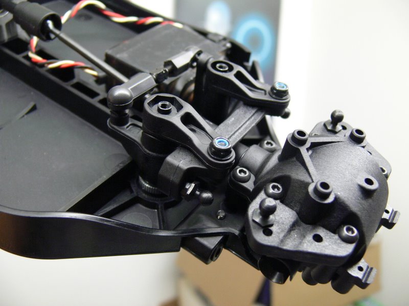
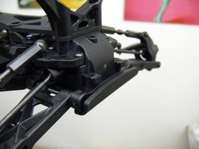
Would have been nice if the front bumper were slightly taller, similar
to the D4 WCE (which is not a direct fit to the Cyber 10b). There are
two points on the gearbox it could push against which I think would
better distribute the force of an impact a little better.
Tomorrow should be a productive day being the start of the weekend. High
on the agenda is to hunt down 'rubber cement'. I'm getting paranoid of
pins flying in all directions. If I can find some CVD rebuild kits
locally, might also have a stab at installing the D4 central drive
shafts along with the WCE slipper.
DAY 4
Completed the chassis this afternoon. I did cheat and used some metal
shocks from the D4. The Cyber shocks are indeed plastic replicas, right
down to the eyelets. The only noticeable different is the use of e-clips
to hold the piston as opposed to a small screw.
While I can understand the use of plastic shocks in an entry-level kit,
using plastic nuts to hold the shocks to the tower is disappointing.
They take the brunt of the impact when you land the car upside down and
I can imagine them quickly grinding away.
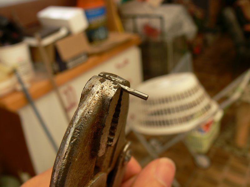
Now it's time for some upgrades. I dremelled a small pit in the CVD pins
as per the instructions
here in a bid to stop the pins from flying out. Also swapped the
stock rear dogbones for some D4 CVDs.
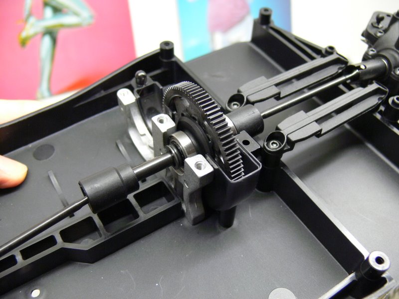
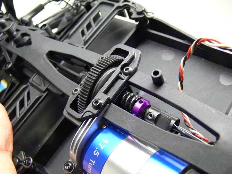
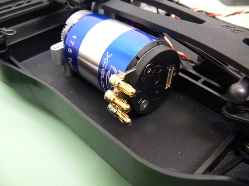
I intend to race in 4wd stock so changed the spur to 80t. Powering the
car is a Losi Xcelorin 17.5 which I have been very happy with in 2wd
stock. I also added in a D4 WCE slipper which is an easy drop in
replacement. After much though, I removed the enclosed gear cover and
opted to leave everything exposed for easier inspection. I found the
inspection hatch to difficult to open and close. Since the car will only
be used on the track, I figured debris would not be a large issue for
me.
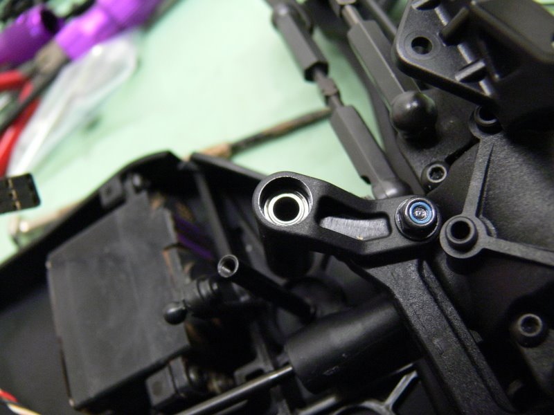
Finally added 4x ball bearings to the steering rack, replacing the stock
plastic bushings. To be honest, it doesn't feel any different. I think
everything is still a little stiff because it's new.
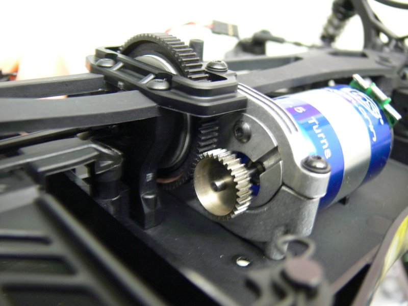
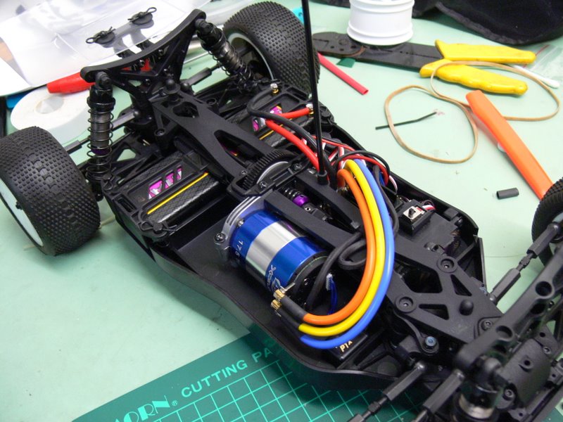
The motor mount mechanism is simply brilliant. The motor sits inside a
bracket which swivels to adjust the distance between the pinion and the
spur. All you need to do is loosen a screw to get very fine and accurate
motor distance adjustment. Once you're happy, simply tighten the screw.
No need to remove battery posts or poke a long hex driver from the back
of the car.
Next step is to cut out the body and plan the electronics layout.
I must admit I might be
wrong about the shock nuts. At the club day yesterday, I noticed all the
FT B44's used plastic nuts. The theory goes that if the shock tower
breaks, the nuts strip right off, minimising damage to the shocks.
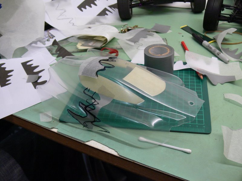
DAY 5
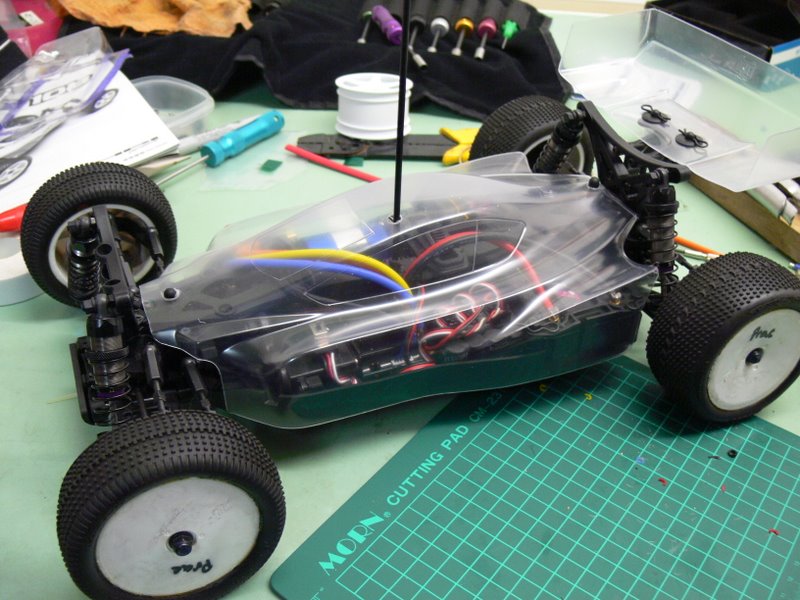
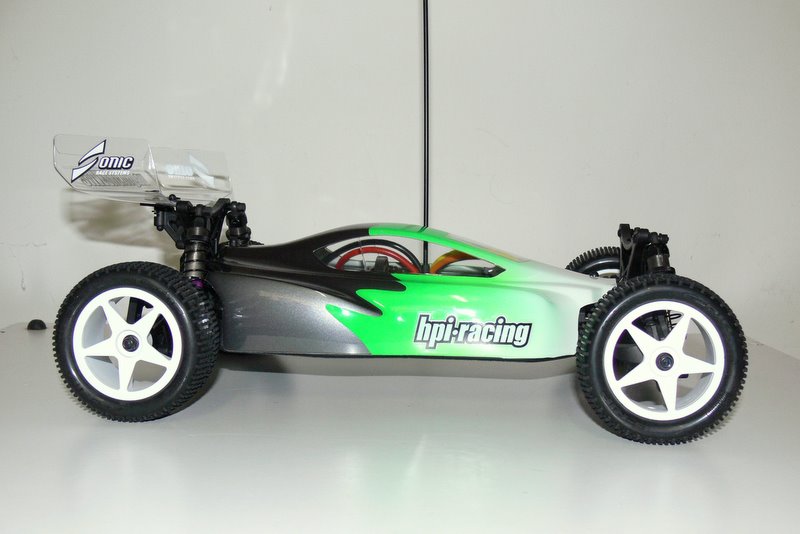
Cut out of the body and wing on Sunday night while watching Eurovision.
HPI must have intentionally designed the body to be easy and straight
forward for a beginner to cut out. Lots of straight lines with all
corners long and smooth. There are no tricky tight corners at all to
worry about.
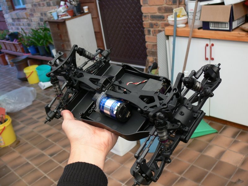
With the body now fitted, I've started planning the layout of the
electronics. Compared to the D4, the chassis is roomy which is not
surprising. The cyber 10b chassis is wider and requires less space for
the battery because most of it is under the shaft. I think fitting a
motor heatsink is going to be a challenge. The body kind of wraps around
the motor leaving little room.
My receiver is too tall to fit in front of the motor (it interferes with
the steering rack) so it looks like it'll be position either behind the
servo or behind the lipo.
I have always liked to have a completely detachable motor and
traditionall used deans plugs. Trying something different this time
round and soldering 3.5mm bullet connectors directly to the motor's
solder tabs.
DAY 6
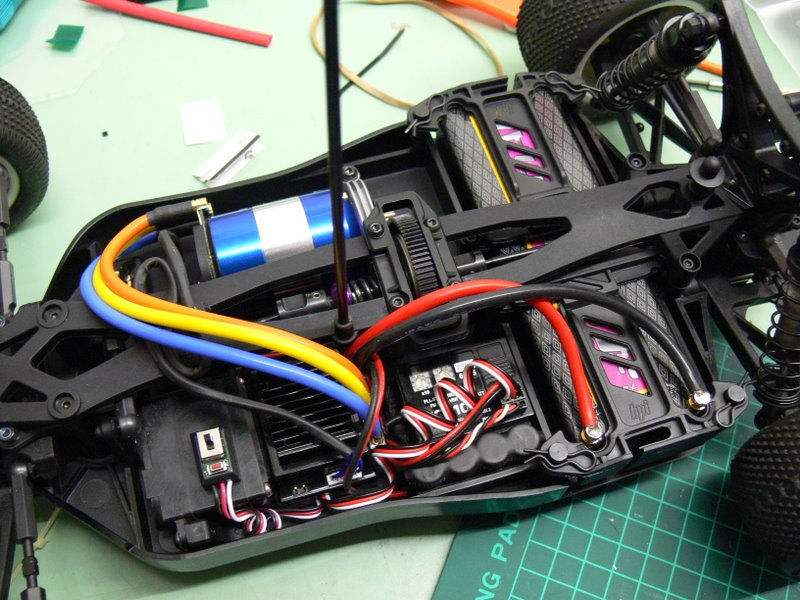
It's alive
Electronics are now in place. Kitted out with a Hobbywing Xerun v2.0, JR
RS-310 receiver, KO-Propo digital FET servo, Intellect IP3800 25C lipo,
MRT transponder and Losi Xcelorin 17.5t motor.
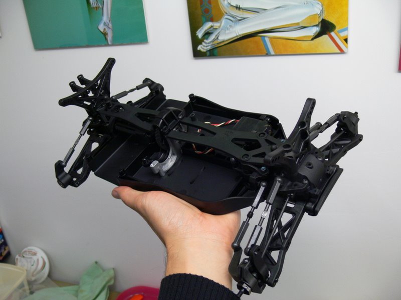
Chassis is indeed very roomy. Spent most of the evening trying out
different ways to route the cables and position the components. Decided
on bringing the ESC up front directly behind the servo to balance out
the weight of the motor.
I did try to position the receiver in front of the motor (B44 style) but
it interfered with the steering rack.
Now comes the fun part - designing a new paint scheme. Meanwhile, I'm
going driving.
DAY 7
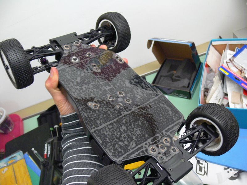
Just some minor stuff today. Applied some JConcept chassis protector
(it's actually just 2 sheets of 3M PFTE adhesive plastic). Never used
the the stuff before, not sure if it's worth the effort to protect a
plastic chassis.
Also had to push the battery forward to stop it from touching the rear
gearbox shaft outdrive. I used some furniture adhesive feet to fill the
space. This in turn caused the battery holder to interfere with the
battery terminals. Only solution was to shave a bit off. End result is
the battery clears the outdrive by around 1-2mm.
Also managed to put the car on the kitchen scales. 1680g all up,
including Intellect 3800 lipo.

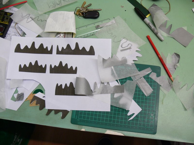
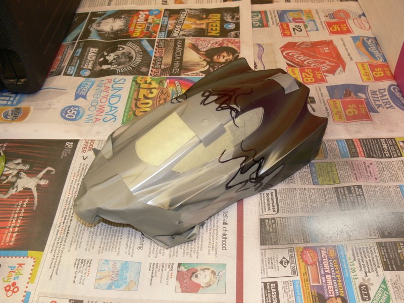
DAYS 8 & 9
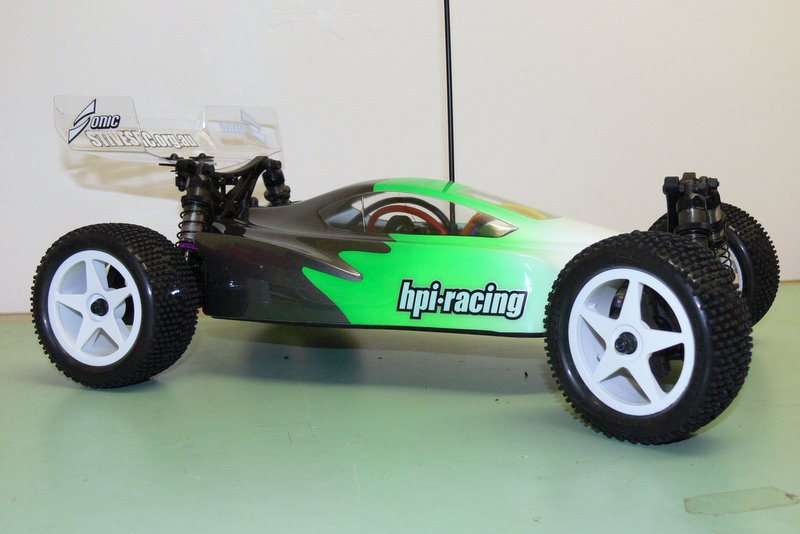
Attached tyres and spent the weekend painting.
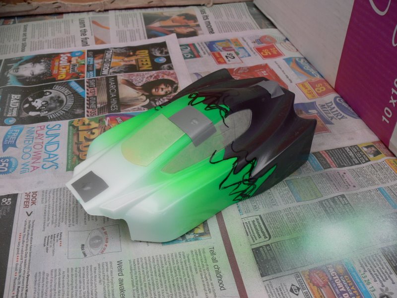

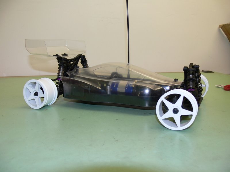
DAY 10
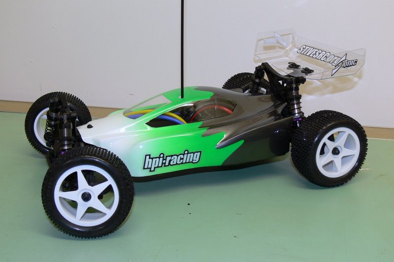
Attached a few stickers and peeled off the paint mask.
That's about it. All in all a very satisfying experience. Only thing
left is to take it to the track and see how it runs. Have to wait for
the weather to clear up a bit before that happens.
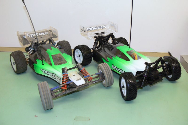
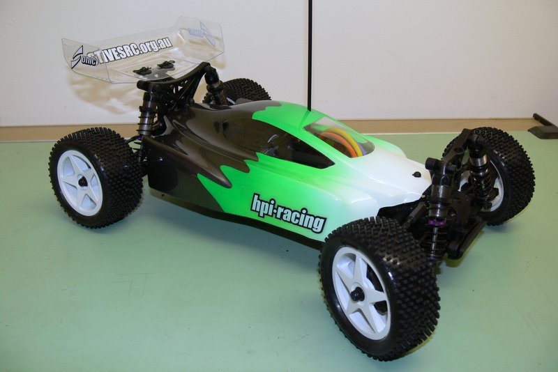
My Cyber-10B finally had its
maiden run today and subsequently doesn't look as shiny as it used to.
Verdict? Easier to drive than a 2wd being my first 4wd, I don't have a
lot to compare it with. The shock towers are tougher than I previously
gave credit for. The car landed on it's lid plenty enough times to prove
that.
The antenna has a rather large kink in it now, I imagine it'll snap
after a couple more upside down landings.
After chatting with some of the more experienced stock drivers, think I
might go back to the non-slipper arrangement. Save a bit of weight and
reduce the rotational mass. |