|
Xpress Execute XQ3S Build Review by Johannes Weber
Johannes is back at it again with a super in-depth review of our recently released sports touring car: the Execute XQ3S! Here's what he had to say:
With the XQ3S, Xpress is bringing the expected sports variant of the XQ11 touring car released last year onto the market. The XQ3S inherits many features from its bigger brother, but allows for a significantly lower price thanks to a different choice of materials. Instead of carbon fiber and aluminum, fiberglass and plastic are used.
The XQ3S can be seen as the successor to the XQ2S. It comes with many features that had to be retrofitted as tuning parts on the XQ2S. Above all, it is no longer necessary to buy a mid-engine conversion kit, as the XQ3S has a mid-engine layout straight from the kit. Retrofitting aluminum wheel hexes are no longer necessary. Only double-joint CVDs on the front axle and stabilizers are not part of the kit.
WHAT'S NEW?
Apart from details, the XQ3S differs from the XQ11 mainly in the choice of materials and the design of parts, which in the the bulkheads on the XQ3S are once again made in one piece. Nevertheless, shock towers were dispensed with and a plastic version of the LCG conversion kit was integrated.
Compared to the XQ2S, the entire chassis geometry has changed with the narrower bulkheads and longer swing arms. It is largely identical to the XQ11 and represents the current state in 1:10 touring cars.
The rest of the differences will be discussed in the description of the structure.
CONSTRUCTION
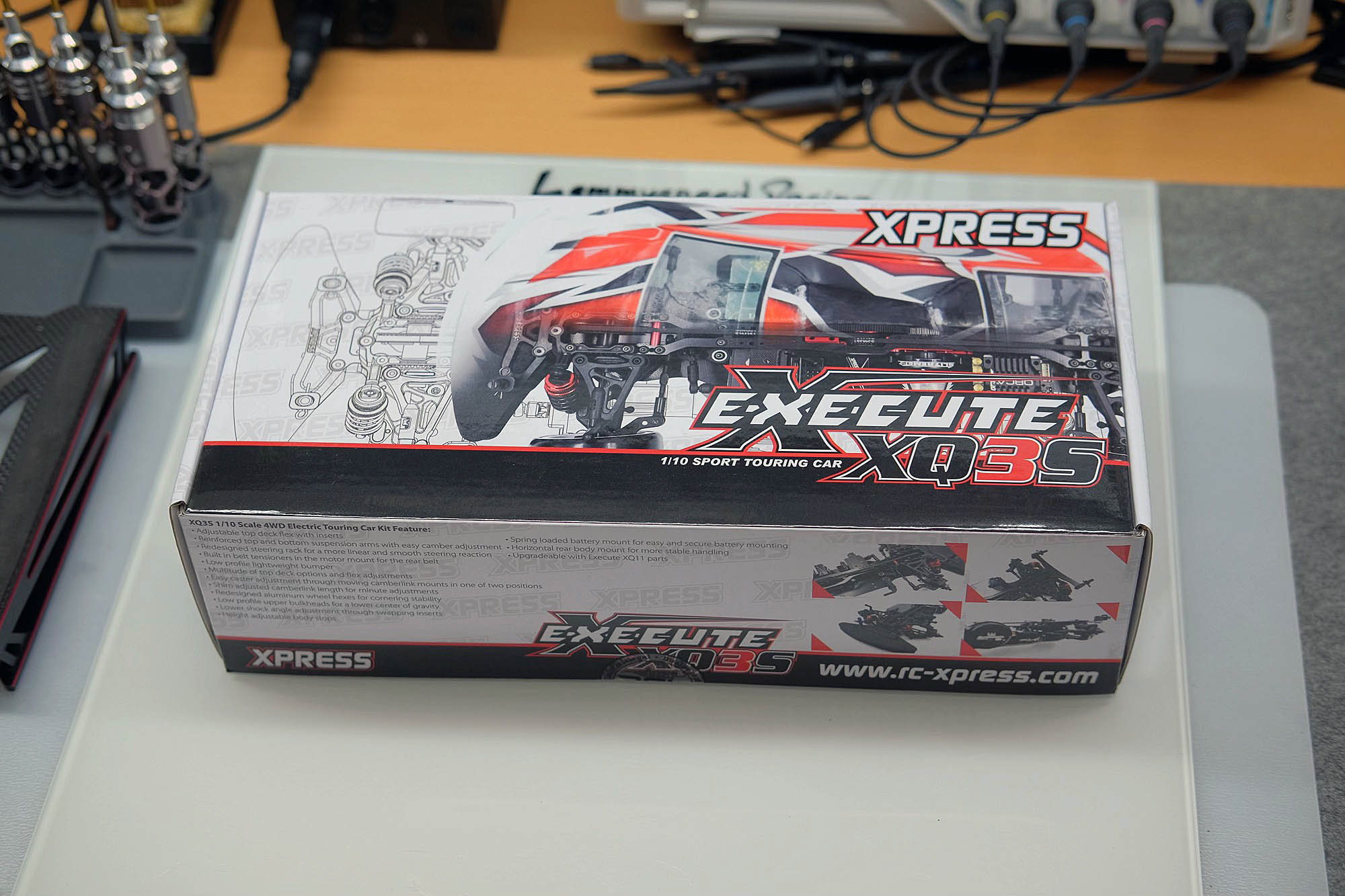
When you open the box you don't expect anything new or unusual. There are printed instructions included and all construction sections are sealed in plastic bags. This avoids too much confusion during construction. The instructions contain a few corrections that contain additional information or correct things that were incorrectly presented. However, when building the rear body mounts, you realize that even the corrected version of the instructions does not match the contents of the kit. A small solvable problem.
SUSPENSION
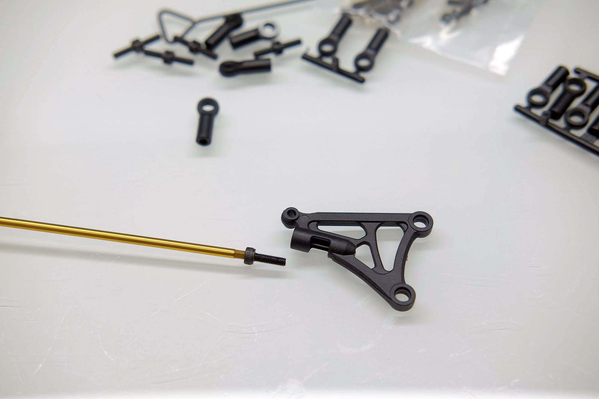
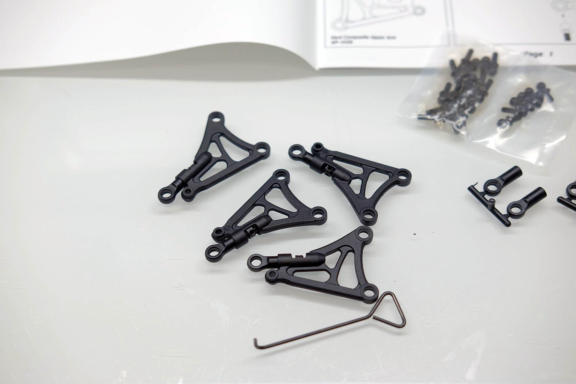
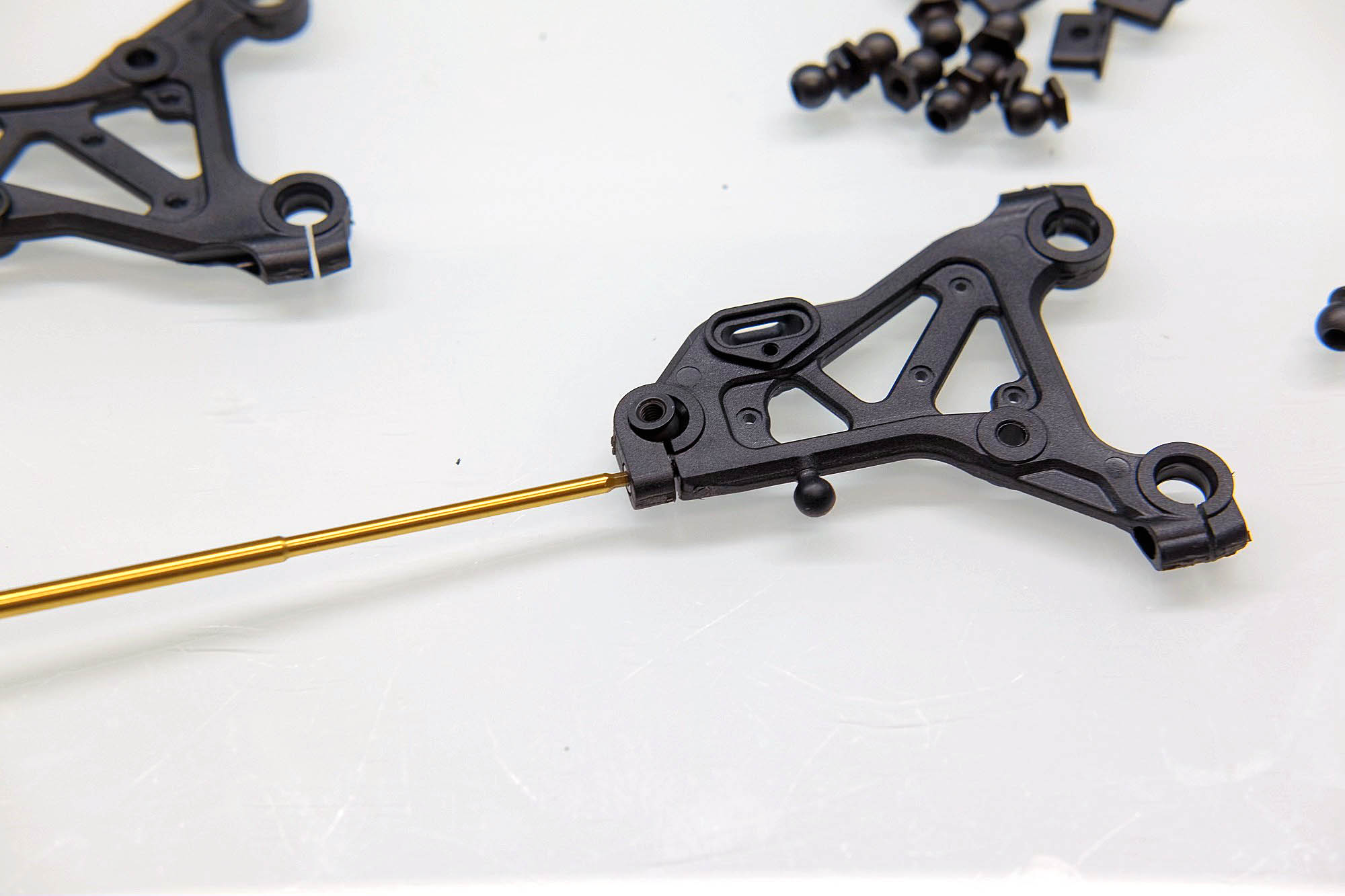
Construction starts as usual with the suspension arms. First the upper wishbones are built, they thread into which the threaded rods are then screwed is first pre-cut with the included screw. After screwing on the ball sockets, the threaded rods are screwed into the wishbones. Pre-cutting is absolutely necessary, otherwise not enough force can be used to screw the threaded rods into the wishbones.
It is important to ensure that the length described in the instructions is correct and that there are approximately the same number of threads on the left and right so that adjustment can be made later during use without any problems.
When building the tie rods, there is nothing unusual to consider other than the length of the ball heads used.
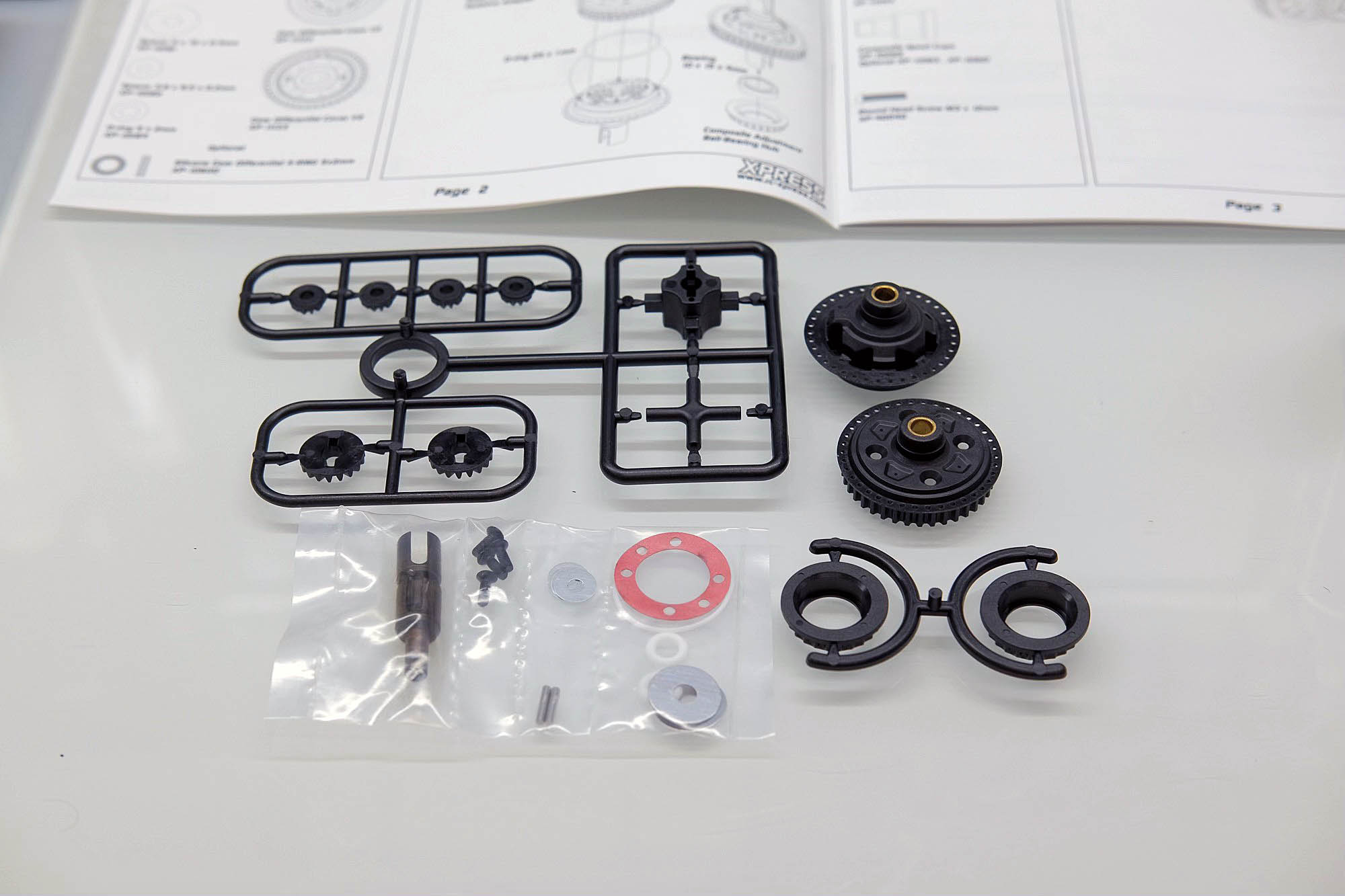
DIFFERENTIAL
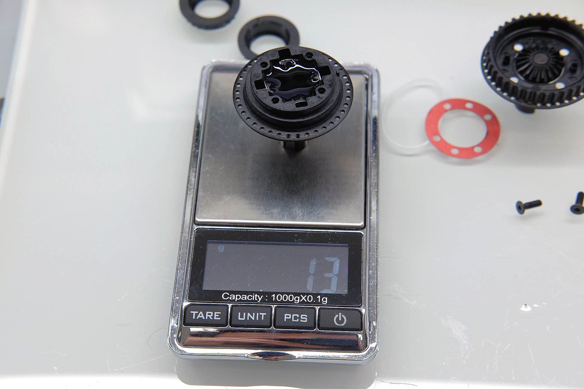
The differential is then built. It's not just the width that has changed compared to its predecessor. Brass bushings were pressed into the housing halves, which ensure that the drives run better. The rest is unchanged. The O-rings should be lubricated with damper oil and 1.3g of oil should be poured into the differential. I chose asphalt for 5k oil as a starting value. On carpet you may want to start with 7k depending on the grip of the track. The weight information is used to ensure that the differential is not overfilled and ensures that, even when the oil is changed, there is exactly as much oil in it as before. When removing the bevel gears from the sprue, you should not only make sure that there are no burrs left, but also that there are no plastic residues stuck in the teeth. These can quickly lead to premature death of the differential. The pin in the deeper half of the housing is best inserted with needle-nose pliers.
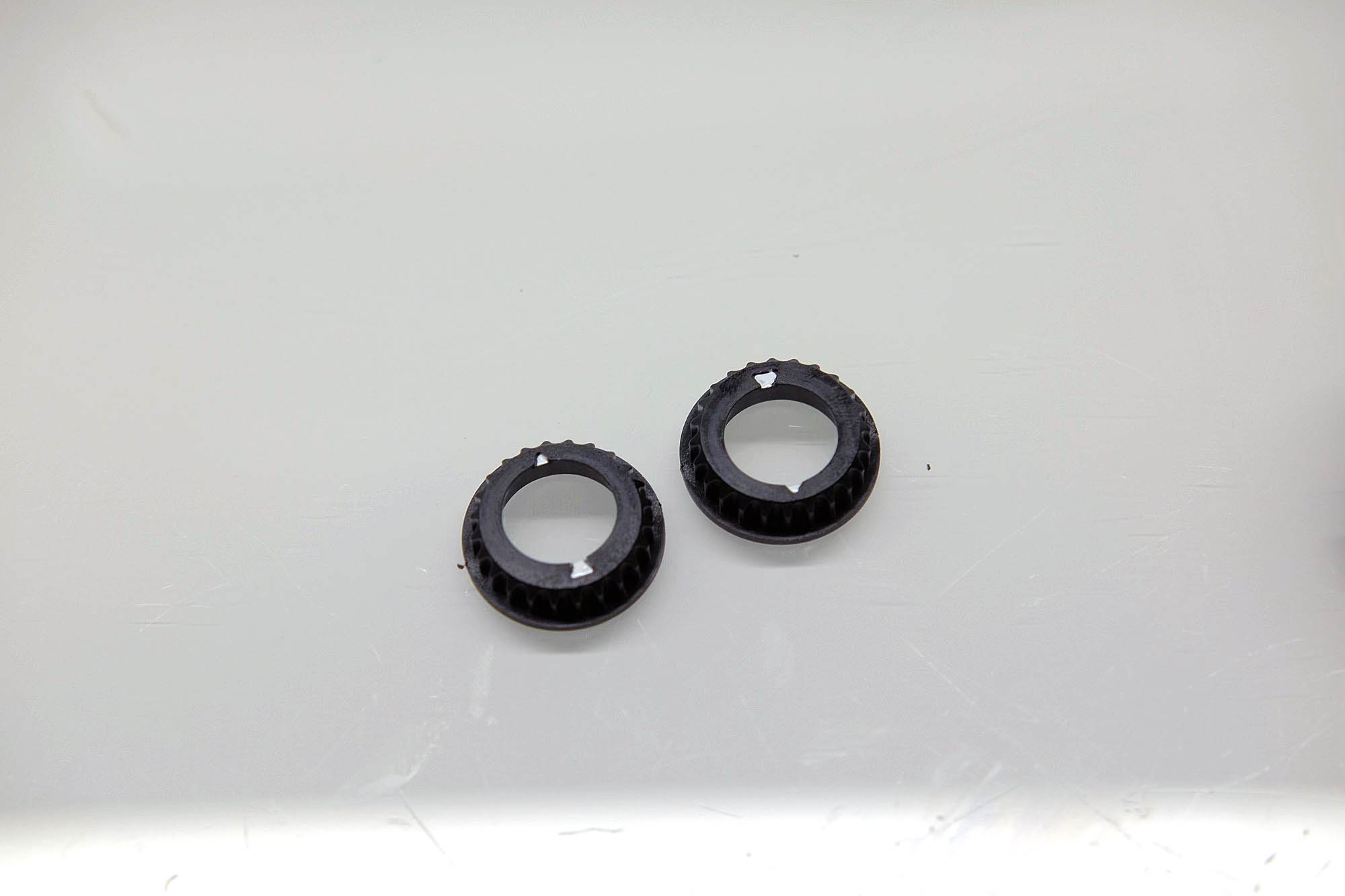
I marked the eccentrics of the ball bearings with white markings. This makes it easier to see their orientation when installed, even if the lighting conditions are not optimal. A touch-up pen is best suited for this.
LOWER CONTROL ARM
After the differential, the lower swing arms are built, which are now significantly more complex than on the XQ2S. In addition to the mid-engine layout, they are one of the biggest innovations on the XQ3S. They are not only longer, but also have a completely different design than before. After separating the sprue residue, the balls are pressed in. It is important to ensure that the balls with a hexagonal collar come to the inside of the swing arms. It is also important to ensure that the swing arms are correctly aligned before pressing them in. The screws are then applied to ensure adjustable swing play. The screws should be tightened to such an extent that the balls have almost no play left, but do not jam either. The line between too loose and too tight is very thin here, but proper adjustment is absolutely necessary!
This setting should be checked regularly. It can be assumed that the balls will gradually gain some play so that adjustments should be made every now and then.
As with the XQ11, the damper is attached to the swingarms via inserts in the wishbones, with which the position of the attachment can be changed. It is important to ensure that the set screw is not screwed in too deeply. Otherwise it will hit the swing arm itself at the end of the hole and the thread of the insert will come out. If necessary, plates can be screwed into the wishbones, which are again available in two degrees of hardness, which additionally stiffen the swing arm. This is particularly advantageous for routes with a lot of grip, i.e. usually on permanent indoor routes with carpeted surfaces.
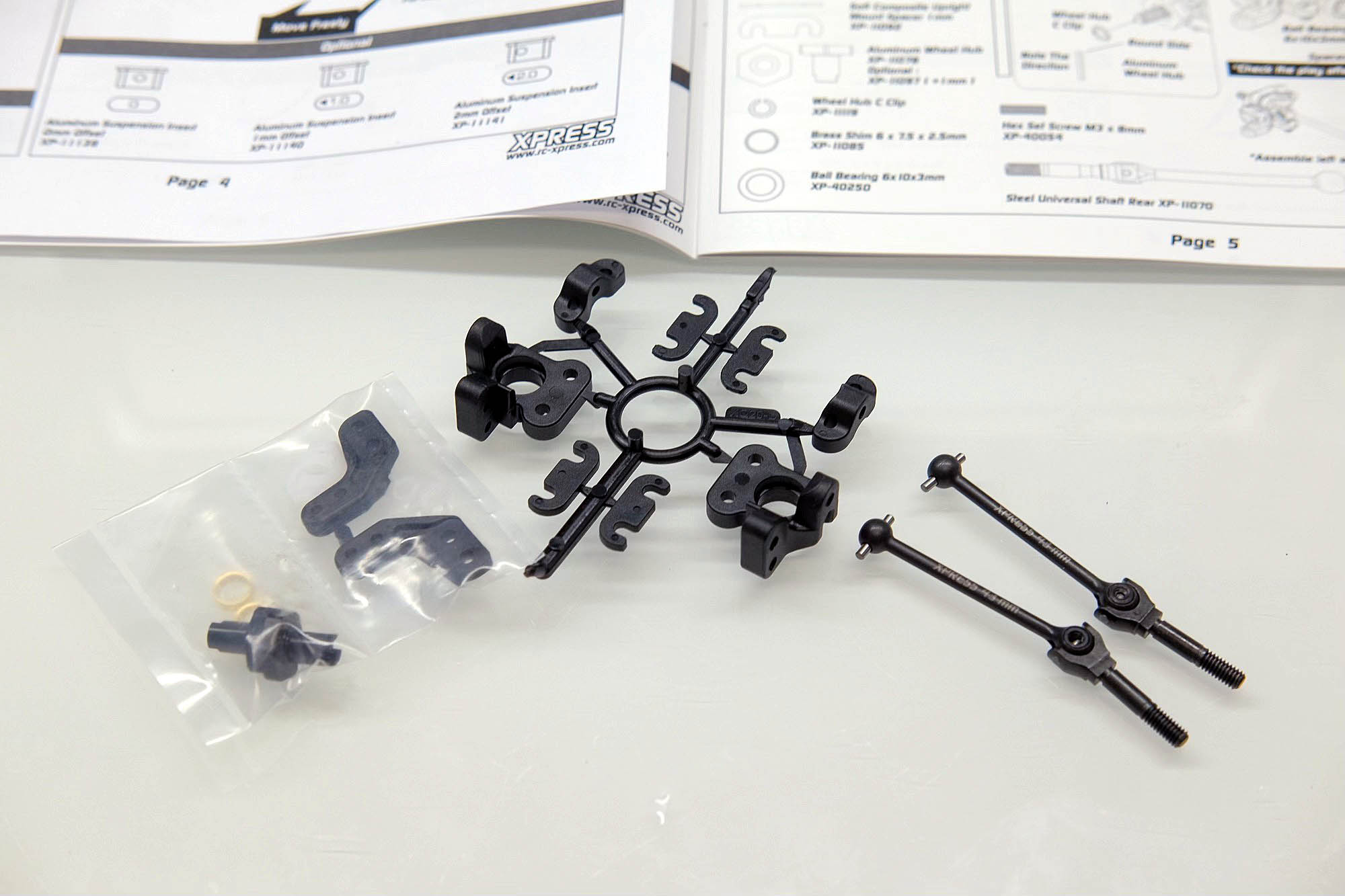
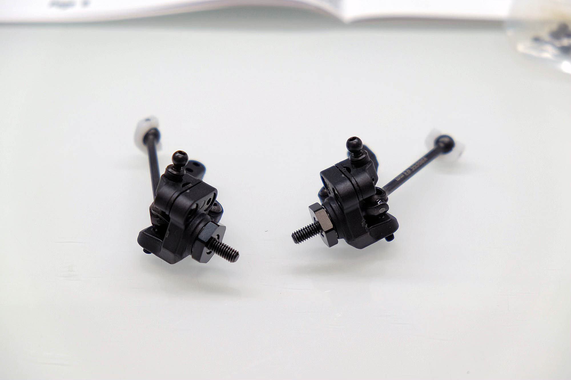
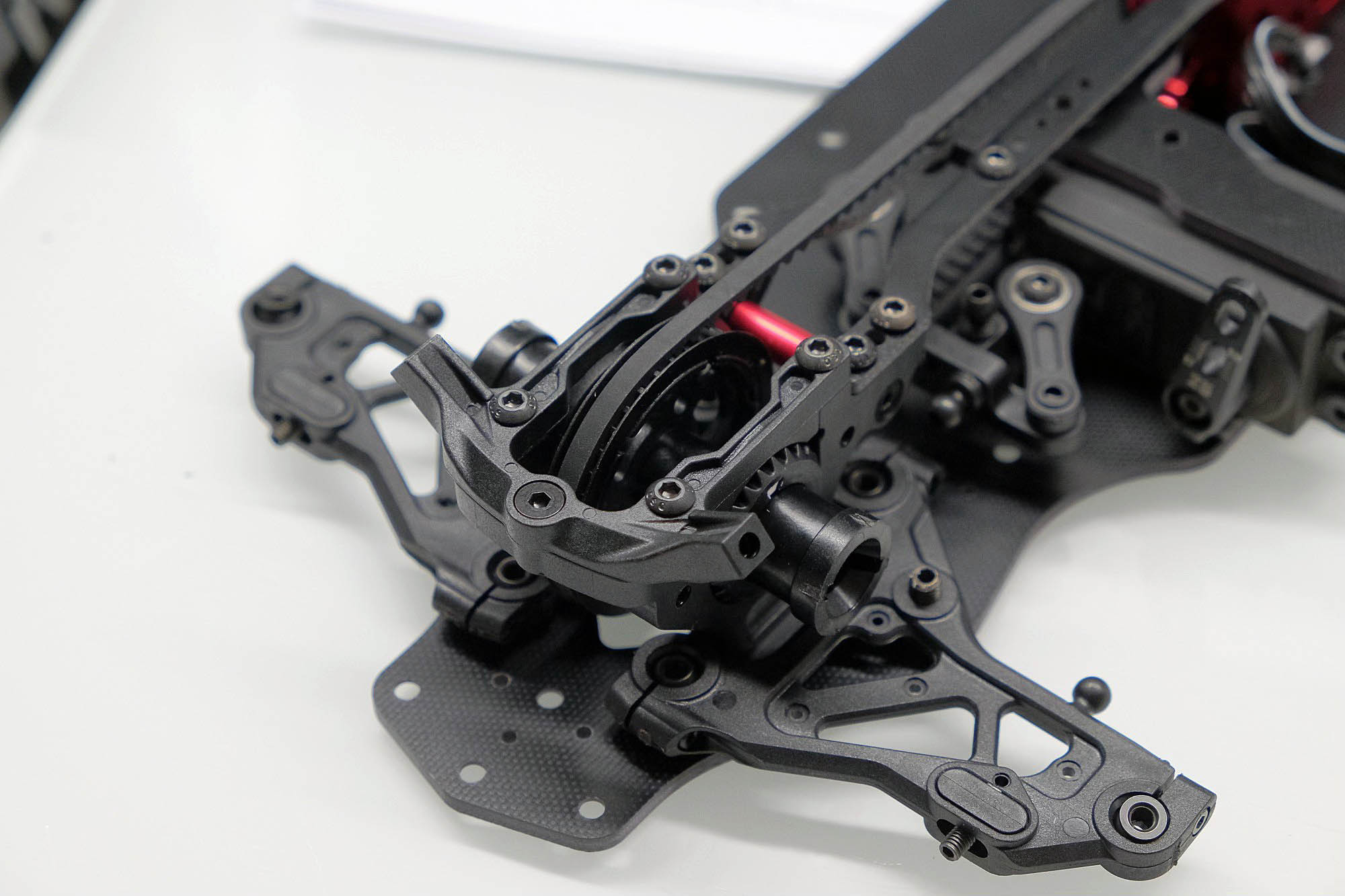
STEERING LEVER / WHEEL HUBS
The front and rear steering levers or wheel carriers are a completely newly designed part compared to the the upper wishbones prevent the
vehicle from tipping over and take over the holding function that was previously implemented via the pin in the lower wishbone. Among other things,
the caster angle can now be adjusted continuously, but more on that later.
What has remained the same as its predecessor is the screwing on of the arm to which the steering linkage or tie rods will later be attached.
The upper attachment point is fixed to the steering lever with two screws. The position of the ball head can be moved further towards the chassis using spacers.
The wheel driver was also changed. Instead of the previous solution with a pin in the wheel axle, the driver is now pushed completely over the axle and secured with a plastic ring. Be sure to pay attention to the orientation when pushing the ring on. This has a flattened side. This must definitely be installed in the direction of the wheel driver. The new design also means that the dimensions of the ball bearings have been changed. Identical ball bearings measuring 6x10x3mm are installed in all positions in the wheel carriers.
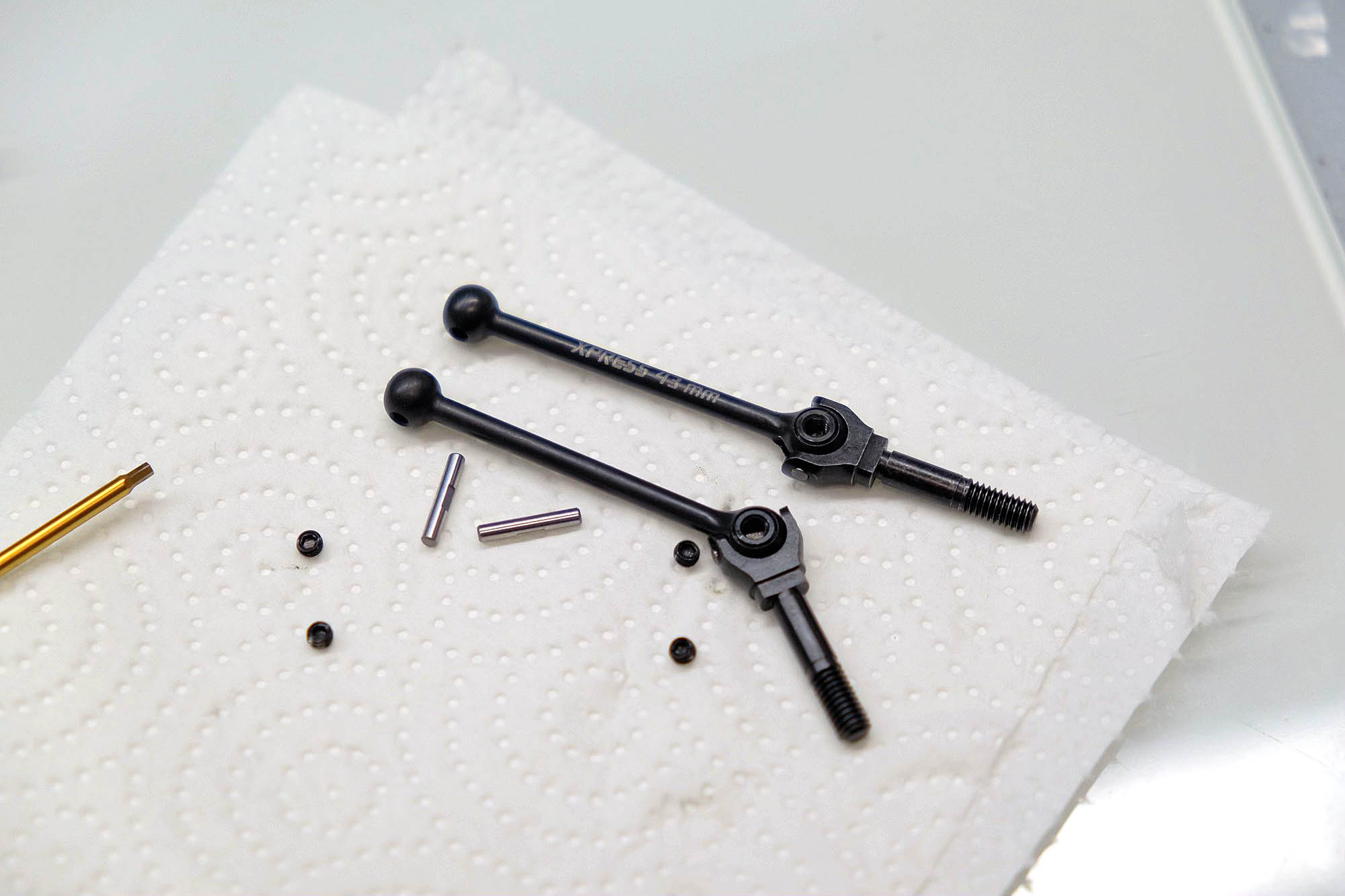
The CVDs have also been slimmed down and their design has been changed. Although they come out of the bag apparently fully assembled, they have to be disassembled again, cleaned of oil and grease and reassembled. During this process, the blades can be installed directly on the rear axle. Unlike the CVDs on the XQ2S, the pins that hold the blade can be removed. This eliminates the tedious installation process where the blade has to be strangled over the pin. When screwing together, it is important to pay attention to the flattening of the pin. This serves to give the grub screw a reasonable contact surface and prevents the pin from twisting. The pin, which is then inserted into the spool outputs, should be perfectly centered, especially on the front axle. If one side protrudes further than the other, this will cause the spool exit to get caught, causing the suspension to get stuck and not function properly.
Cleaning the CVD parts is necessary so that the screw locking varnish, which must be used, holds properly and the screw connection
effectively prevents the pin from wandering. There is a lot of potential for damage hidden here if the pen moves and flails around while driving. Please
only use medium-strength Loctite as screw locking varnish. Finally, each CVD must be greased or oiled again. CVDs running dry are quickly damaged.
As described in the instructions, the fit between wheel axle – wheel carrier – ball bearing must be shimmed correctly. A sufficient quantity
of the appropriate shim washers are included in the kit. The axle should no longer have any play with the installed wheel driver, but should not jam
either. If in doubt, it is better to use one less disc and check again after the first ride.
The rear wheel carriers are constructed according to the same principle as the front steering levers. The rear CVDs also had to be slimmed down and lost material. Here too, it is important to take care to disassemble the CVDs again, clean them and secure the grub screws with screw locking varnish.
As with the XQ2S, the kit does not include double-joint CVDs for the front axle. These can be retrofitted to the XQ11 as a tuning part and are still highly recommended. You don't notice the difference so much on outdoor tracks due to the larger curve radius, but on narrow indoor routes the normal CVDs tend to hit and slow down the vehicle unnecessarily.
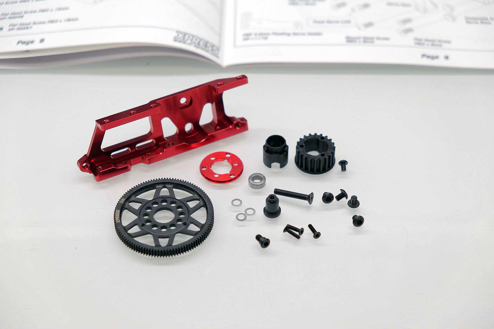
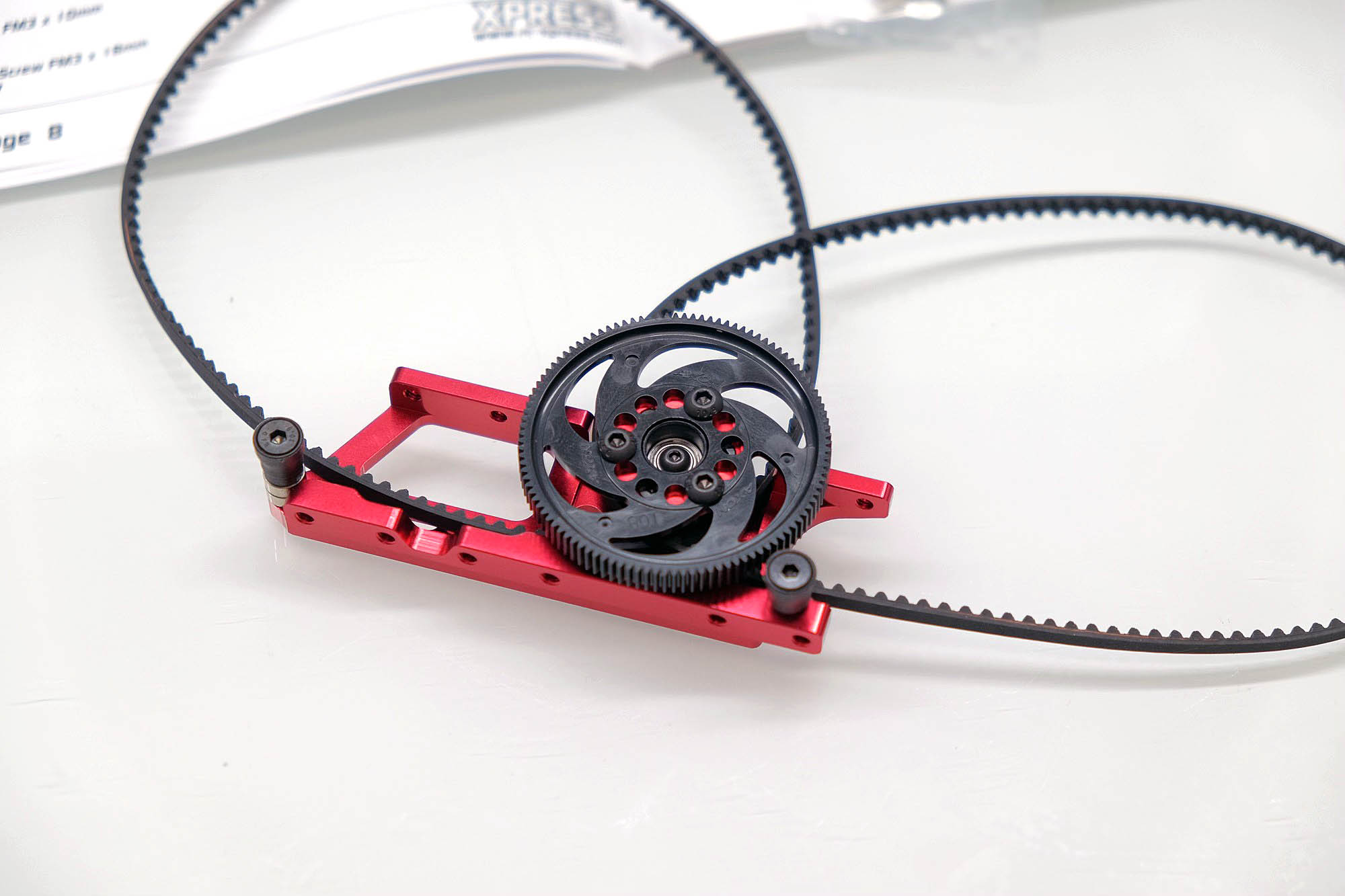
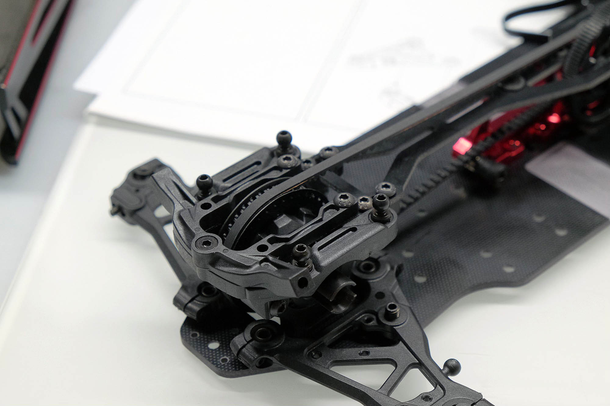
CENTER SHAFT / MOTOR MOUNT
Due to the narrower distance between the bulkheads, not only the diff and rigid axle have become narrower. The center shaft and pulleys have also been significantly changed compared to the mid-engine kit from the XQ2S. Instead of running on both sides of the main gear as before, both belts now run on one side. This results in a new, wider belt wheel. Unlike the XQ11, where the main gear is held with a union nut, it is still screwed on the XQ3S. The screw connection with the aluminum ring, which itself is screwed back to the belt wheel, is a good and, above all, durable solution - even if the main gear is changed more frequently.
As with the CVDs in the wheel carriers, shimming may also be necessary for the medium shaft. Some play is necessary, but not too much or too little.
Although this is explicitly pointed out in the construction instructions, be sure to use loctite when attaching the center shaft to the motor holder! Vibrations occur here due to the motor and the forces during braking and acceleration processes, which can loosen the fastening over time.
A popular topic with the XQ2S is forgetting or omitting the stops for the lipo. These should both be built according to instructions and used as such. If this does not happen, the lipo will touch the main gear.
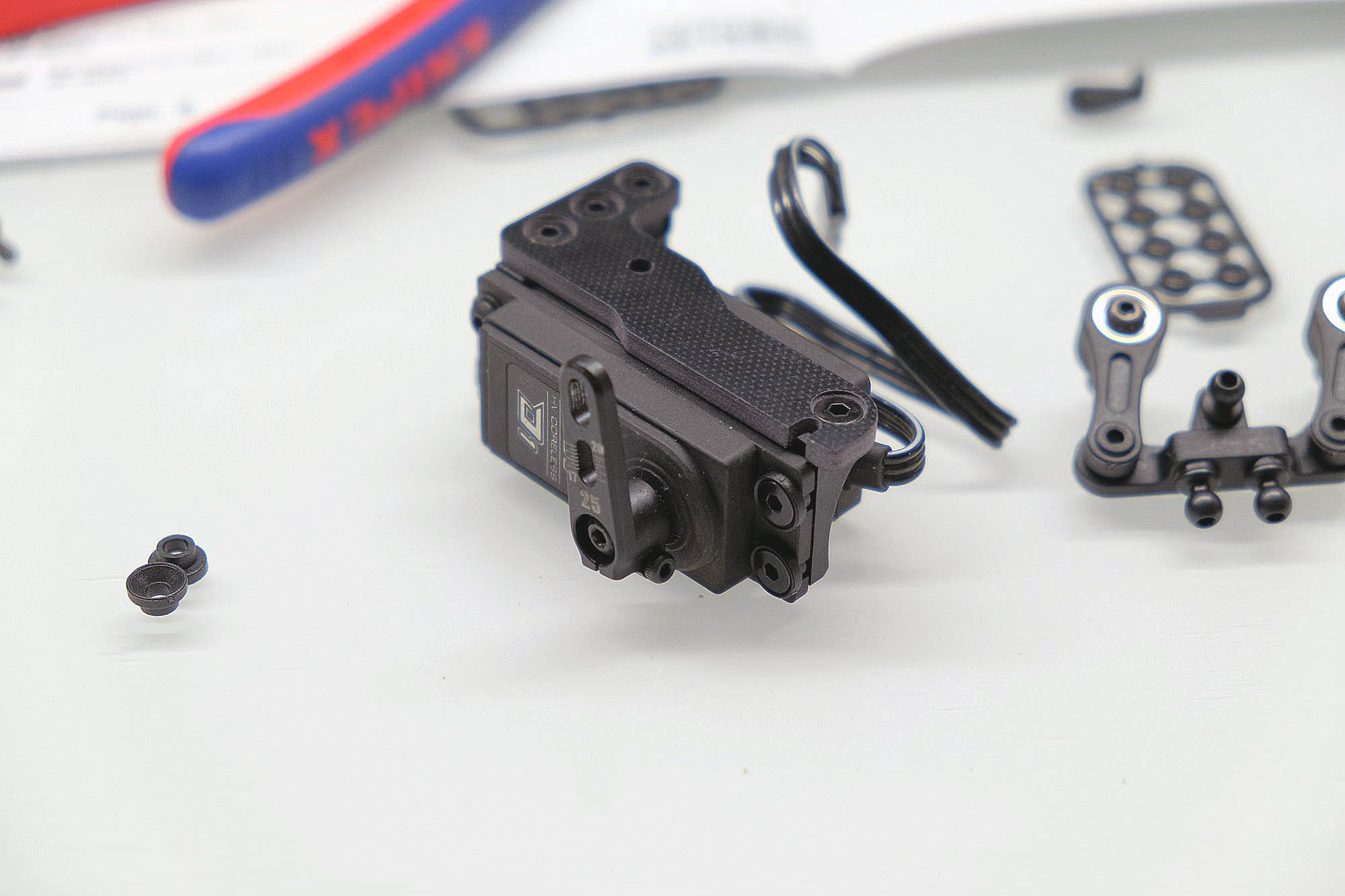
STEERING / SERVO MOUNT
The steering linkage has been moderately revised compared to the XQ2S. The bridge is now screwed to the steering arms from below instead of
from above as before. New screws with a flattened head are also used. These are important at this point because normal pan head screws would rub against the belt when turning.
Another good detailed solution are the servo shims or fasteners made of plastic, which ensure a good hold of the servo without having to tighten the screws too much. Unlike the XQ2S, steel steering posts are now included. These are not only more stable but also ensure that the thread can no longer come out so easily.
As always, servo horns are available in 23 and 25 teeth, so they should fit all common servo manufacturers. If you have confidence in your own driving skills and the quality of the servo you use, you can go straight to an aluminum servo horn. In my opinion, the adjustable length and the directness gained have a positive effect on the driving behaviour.
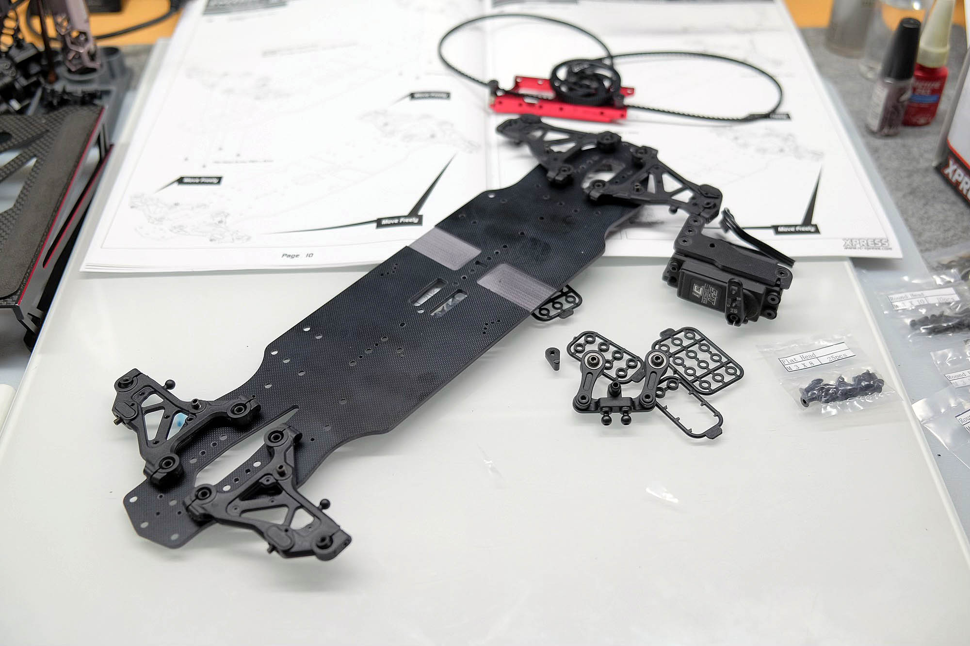
CHASSIS PLATE / ASSEMBLY
The instructions continue with attaching the swingarms to the chassis plate. What the Xpress instructions completely ignore is the processing of the chassis plate before assembly. Everyone has their own approach here. It is difficult to judge right or wrong here. Personally, I usually sand the outer edges of the chassis plate round and then seal the end faces with superglue. However, with the already stiff fiberglass panels, this can have a counterproductive effect on the torsional behavior of the chassis panel.
This time – as with the XQ11 – I decided not to seal the edges with superglue.
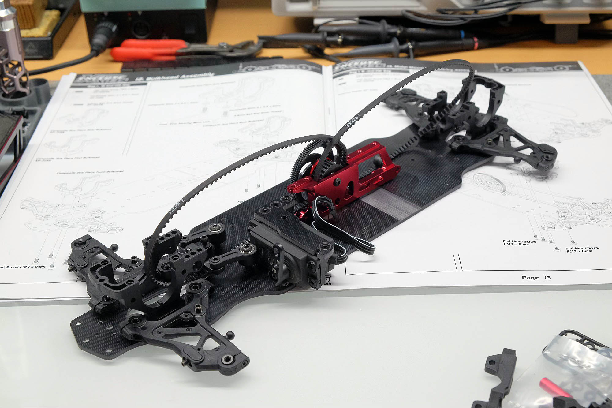
After the swing arms, the lower bulkheads and then the motor mount and servo mount with steering posts are mounted. The top deck is then assembled. Just place the screws here and only tighten them at the very end of the construction process. When installing the differential and rigid axle, the position of the eccentric belt tensioners specified in the instructions works well for me. The straps are sufficiently loose, but still have room to stretch a little without skipping.
The upper bulkheads are available in two versions for the front and rear axle. Make sure that the short ones are installed at the front and the long ones at the back. The difference is clearly visible in the instructions.
The upper wishbones are then clicked onto the wishbone holders. The connection is quite tight, which requires a lot of force when
inserting it for the first time. If you want to use pliers, it's best to use small, adjustable Knippex pliers and place cardboard on top so as not to damage the ball sockets of the wishbones. When attaching the wishbone holders to the bulkheads, you can see how the caster angle can be adjusted on the front and rear axles. Unlike the XQ11, there are no shims on the front or back of the bulkheads. The XQ3S only offers two positions for the caster angle on both the front and rear axles. The standard setup specified in the instructions of 4° caster angle at the front and 2° caster angle at the rear represents a good starting point.
The tie rods are then connected to the steering levers. It is now clear at the latest that the active rear axle is also part of the XQ3S modular package. With its predecessors, the solution mentioned by Xpress OPCS had to be purchased at a higher price. This not only makes it possible to continuously adjust the track on the rear axle and achieve load-dependent track adjustment. A problem that is often ignored is also resolved, which concerns the symmetry of the track on the rear axle. In some (not all) kits across the
XQ10, You noticed that this wasn't just gut feeling or fussiness when you had to clearly re-trim a perfectly tuned chassis with the zero point set on the setup system in one direction so that the straight-line stability was correct.
Thanks to the rear tie rods with the new design, this issue is also a thing of the past.
This completes the rough chassis assembly. The dampers and a few little things are still missing.
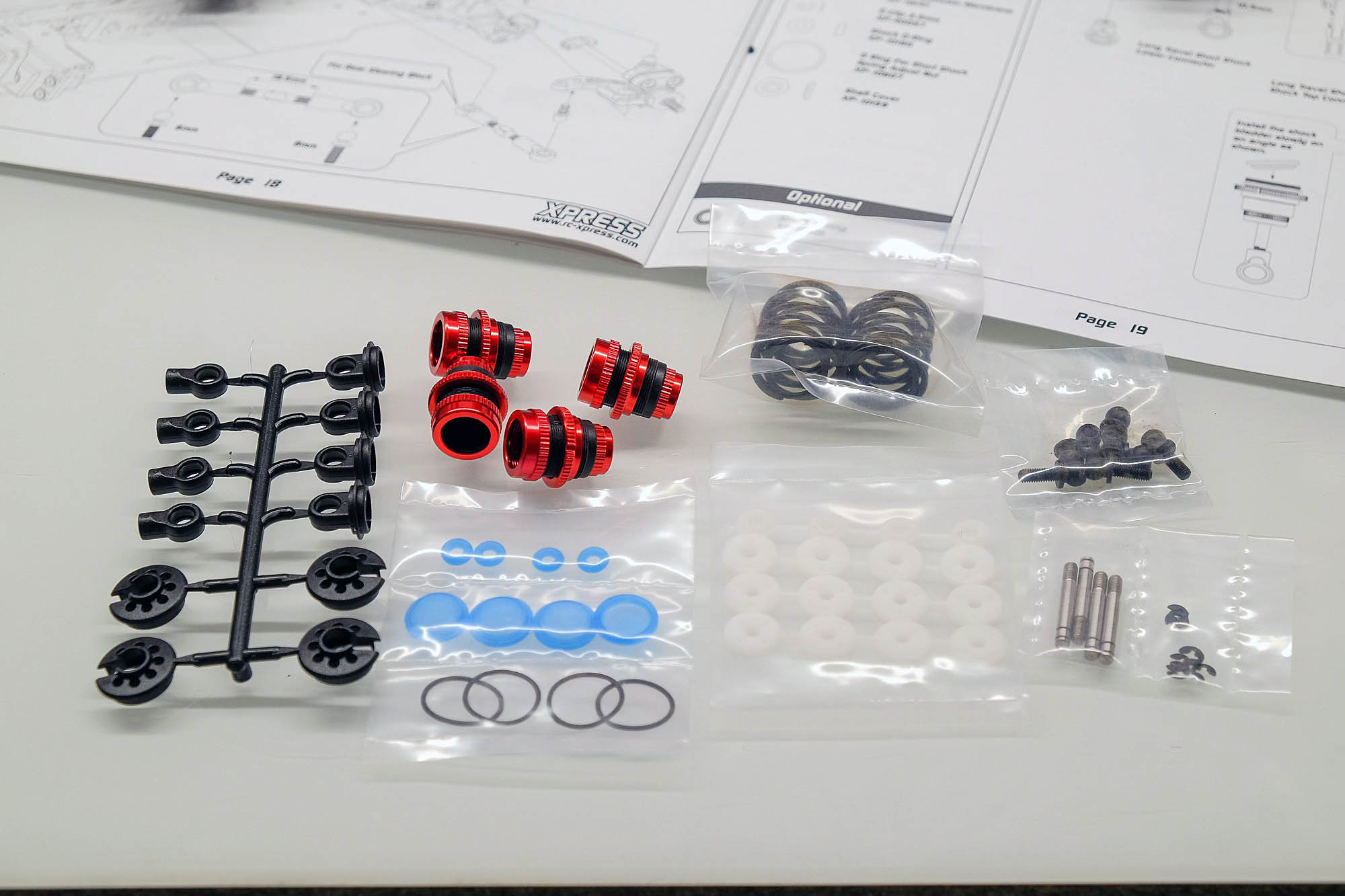
DAMPERS
The Long Travel Short Shocks have itself proven and work well. The process of filling and placing the membrane is well described in the instructions. Good and precise built dampers carry essential to the performance of one vehicle at. Free of air, same length, identical rebound and no play are here important things. A vacuum pump for this absolutely worthwhile - and recommended. When unscrewing the lower one ball socket is exactly on it to pay attention to that in the instructions specified Dimension between Ball socket and lower Damper closure. If this is the case, it gets stuck far twisted Piston rod, the ball socket and the ball head can not work smoothly.
BODY HOLDER
This is where you first come to the point where you realize that something doesn't quite fit given the number and length of the screws available.
There were no M3x12mm screws included in my kit. According to the instructions, these are needed for the first time when attaching the rear body mount bridge.
For this I used the 2x M3x14 screws, which according to the instructions are not used anywhere else. The feeling is that 12mm screws would have been too short at this point - so it fits.
A quick preview of construction phase 23: Here, too, you can see that the missing M3x12 screws are needed to attach the rear body mounts to the bridge. I still had a sufficient number of M3x10mm screws left. So I used that for that. This fits and despite the shorter screws there are enough threads to create a secure connection.
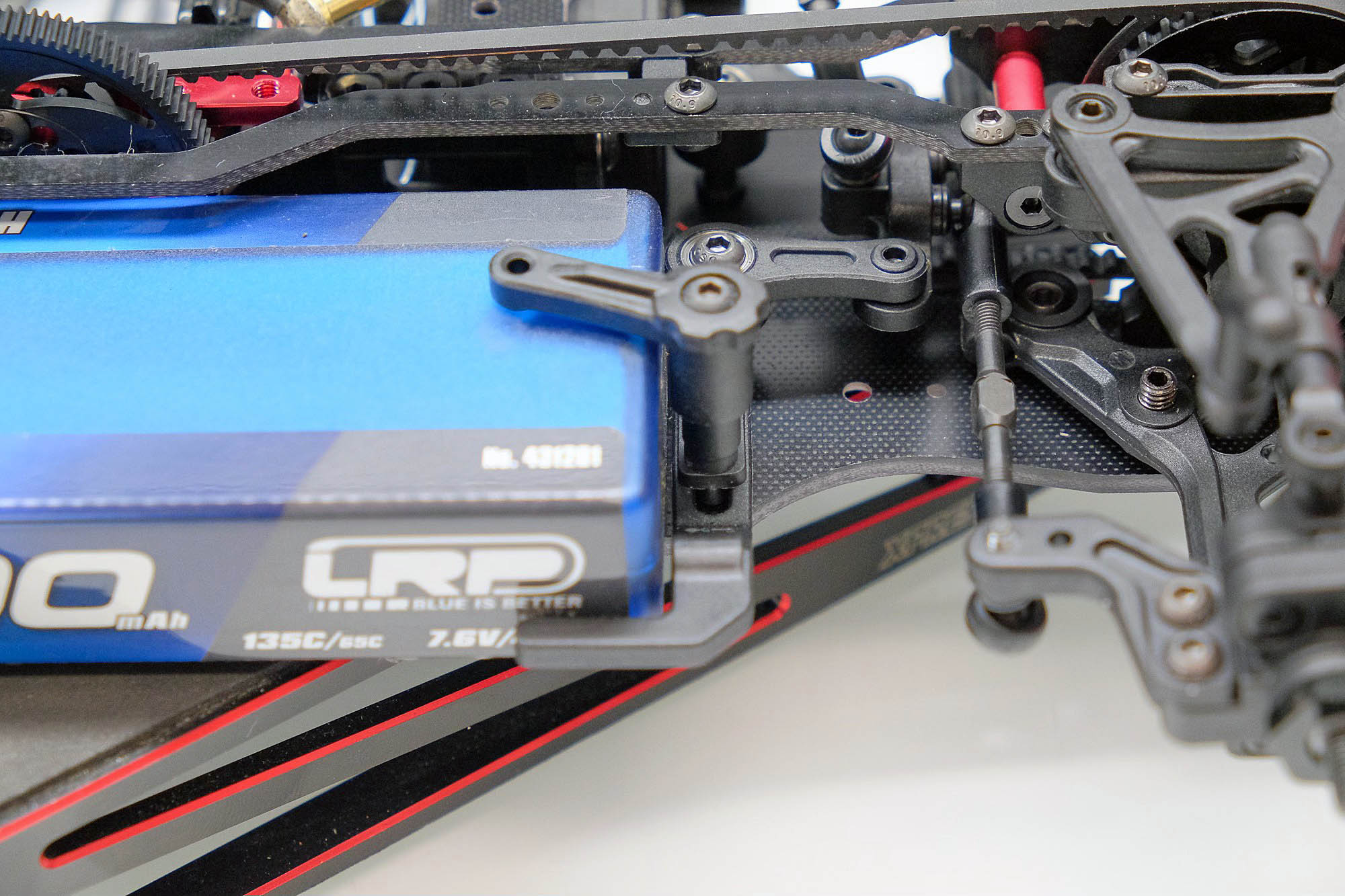
BATTERY MOUNTING
A revised version of the plastic spring holder of the XQ2S serves as the battery holder. The biggest weak point of the old bracket was eliminated at first glance. However, the instructions reinstate the weak point here. Why? The old holder had the problem that the battery on the front only rested on the outside of the holder. In a crash, the leverage reached its full potential and the battery holder broke. Now the battery is in full contact with the front - if, contrary to what is described in the instructions, you leave out the front M3x6 adjusting screw. At least that's what I thought and that's what I did with the XQ11.
However, this is not possible with the XQ3S because the battery then touches the steering arm. In the XQ11 this is made of aluminum and requires less lining around the bearing seat. Here the distance to the lipo is still correct. So you use the screw as intended and risk a very likely break, or use a spacer solution that ensures that the battery rests on the holder over a larger area. I printed a small spacer that also serves as a spacer for the post of the battery holder and is held in place like this.
When adjusting the battery holder, make sure that the battery has minimal play in all directions and is not stuck in the holder. If the chassis twists, the battery must be able to move so as not to negatively influence the twist.
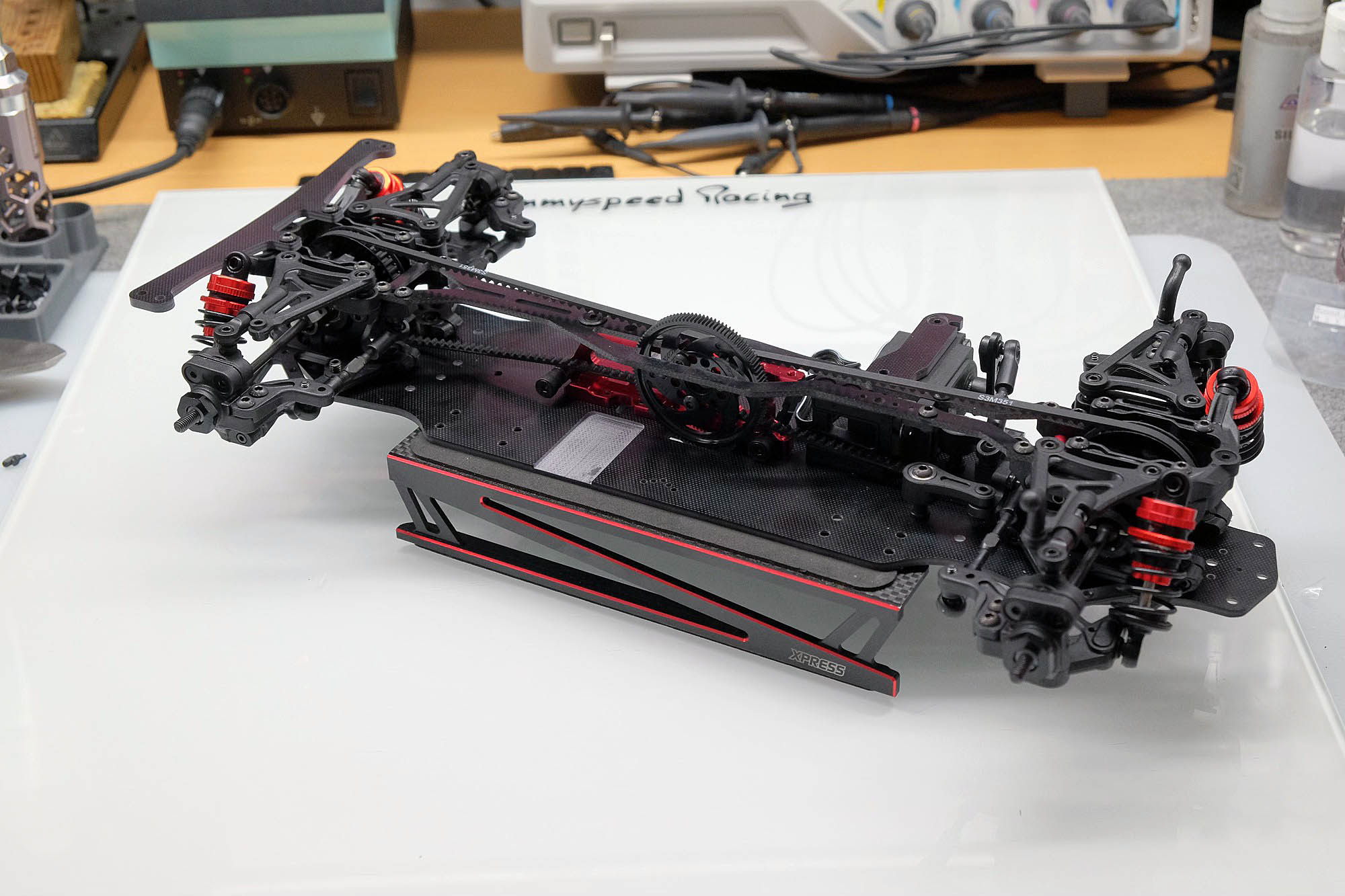
FINAL THOUGHTS ON THE CAR
In my opinion, the XQ3S is a bang, with Xpress doing almost everything right and better than with the XQ2S. The fact that a mid-engine kit no longer needs to be purchased makes the XQ3S incredibly attractive in terms of price. The chassis geometry has been changed to a contemporary design that offers more adjustment options but is still reasonably easy to handle.
Nevertheless, the structure of the XQ3S was a little more complex compared to the XQ2S. Many things are different than what you are used to as an XQ2S driver and there are now new points to pay attention to. Just conscientiously building and adjusting the swingarms feels like it takes as much time as the entire suspension on the XQ2S. Nevertheless, with good information in the instructions, Xpress makes it easy to put things together correctly and properly in many places. The quality of the fits, at least with my kit, was so good that I didn't have to rework or ream anything.
I personally find it a shame that the actually good battery holder is once again part of this summary. On the XQ11 this could be remedied simply by leaving out the adjusting screw. Here with the XQ3S, a tinkering solution is once again required. The fact that the plastic feels significantly more brittle and harder compared to the previous variant is a bad sign of stability in the event of a crash...
In my opinion, the battery holder is the only real weak point on the XQ3S. The rest of the chassis offers an incredible number of good features, some of which were already foreseeable in advance, but are not a given given the price. Some people will probably portray the chassis as a plastic bomber or a poorly made copy of another chassis or whatever. Anyone who has built the XQ3S and taken care can be sure that they have a well-functioning chassis that has inherited many features and the contemporary chassis geometry from its big brother

FAQ AKA FREQUENTLY ASKED QUESTIONS
My front suspension is stuck – what can I do?- Are the lower swing arm bolts tightened too tightly? These should only be closed so far that the ball heads no longer have any vertical play, but the wings can still be moved easily and fall down again when they are raised.
- If the upper wishbones are stuck, it can help to unscrew one of the ball heads a quarter of a turn and check again. If necessary, repeat with the other ball head. If the ball heads themselves are not 100% straight, the distance between the two changes minimally. This can cause the upper wishbone to bind.
- Are the front drive shaft inner pins correctly centred? If this is not the case, the pin can get stuck in the spool exit when the suspension is raised. This gives the impression that the suspension is stuck, even though the drive shaft is actually responsible.
I have too few or no suitable screws for the rear body mount- See Body Mounts section in this report - screws other than those specified in the instructions must be used
-----------------------------------------------
For the sake of completeness, it should be mentioned here that I did not receive the kit, but paid for it entirely out of my own pocket.
Then why do you go to such lengths and not just drive in circles for yourself? Quite simply because I would have liked to have seen more reports like this when I started out. Not hymns of praise from some paid glossy magazines (which even back then left a lot to be desired), but honest reports from practical experience in which you can be sure that even sub-optimal things will be discussed and which will support you as best as possible in the development.
I try to implement this in my reports as best as I can. My attitude towards Variant that doesn't have to hide at all. Even the XQ11 as the spearhead is still around €240 cheaper than the comparable competition just mentioned.
|
