Maybe some of you have been waiting for this for a few days already, but I just did not have time to start until now. I’ll do this post as I have done in the past – updating it as the build proceeds over the next days.
Anyway, let’s get started on the TRF419X Chassis Kit.
The fact I received the car so early came as a bit of a surprise seeing that it had only just been announced, with a late June Japan release date.
Although I have posted some pictures of the box itself before, I think it makes for a good opening picture of this build post. I really like the clean design, and the TRF419X logo is very nice. The box is the same oversized one TRF kits have usually been packaged in.

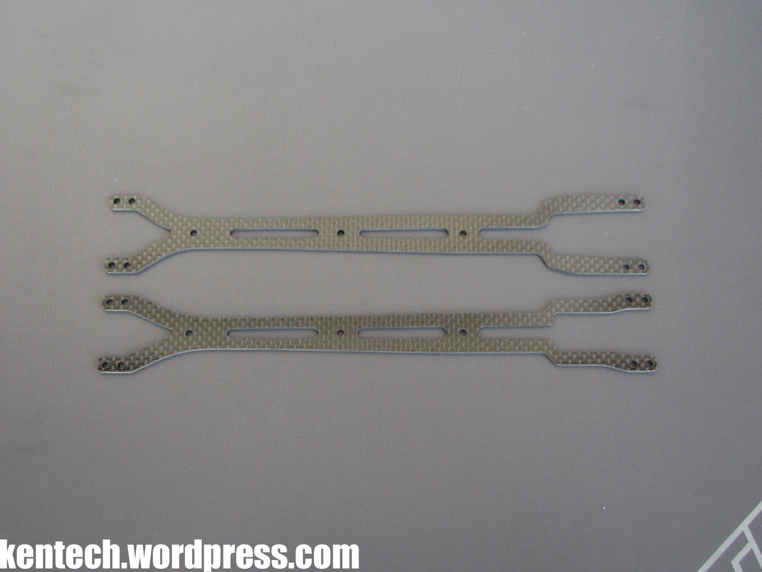
Next up, a complarison of the TRF419 (top) and TRF419X (bottom) lower decks. As you can see there are slight differences in the shapes, with the 419X version slightly more cutout at the edge towards the front, while less at the rear. The spur gear hole is smaller but it has a pocket on the right side opposite the motor pocket. Finally, there are no battery tape slots as the 419X comes with separate mounts for this.
TRF419
– width: 85mm
– thickness: 2.25mm
– weight: 71g
TRF419X
– width: 85mm
– thickness: 2.15mm
– weight: 69g
Other than the thickness, the carbon fibre material appears to be the same. A quick check with the lower decks on top of each other indicates that there are holes (1 in front, 2 rear) to allow you to fit the one-piece TRF419 motor mount if you wish.

The differences of the upper decks are quite obvious, with the TRF419X version slightly narrower. The front “V” cutout is a bit longer as well. Otherwise the shapes and cutouts are very similar. Thickness is the same at 2.0mm, and the material appears to be the same specification.
Here’s a look at some of the major new alu bits used in the first few steps of the TRF419X build.
The new bulkheads are familiar in style, but they are still brand new pieces with some difference in shape compared to the original TRF419. As you can see they don’t have the pins underneath them anymore. Instead there are three holes per bulkhead. Two (front & rear hole) are used when built according to the manual. You could obviously use a grub screw as a pin in the third hole if you wished, but the extra holes will be more useful for changing where you mount your bulkheads to the lower deck. This should have a fairly big influence on flex.
Also in this picture are the new left and right motor mount parts. This is sort of a step back to an older concept, compared to the one-piece motor mount on the 419. Also possibly, looking at the design of the parts, influenced by a certain orange car. The parts are light, with a total weight of 11.8g (L-8.6g, R-3.2g).
In the same picture you see the new fron separate 05G suspension blocks, but more of them in the following picture.

A comparison picture between the rear standard XA blocks and the new 05G blocks.
These new suspension mounts for the front are 0.5mm lower, for a lower roll centre. As can be clearly seen, they are also very wide. Following the normal marking by Tamiya, they are one step wider than the previously widest F block, 0.7mm wider.

The motor mount includes a center post (anodised black as you can see) whcih when built according to the manual, is attached via a grub screw to the motor mount front hole. Obviously, this is again a tuning option, and the post can be left out completely. In addition, the motor mount can be secured to the lower deck with any of the two front holes of the motor mount – alternatively both at the same time. Again, more flex options.

Front bulkheads and fron separate suspension blocks mounted to the lower deck. As you can see the partly black anodised trend continues with the new steering posts – finally with a hex shape at the bottom and not just round, making them a bit more reasonable to attach and remove!

Here you see the optional bulkhead mount holes I mentioned.

Rear part of chassis with bulkheads and motor mount attached.
The bulkheads have again moved in closer to the centre line, after they moved outwards on the original TRF419. The distance between them is now 22mm. A good idea when mounting these is to use a 22mm jig to press them against when tightening down the screws, to make sure your bulkheads are lined up straight.
The screws mounting the motor mount parts are very close to the centre line, with the distance between alu parts here only 8mm.

As I continue the build, next up is the rear gear diff assembly. The gear diff is exactly the same as on the original TRF419, so not much to mention. The same 900 weight clear oil is included, as has been the case on every TRF kit since gear diffs were introduced. The only exception is that only black joint o-rings are included. On the 419 you got a choice between the black o-rings and the softer red/brown o-rings.
Considering Tamiya made a completely new gear diff for the 419, it is no surprise to see it still featuring in the TRF419X it. However, since everyone (me included) seem to have had problems with leaky 419 diffs, it is still a bit disappointing. Even everytime you see a picture of a factory TRF drivers 419 from a race, the diff is wet. Other than that the diff is very smooth and workd well, but we should not have to deal with leaky stuff on 500 EUR kits.

Next up the new upper bulkheads, upper arm mounts and spacers.
On the right you see what you get in the kit; steel screws, steel ball connectors, blue anodised upper bulkheads, black anodised upper arm mounts, upper arm mount spacers and normal 3mm spacers.
On the left you see it as I chose to assemble the parts, with blue anodised alu screws, ball connectors and spacers.
I must say I really think it is a terrible idea with the mix of black anodised parts added to the normal Tamiya blue. When you have the best colour in the business and it is a trademark of your TRF cars, why move away towards something which make your cars look closer to the competition? It is as if it’s not enough to copy actual features of the competitors cars anymore…now you have to start copying looks and colours as well!? C’mon Tamiya…get a grip!
Anyway, rant over. Some people will like it but most everyone so far have just said: WHY??
The actual parts are really nicely made, with great finish and very solid once assembled thanks to the locating lug. Big plus for the proper adjustment spacers included as well, something most manufacturers would have left out. And I think the idea with the adjustable upper arm mounts is a good one.
The upper bulkheads are all the same, so you can use the same part on each four corners, while there is an “A” and a “B” typer upper arm mount.

Continuing the redesigned parts line, the spool, or direct holder in Tamiya lingo, got a new design to make it even lighter. One of the most beautiful parts on the car!
The outdrives, or direct cups, are the same as on the 419, i.e. lightened steel parts with no space for blades. The 418 had the version with blades (#54544) but it was found the no-blade version was better for durability.

This is what the rear end looks like with the drivetrain added and upper bulkheads attached.
As you can see I chose a 111T spur gear, but the same 116T spur as on the TRF419 is what you get with the X kit. Both the front and rear belts, as well as the center shaft and pulleys are the same. Also the plastic bearing holders and fluorine TRF bearings are the same.
I was slightly disappointed to see that the upper bulkheads again seemed to clamp the bearing holders too. In the end I used 0.2mm shims (3mm) under the upper bulkheads to make sure the bearings run as free as they should. We used to have to do this some years ago (maybe on the 417’s?) but got away from it with perfect fit on recent cars, so it should not really have made a comeback now.
The diffs are mounted “high” both front and rear, a first for any TRF car built to the instructions. Of course, the diff height also depends on the actual height of the bulkhead, not only the position of the adjustable bearing holder. Measuring from the lower deck, the diffs are mounted at the same height as on the 419.

Left side view of the rear bulkheads and motor mount.

Front bulkheads and drivetrain with spool, 37T pulley and steel outdrives installed. The upper arm mount stuff is the same as at the rear of the car.

In this view you can see how narrow the motor mount parts are where they mount to the lower deck, while the bulkheads are also closer together as already mentioned, with a distance between them of 22mm. On the TRF419, this distance was 24mm, so the bulkheads have moved out 1mm per side.
This also means that the car, or actually the type name/numbering, breaks a long tradition on TRF TC kits. Usually the lower deck has been compatible between cars of the same generation, i.e. on all TRF417 kits you could use any version of TRF417 lower deck as the screw pattern for the bulkheads etc. were always the same. This was the same on all versions of the TRF416 series as well. Not so on the TRF419 series, as you won’t be able to run an original 419 lower deck on your 419X, or vice versa.

The steering is exactly the same as on the previous TRF419. Here I have again replaced some screws, spacers and ball connectors with blue anodised aluminium parts.
You get the idea – I will continue to run my car as blue as possible…
The fact that the steering is the same as on the 419 means you can also run the recently released Samix Floating Steering Set on the 419X, as the servo mount holes are also exactly the same as on the 419.

The main frame of the TRF419X kit is now together as the upper deck is attached. Again, steel screws are included but I use blue alu screws from Tamiya.
The belt stabilizer has remained the same.

I added this picture to show you how close the upper deck is to both the left and right pulley. Without taking away material from the upper deck, it actually locked the center shaft in place because the upper deck was too tight. In this picture I have actually removed about 1mm from each side of the upper deck, to allow the drivetrain to spin freely. Again, not something we’re used to on TRF kits.
As usual I also removed a bit of material from the front and rear edges of the upper deck to make sure it won’t bind up the chassis and cause tweak issues.

Two more views of the completed chassis frame.


On to the suspension then, with both the front and rear arms new compared to the TRF419. While the basic shape shape, length and measurements of the arms are the same, there are still major differences.
The material the arms are made of has been changed, and in you look closely at the following picture you can see that the new arms (closer to you) are a bit more black and shiny, compared to the older version (further back). The weight of the arms is however still the same despite the material change (well, the new ones when measured were 0.1g heavier both front & rear). I have no further info on the differences between the materials.
You can also see that the damper attachment holes have moved on both front & rear arms. According to what I measured, on the front arms the damper position has moved in by 1.5mm. The distance from the centre of the suspension pin to the damper position is now 31mm. At the rear the damper position has moved outwards by 1mm. Pin to damper length is now 39.5mm.
The part number for the new arms, soon to be released, are:
54691 TRF419 D Parts (Suspension Arms)
The arms are marked with a small “B” to make identification easier.

More new parts and changes in the following picture, as the suspension balls are now made out of white plastic (would assume delrin) instead of the steel balls used until now.
I really don’t know why this has been changed so I can’t comment much. I would not be surprised if it again has something to do with mimicking what the competition use, while retaining the TRF suspension block system, but that it just a guess…
Maybe it has been tested properly and extensively and found to improve performance, and therefore included. Those who know are welcome to comment!:)
IMO it is a bit questionable to include these in the kit though, as they look and could be quite fragile, as well as easy to lose while working on your car, but only have a 7-digit special order spare parts number which mean they will be very hard to find for a long time.
Even though the “damper ball connector nuts” might look like the previously available option parts (#42231), they are in fact a new part. They are still fluorine coated and use a 2.5mm hex wrench, but they are 1.5mm lower compared to the old part.
Ti-nitride coated suspension pins are again included in the kit.

In the kit you get XA and E blocks for the rear, giving 3 degreed or toe-in per side.
In continuing the theme of everything is a bit different on this compared to the first 419, the one-piece 1E suspension block is now the standard type used since the 416 series already (1E – #54073). If you remember, the 419 kit released late 2014 had suspension mounts slightly strengthened, and with a 7-digit special order number. That’s why I included the 1F block (from the 419) in this picture for comparison.
Also in the picture is the one-piece 05G mount for the FF position. This has no normal spare parts number, just like most of the new parts on this kit. Only 7-digit special order numbers.

Rear arms mounted to the chassis. 1mm spacers behind the damper ball connector nuts (yes I used the black ones included here as I don’t have an infinite supply of blues…).
On the suspension pins, the total amount of spacers in the instruction manual has usually been 4.5mm, while I have ususally used 4.3mm to allow the arms to move freely. This time, the manual suggests you use 4.3mm, but I went down to 4.0mm to get them to move freely.
As you can see, I built the car with a 1D (#53072) block in the RR position, for 2.5 degrees of toe-in per side. Other than this and some other diff and damper oil, I am building this kit as per instructions. 2.5 deg has usually always worked best for me so that’s why I choose that as a starting point.

The new front arms attached with the low n’ wide 05G mount. 3mm of spacers in front of the arm and 1mm behind it. Remember, black spacers for everywhere is what you get in the kit. No spacers behind the damper ball connector nuts at the front.

The rear uprights were renewed as well.
There are several differences. The previous (418/418) upright had a total height of 29mm. The new 419X uprights have a total height of 31.5mm, with material added at the top where we have usually been running 3-4mm of spacers.
In addition the pin – axle distance is 0.5mm more on the new uprights.The bearings also appear to sit 0.5mm further inwards on the 419X upright, in effect making the rear end 0.5mm narrower per side.
As you can see from the picture, the newer upright looks like it has more fibres in it, so another material change here. Because of the different shapes, it is impossible to make a direct comparison on weight as the new one has more material in it. Anyway, weights were 2.2g for the old, 2.4g for the new.
The new rear uprights also have a “B” marking to distinguish them from the previous 418/419 upright.
The part number for the new uprights, soon to be released, are:
54692 TRF419 E Parts (Rear Uprights)

The new rear uprights fit the car perfectly without additional shimming or shaving. The outer pins are also the same as for a long time now (#53917). The TRF 5x10mm bearings and bearings spacers are also the same, as are the 4mm wide hexes (#53570), and the 44mm alu driveshafts.

Front view of the rear suspension assembled. The driveshaft blades are the same as on the previous car.

At the front there are also some changes, although the steering blocks and c-blocks are still the same as on the 419. However, one change in this area that I only noticed when assembling the parts, is that the flanged kingpin tubes have been changed. They are new parts, and now require a shim on top of the steering block once more. The manual calls for a 0.5mm shim, but for free action I found a 0.3mm shim to be the right size. I can only assume this has been done to further lower the roll-centre at the front, to go with the new 05G blocks. The top 5x9mm kingpin ball connector is again normal version (not the 1mm lower version included in recent kits) I have been using all the time. This part has its own part number (9804381), but is also included in the #54075 kingpin set. The starting point setup calls for a 0.5mm spacer underneath the upper kingpin ball connector.

The TRF419X kit obviously includes Tamiya’s excellent double-joint driveshafts, but they are now the 46mm variant and not the 44mm version commonly used until now. This change is obviously to go with the new wider front end of the car.

OK, roll-bars then, and they pretty much follow what we have seen on both the TRF418 and TRF419 kits. There are some small changes though.
Perhaps the main change is that the one-piece rod stoppers are now included. This was released for the 419 as an option part, but obviously with the bulkheads closer together the 419X version is a new narrower part. Form and function is the same though, and overall it makes for an easier to more exactly setup roll-bar. The fluorine coated roll-bar ball connectors (different length F&R) which were released at the same time as the one-piece stopper last year, are also included.
The front bar is 1.3mm, while the rear bar is 1.2mm.
I had troble getting the front roll-bar to work as it should as there was some binding after assembling all the parts. I traced this to the balls moulded into the front arms, to which the 4mm adjusters connect to. In the end I had to sand them down a bit to get the free movement required. So my advice would be to check this before you start working on the front arms (step 15 in the manual) because it will save you from having to disassemble it all later.

I suspect many potential customers (me included) had wished for bearing supported roll-bars like much of the competition has. Made right that both works and looks good, bringing more precision to the roll-bars on these cars. The system used on the 419 is light and no big problem, but considering the roll-bars on these cars are still a bit flimsy and underdeveloped, it would have been good to see more of an effort made here.

Onto the new dampers, described by Tamiya as super short big bore dampers.
Let’s go through the following picture left to right, first the top row, then the bottom row.
– New 20mm short springs. Four of the same type included (part# 9804945). The springs are 1.4mm x 6.
– The lower spring retainer is listed as #42192, but while the part with this part is blue anodised, the ones included are black anodised. Other than that it is the same part.
– The rod guide cap is a completely new part, also black anodised, and much lower than previous parts.
– New cylinders, with an overall length of 18.6mm. The inner length, or depth if you like, is 15.4mm, while the inner diameter is 11.2mm. The “big bore” dampers introduced on the 419 had an inner diameter of 10.5mm. The cyliner again has a HL (high-lubrication) or “Kashima” coating.
– A blue spring adjuster, but it is still an all new part as well to go with the larger outer diameter of the new super short big bore dampers.
– The cylinder cap is a new black anodised part (actually the cylinder cap, cylinder, rod guide cap and spring adjuster all have the same part number #9804944, i.e. they come as a package). While new, it is very close to the TB04 damper cylinder caps with similar height, but there are small differences in measurements between the two. It is possible to fit the (blue) TB04 top cap though.
– On to the lower row, with the rod guide, which again is the very old #53574 rod guide. Kind of a shame that the very nice and solid precision rod guides of the 419 are now gone with these super short dampers.
– Blue TRF o-rings (#42137) are included, and together with the rod guide they are all that fits inside the new short dampers and the low profile rod guide caps.
– 23mm is the length of the new piston rods or damper shafts. Ti-nitride coated as we are used to on TRF kits.
– 4-hole pistons is what’s included, machined from a white material.
– Obviously new o-rings for the new spring adjusters.
– A new oil seal , or bladder, diaphragm, whatever you wanna call it, after many years of using the same part for this job.
– Furthest to the right the cylinder part of the damper as they come out of their bags, giving you an idea of what they will look like in this new mix of black and blue.
The damper plastic parts are still the same as always (#53334). No foam pieces are included anymore with these new dampers.
It’s perhaps worth noting the dimensions of Xray’s dampers, which we know was used by the factory drivers at some stages during the winter just passed. As you might have guessed, the measurements match quite closely. The dimensions for Xray dampers are:
overall cylinder length: 18.3mm
cylinder depth: 15mm
inner diameter: 11.2mm
piston rod: 23.1mm
The build of these new TRF super short big bore dampers went quite well without major issues. TRF dampers have always been easy to build and with good detail finish. The piston fits the shaft perfectly without any need for shims. The rest of the assembly process is just a case of the normal procedures. The only question mark I had was that the bladder did not seem to have the same perfect fit as we have been used to and made closing the damper a bit more tricky. In the end all dampers were equal though, so I guess it’s all good.
I built my dampers to 54.5mm overall length, and this seemed about right when fitted to the car. All screwed in they are around 54.0mm. As always you get the yellow Tamiya 400 oil with the kit – I used Muchmore 450 as a starting point.

The new low profile damper stays, 3mm thick, fitted to the car. You can see that the number of damper mounting positions have been reduced to 4 both front and rear. Number 2 (from the inside) is used F & R when built according to the manual.
The damper stays are attached with 2 countersunk screws and 2 round head screws. Where the round head screws go, a bit of material has been machined away to reset the screw into the carbon fibre (that’s why I left out one screw to leave it visible for the photo).


New low profile damper ball connector nuts are used to secure the dampers, as I already mentioned during an earlier stage of the build.
You can see that I have used some blue spring retainers in place of the black ones included, as I strive to replace as much of the black with blue bits.


Finally, a side view showing the new lower profile of the TRF419X with these super short big bore dampers. The highest point of the front damper stay is at around 55mm from the bottom of the lower deck, when this distance was around 61mm on the TRF419.

After years of all aluminium floating servo mounts (417V5, 418, 419), Tamiya decided to go with a multi-piece alu + carbon servo mount for the TRF419X. This is what it looks like when assembled with aluminium screws. Overall it is very solid piece with good precision and execution. The carbon fibre is 3mm thick, and the weight it almost exactly the same as the previous one-piece alu servo mounts.
I noticed now there is some dust on it in the picture…sorry folks!:)

This is what it looks like in the car. As I wrote, it’s very solid and not really any flex in the part. I already mentioned previously in this build report that the mounting to the lower deck is the same as until now (pin and 2 screws), as is the positioning of it in relation to the steering. This means you can run any of the previous servo mounts should you wish to do so. It also means you can run the Samix TRF419 Floating Steering System.

A welcome addition to the TRF419X kit is that you get some good screw-on ballast weights included with the car. Here you see the center ballast weight (30g), which is attached with only one screw, but also kept in position with a pin. It also “floats” above the lower deck with it only touching the carbon plate around the screw. This is the correct way to make a screw-on weight that stays where it’s supposed to, but has a minimal effect on flex.

In this picture you see one of the two front ballast weights (10g) included. A similar design to the center weight, with holes for attaching them at the front of the chassis under the steering.
The picture also shows you the front battery holder. The fastening of it to the lower deck follows the same thought as the weights. Made from black anodised aluminium, it will support the battery from moving forwards in a crash while doubling as a mount for the battery tape.

The rear batteri holder is held to the lower deck the same way as the front, with one screw and a pin, but the rear mount is also adjustable so you can adjust for different size batteries.
A very thin rubber tape is also included to be placed under where the battery goes. This helps hold the battery in place without having to tape the battery in overly tight. Another small trick to help the flex of the chassis frame. The tape is even thinner than the popular Yokomo tape, and easier to use.
You will notice there are some screw holes in the center ballast weight which could be used to adjust the battery, but the weight is positioned such that it in itself will position the battery where you want it in most cases.

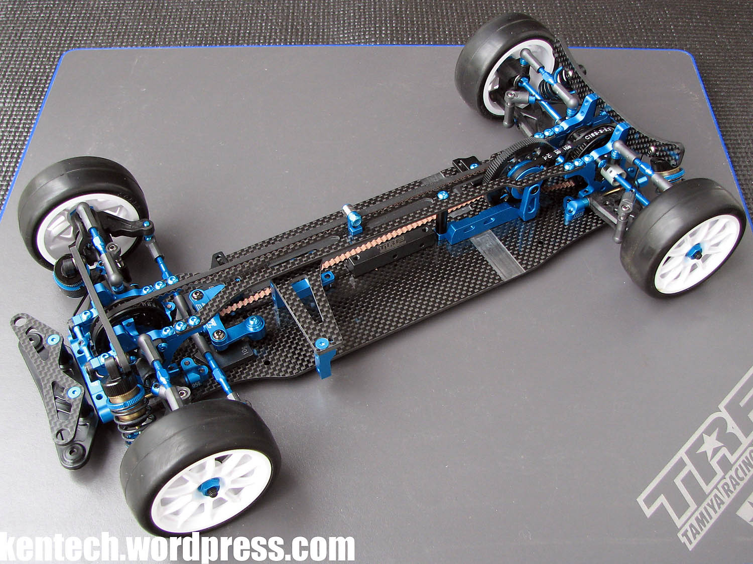
Finally some pictures of the TRF419X chassis in it’s complete form. Hope you enjoyed the build! I might add some pictures with tyres on later.


A final few pictures of the 42301 TRF419X Chassis Kit.
As I wrote last night, I hope you enjoyed getting a closer look at this kit at such an early stage.
I have added some info in the text in some places so you might want to go through the complete post again if you’re interested. If I notice some new details or remember something I thought about mentioning but forgot, I will add it still. But for now, this build review is done.
Ask in comments if you have questions. Thank you for reading.


First TRF419X Test
I finally did a proper full-day test with the TRF419X, after the first test rained away, and was followed by the first running with the car straight in a race with bad conditions, which you can read about in an earlier post.
Now, even if it was a full day at the track and lots of heats run, it was still only one day and look forward to more testing.
For this test I focused on the dampers and springs, trying to figure out what works and in what conditions.
The 419X performed well all day after the worst of the dust had disappeared, and some sort of racing line had formed. The biggest improvement of the day was going up to 5000 weight diff oil. After this the car was already very good, and it was easy to work on testing different damper and spring setups.
With the short dampers, I settled on 450 oil and SMJ springs, although Xray springs work very well too. Still, I must say that again the car was a bit faster and felt best with the TRF419 normal length dampers and springs on TRF418 towers.
I did the best laps and results with the longer dampers, and the feeling for the car was also better. The best combination for the conditions were X-Gear springs and 450 oil.
I won’t post any setup until I have done more testing.
It is obvious that the 419X works very well (both with the std super-short dampers and the older 419 dampers). But I do need to test more with both setups, as well as testing other setup options as well. But just wanted to post this short update for now.