Sealing carbon fiber is optional because of the quality of today's materials. That being said, I typically prepare my carbon fiber pieces by sanding, sealing, sanding and polishing. The results are a glossy finish, no sharp edges, and a smooth feel.
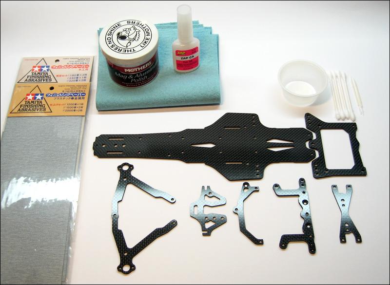
Layout of all pieces ready for chassis prep
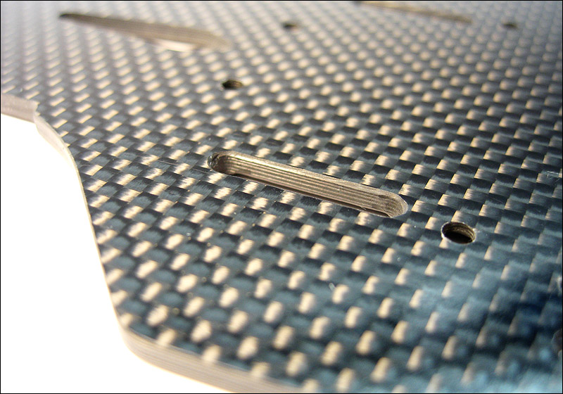
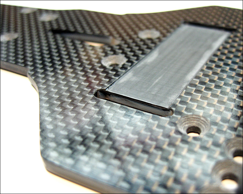
On the carbon fiber piece, I wet sanded with 180 grit to knock off the sharp edge. I also use a file or dremel to bevel and round the edges of the battery tape slots. This prevents any potential issues with battery tape getting cut, and money being ejected in a crash :D
Once done with sanding, I washed the carbon fiber pieces with soap and water. When dry, I wiped the edges clean with motorspray and a towel.
Here's a close up of the bevel/rounded edges
Finally, I applied two thin coats of CA with a cotton swab. For those hard to reach places, I used a toothpick.
A couple of tips on sealing with CA:
Avoid applying glue under fluorescent light. The UV rays accelerate the cure time and can result in a rough, orange-peel finish.
Try to seal with a warm ambient temperature, somewhere between 75-90 degrees F. If it's too cold, a white haze or residue will form.
Apply thin layers and allow proper drying time between coats. It was about 85 degrees today and glue was drying fast.
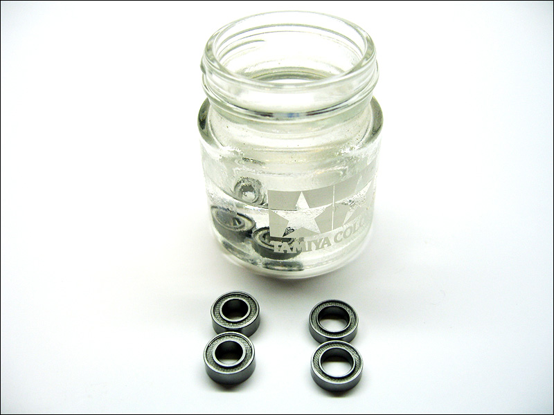
Bearing Prep:
Since the TRF 101 comes with bearings that aren't packed with grease, I simply placed them in a jar of motorspray and set them aside until needed. Again, this is only for the axle bearings. I did not do this for differential bearings.
Here is the rest of chassis prep...
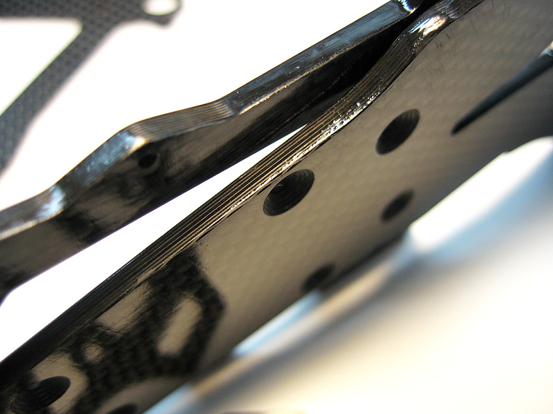
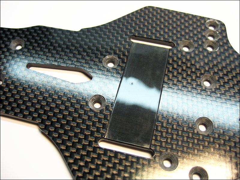
CF edges sealed with CA
CF after wet sanding with progressively finer grits of sand paper
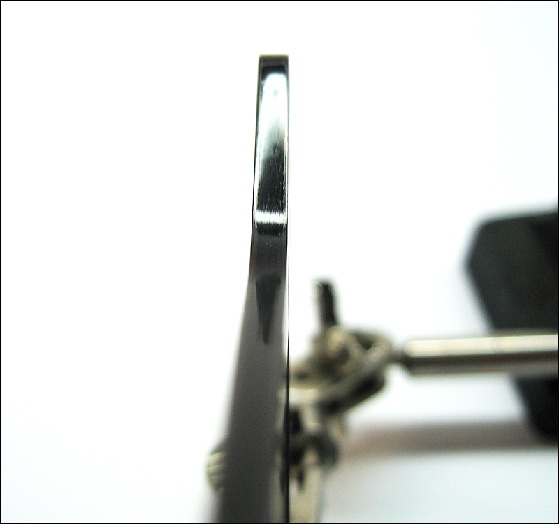
CF after polishing with Mother's Chrome Polish
Please note the following:
Carbon reinforced parts were used instead of the kit supplied plastics
Titanium and aluminum fasteners will be used everywhere.
Carbon reinforced side links are directional. If they don't pop onto the pivot balls easily, flip them over.
Additionally, the titanium 2x6mm screws will go through a side link hole easily and bite into the other side. Position the side links so that the screw head is on the outside.
Ideally, the assembly consisting of rear lower brace, side links, pivot ball, center pivot, and lower deck should be as straight, smooth, and as slop free as possible. Take time when tightening screws to ensure that they don't bind any movement. F1 guru Rob King (aka robk) has an excellent video demonstrating his process in his rcF1blog website. Again, take time adjusting screw tightness.
My US kit (purchased domestically) has a production issue. I've sent a message to the mother ship and hopefully I was just an unlucky lottery winner with this kit.
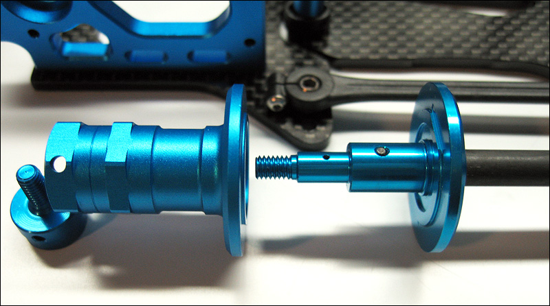
Assemble the rear pod on a flat surface. Make sure the left and right motor mount as well as rear bulkhead plate are as straight as possible.
When attaching the rear shaft, a microscopic amount of side to side play is desireable. Certainly less than 0.1mm, as little as possible to prevent the bearings from binding. Adjust as necessary before fully tightening the grub and cap screw that holds the left wheel stopper.
Some one mentioned how the 101's rear end retains the same width as the older cars. The new car uses new parts.
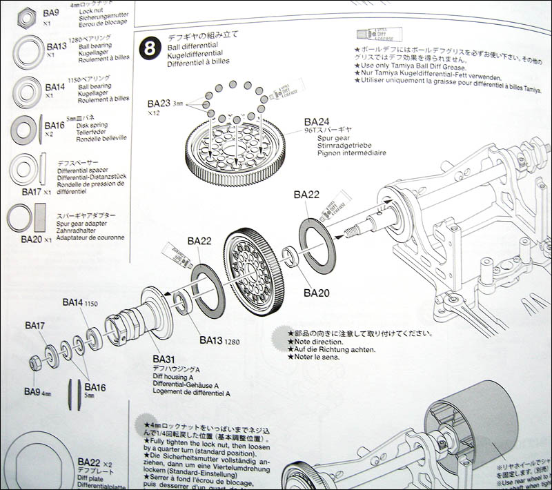
A spur gear adapter and an extra 12x8mm bearing is included in the kit. The manual (step 8 shown below) instructs the use of a 96 tooth spur, 12 3mm bearings, and the spur adapter.
Leave the differential somewhat loose and do not fully tighten. Adjust differential tightness after break-in at the track.
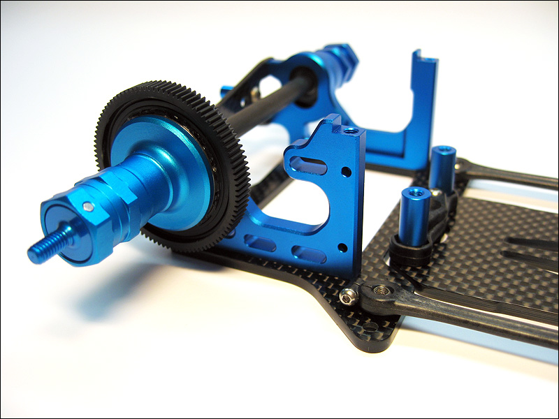
Parts for the rear shaft assembly. The inner diff housing comes premounted on the carbon fiber shaft.
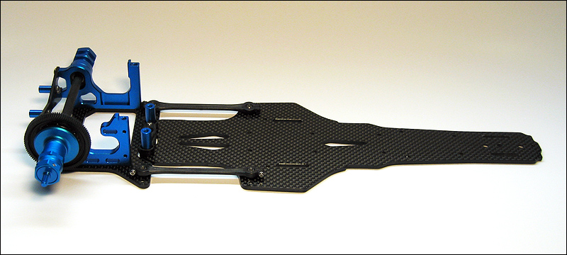
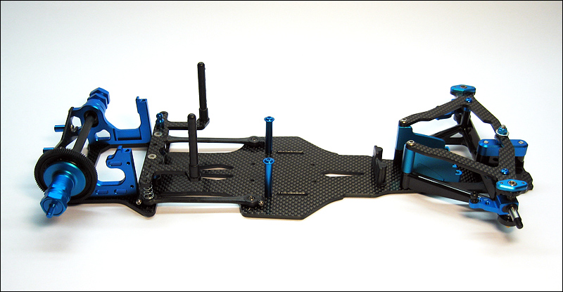
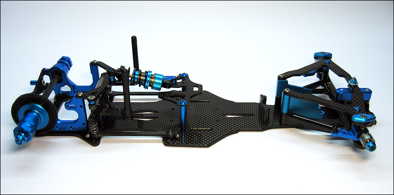
Steps 1-10 completed
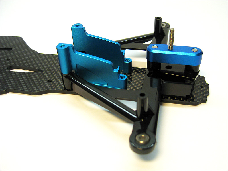
Close up of the rear end assembly
Photo of Step 8
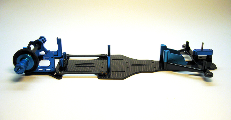
Steps 12-16 completed
Steps 17-19 completed
Notes:
Applied a small amount of loctite to all hardware attached to uprights.
Replaced the silver 3x3mm grub screws with shorter black grub screws. This allows the 3x5mm low profile screw to fully set and not get scratched by the silver grub screw.
This might be overkill, but I applied a small amount of Loctite to the 2x6mm screws that attach the king pin mounts to the front upper arm.
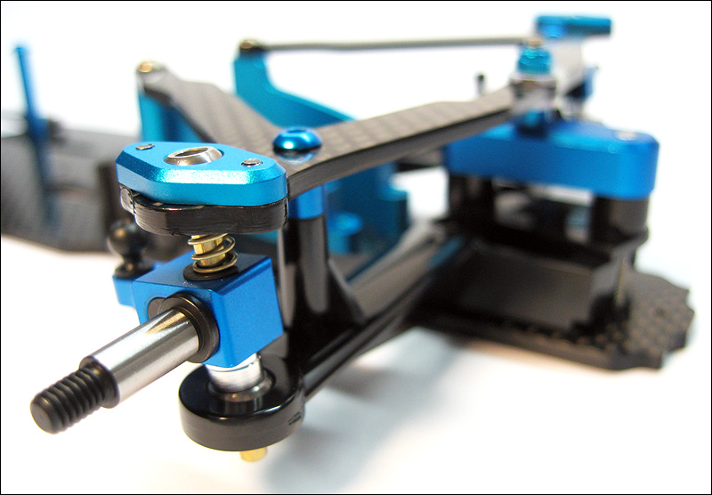
Close up of front suspension
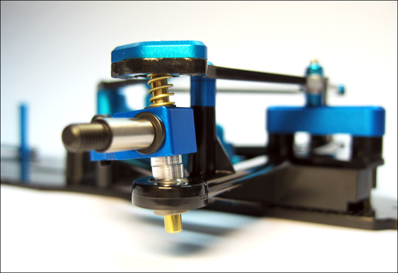
Another close up of front suspension
Steps 20-25 completed
Notes:
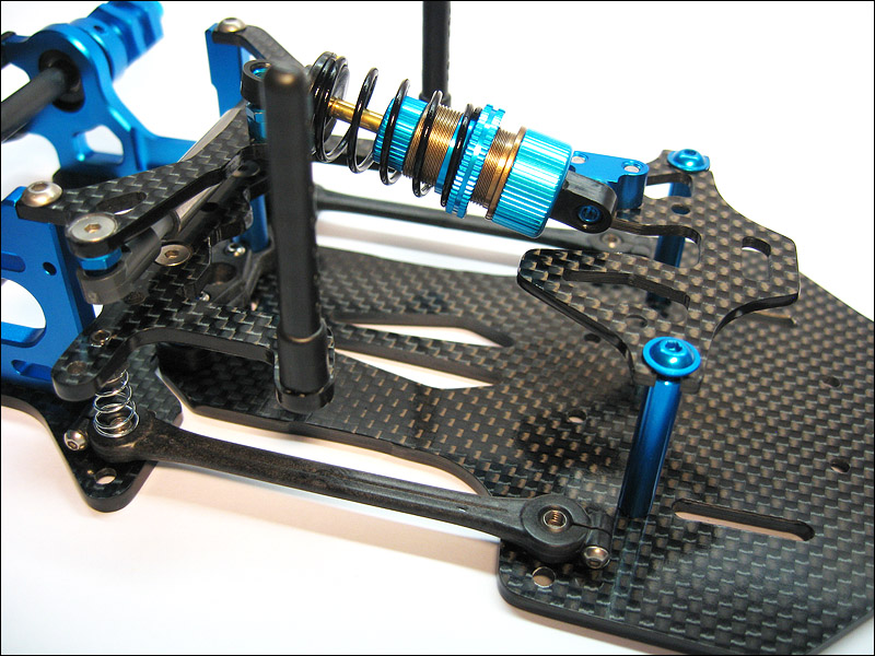
3.5mm along with an o-ring were used in the pitch damper. I rebuilt the shock 4 times to get rear droop to be slightly below level with 3mm spacers under the middle brace's ball connector.
Tamiya soft friction damper grease was used on the roll damper.