|

May 11th 1977, Tamiya releases their first
Formula 1 radio controlled model car, the Tyrrell P34 Six Wheeler. 32
years later, interest in Formula 1 continues to be as strong as ever and
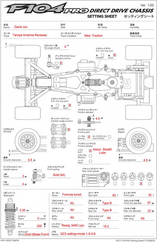
Tamiya releases their latest Formula 1 chassis, the F104 Pro.
 The
successor to the popular F103 chassis, the F104 Pro brings more features
and realistic dimensions of the modern Formula 1 car. Complete with a new
late generation Formula 1 body, the F104 Pro is well equipped with the
most desirable components and features. The
successor to the popular F103 chassis, the F104 Pro brings more features
and realistic dimensions of the modern Formula 1 car. Complete with a new
late generation Formula 1 body, the F104 Pro is well equipped with the
most desirable components and features.
Key Features:
3.2mm carbon fiber main chassis
2mm carbon fiber upper deck
Carbon fiber drive axle
Adjustable front and rear ride height
Adjustable front camber
Machined aluminum ball differential
assembly
TRF aluminum threaded body shock
Integrated rear diffuser
Carbon reinforced steering knuckles
Detailed 3 piece polycarbonate modern
Formula 1 body
 As
well equipped as the F104 Pro is, there is still an excellent selection of
Hop-Up parts to further elevate the performance of the F104. These Hop-Up
options offer a variety of benefits, such as increase durability, reduce
wear, improve tuning potential and enhance performance. The following are
just a few examples. As
well equipped as the F104 Pro is, there is still an excellent selection of
Hop-Up parts to further elevate the performance of the F104. These Hop-Up
options offer a variety of benefits, such as increase durability, reduce
wear, improve tuning potential and enhance performance. The following are
just a few examples.
F104 Hop-Up Options:
54176
- Formula-Tuned Motor (32 turn)
54169
- F104 Aluminum Pivot Post
54168
- F104 Sponge Tires Type B Rear
54167
- F104 Sponge Tires Type B Front
54166
- F104 Aluminum Motor Mount
54165
- F104 Soft T-Bar
54160
- F104 Titanium Nitride Coated King Pins
54159
- F104 Hi Torque Servo Saver Horn
54157
- F104 Titanium Screw Set
54138
- F103 Low Friction Pads
53918
- TRF Damper Low Friction V-Parts
53906
- 5x5mm Aluminum Ball Connector
Building the F104
Because it's easier to add Hop-Up parts to a car during the build, have
any additional Hop-Up items you've selected on hand prior to assembly. If
you're unsure of which additional Hop-Ups should be considered, I
recommend the soft T-Bar (54165), the Aluminum Motor Mount (54166) and a
softer rear shock spring. I found the M04 front shock spring (9805921) to
be a noticeable improvement over the kit spring under medium to low
traction surfaces. The soft T-Bar and the M04 spring improves the cars
compliancy and stability over bumps while the aluminum motor mount
maintains cooler motor temperatures. One final item I recommend is a
Kimbrough servo saver (standard size). In addition to protecting the servo
gears from impacts, the servo saver effects ackerman and bump steer. With
all the additional Hop-Ups and parts on hand, assembling the F104 is very
easy. In fact, there are only a few areas that can benefit from extra
attention during the build process.
Rear Pod
The rear pod of the F104 consists of 4 pieces, so it's important that they
are aligned properly to avoid any twisting. Start by assembling all 4
components together as per instructions but do not completely tighten the
screws. The screws should be just loose enough for the 4 pieces to move
around a little. Place the rear pod assembly on a flat surface such as a
set-up board and hold down only the left and right portions of the pod.
While maintaining moderate pressure, gently begin tightening the 8 screws.
Rather than completely tightening one screw at a time, tighten each screw
slightly in equal increments and repeat this process until they're all
completely tight. Lightly tap on the corners of the pod periodically to
check alignment during the gradual tightening process to insure the pod
isn't twisting.
Steering / Servo Position
 The
length of the servo saver arm and the angle of the steering links will
directly affect the amount of Ackerman and bump steer the steering will
have. I settled on the Kimbrough servo saver because it provided the
steering characteristics I was looking for. On the Kimbrough servo saver,
the two 5x5mm ball ends should be installed on the farthest row of holes
(end of the servo arm). The
length of the servo saver arm and the angle of the steering links will
directly affect the amount of Ackerman and bump steer the steering will
have. I settled on the Kimbrough servo saver because it provided the
steering characteristics I was looking for. On the Kimbrough servo saver,
the two 5x5mm ball ends should be installed on the farthest row of holes
(end of the servo arm).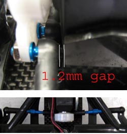
When installing the servo, the instructions
illustrate that the center of the servo output shaft should be 30mm from
the chassis. I used a Futaba 9602 mini servo and raised the height to 32mm
to reduce bump steer a little and this also affects the Ackerman slightly
as well. The fore and aft position of the servo also effects Ackerman. For
reference, I set a 1.2mm gap between the plastic ball end and the front of
the servo mount. This is roughly a 5 deg. angle in the steering linkages.
(Your potential range in servo position
will vary depending on the size of the servo used.)
When installing the servo, the instructions
illustrate that the center of the servo output shaft should be 30mm from
the chassis. I used a Futaba 9602 mini servo and raised the height to 32mm
to reduce bump steer a little and this also affects the ackerman slightly
as well. The fore and aft position of the servo also effects ackerman. For
reference, I set a 1.2mm gap between the plastic ball end and the front of
the servo mount. This is roughly a 5 deg. angle in the steering linkages.
Electronics
LRP QC3 Speed control
Futaba R603FF Receiver
Futaba S9602 Servo
Reedy 3400mah Lipo Battery
Tamiya "Silver Can"/Tamiya Formula Tuned 32T
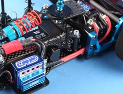 Although
installation of the electronics is easy on the F104, special attention
should be placed on the motor wiring because it can affect the handling of
the car. To begin, there are two areas to mount the receiver and speed
control on the F104. The logical position of the speed control is on the
left because the motor leads come off the left side of the rear pod.
Rather than placing the speed control in a typical bottom down position, I
placed it on its side with the wires pointing back. This enabled the
battery and motor wires to travel in a more direct path. Although
installation of the electronics is easy on the F104, special attention
should be placed on the motor wiring because it can affect the handling of
the car. To begin, there are two areas to mount the receiver and speed
control on the F104. The logical position of the speed control is on the
left because the motor leads come off the left side of the rear pod.
Rather than placing the speed control in a typical bottom down position, I
placed it on its side with the wires pointing back. This enabled the
battery and motor wires to travel in a more direct path.
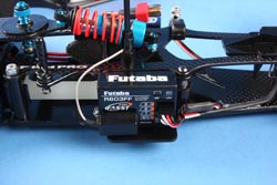 Regarding
wires, it's not necessary to have excessively thick gauge wire because it
can limit free movement of the motor pod resulting in handling problems.
To avoid this, I used 16 gauge wire to insure the motor pod moved with
minimal interference. The receiver installation is straight forward. To
allow plenty of clearance for the body, it was also placed on its side
with the antenna pointing rearward. This creates a clean path for the
speed control and servo wires to reach the receiver ports. Regarding
wires, it's not necessary to have excessively thick gauge wire because it
can limit free movement of the motor pod resulting in handling problems.
To avoid this, I used 16 gauge wire to insure the motor pod moved with
minimal interference. The receiver installation is straight forward. To
allow plenty of clearance for the body, it was also placed on its side
with the antenna pointing rearward. This creates a clean path for the
speed control and servo wires to reach the receiver ports.
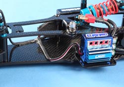 Due
to the very scale nature of the F104 Pro's body, the receiver sits on the
opposite side of the speed control with the battery running down the
center. This doesn't make installation of the electronics difficult but
the speed control wire typically goes over the upper deck to reach the
receiver. I prefer to have this wire less visible so I routed it under the
battery. Due
to the very scale nature of the F104 Pro's body, the receiver sits on the
opposite side of the speed control with the battery running down the
center. This doesn't make installation of the electronics difficult but
the speed control wire typically goes over the upper deck to reach the
receiver. I prefer to have this wire less visible so I routed it under the
battery.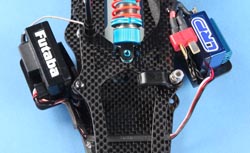 Start by adding shrink tubing around the area that will be under the
battery. This will avoid wear on the wire from installation and removal of
the battery. Make sure to have enough slack in the wire next to the speed
control to account for movement during battery installation/removal. Most
Lipo batteries have slots on the bottom to lock into a chassis design for
Sub C packs so with the heat shrink in place; use Shoe Goo to mount the
wire on the chassis so that it sits between these slots. I also used heat
shrink on the servo wire and used Shoe Goo to secure it down the right
side of the chassis. The end result will be not only a clean appearance
but a functional one.
Start by adding shrink tubing around the area that will be under the
battery. This will avoid wear on the wire from installation and removal of
the battery. Make sure to have enough slack in the wire next to the speed
control to account for movement during battery installation/removal. Most
Lipo batteries have slots on the bottom to lock into a chassis design for
Sub C packs so with the heat shrink in place; use Shoe Goo to mount the
wire on the chassis so that it sits between these slots. I also used heat
shrink on the servo wire and used Shoe Goo to secure it down the right
side of the chassis. The end result will be not only a clean appearance
but a functional one.
Shock and Damper Plate
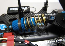 The
rear dampening system on the F104 Pro consists of an oil filled coil
spring shock for perpendicular dampening and a dual disk damper plate
assembly for 360 degree dampening of the rear pod. Because the damper
plate and the shock both control perpendicular damping and the T-plate is
firm in this direction, I went with the softest oil and spring combination
on the shock and light damper grease for the damper plate. Using the
3-hole piston, I used 200 weight oil in the shock and the front spring
from the M04 M-Chassis (gold color). This improved the overall compliance
over bumps. To control lateral movement of the pod, loosen or tighten the
adjustment screw on the T-plate. A loose setting will generally provide
more stability but reduce steering (good for low traction surfaces). A
tighter setting will increase response and provide more steering (good for
high traction surfaces). The
rear dampening system on the F104 Pro consists of an oil filled coil
spring shock for perpendicular dampening and a dual disk damper plate
assembly for 360 degree dampening of the rear pod. Because the damper
plate and the shock both control perpendicular damping and the T-plate is
firm in this direction, I went with the softest oil and spring combination
on the shock and light damper grease for the damper plate. Using the
3-hole piston, I used 200 weight oil in the shock and the front spring
from the M04 M-Chassis (gold color). This improved the overall compliance
over bumps. To control lateral movement of the pod, loosen or tighten the
adjustment screw on the T-plate. A loose setting will generally provide
more stability but reduce steering (good for low traction surfaces). A
tighter setting will increase response and provide more steering (good for
high traction surfaces).
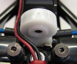
On the rear friction damper, add a 3mm
o-ring above the preload collar after assembly. This keeps the preload
setting from moving. In rare cases, the preload collar can completely
unthread itself without the added o-ring, so it's a good way to avoid this
from happening.
Tires & Gearing
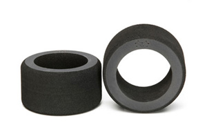 The
F104 Pro is equipped with the Tamiya Type A foam tires. These are a
relatively soft compound with a moderate amount of rubber content. The
optional Type B is a bit harder but with more rubber and this typically
generates more traction. For medium to low traction surfaces, the Type B
will most likely be the best choice between the two. The
F104 Pro is equipped with the Tamiya Type A foam tires. These are a
relatively soft compound with a moderate amount of rubber content. The
optional Type B is a bit harder but with more rubber and this typically
generates more traction. For medium to low traction surfaces, the Type B
will most likely be the best choice between the two.
For carpet or high traction surfaces, the
Type A may be better. Once you've selected your compound, the diameter is
very important because it affects your ride height, gearing (rear tires),
and overall handling. A smaller diameter tire tends to be more responsive
due to less sidewall flex but can have less overall grip than a larger
tire. In general, try a larger tire for low traction surfaces and a
smaller tire for high traction surfaces. A good starting diameter for low
grip surfaces is 60mm and 57mm for medium and higher grip. For very high
grip such as carpet, 55mm would be a good starting point.
Deciding on the gearing for your F104 will
depend on the motor you'll be using, the size of the track and the
diameter of your rear tires. The F104 Pro includes two spur gears sizes, a
104 tooth and a 93 tooth. For motors such as a "silver can" and
the Formula Tuned, the 93 tooth spur will be ideal in most cases. For high
powered motors, the 104 tooth spur may give you the proper gearing range.
With your tire diameter determined, you can select your gearing. The best
way to calculate gearing is by "roll out". This is the distance
the car will move per one rotation of the motor armature/rotor.
Roll Out Formula:
Pinion x Tire Diameter x 3.142 / Spur = Roll Out
Example - 27 tooth pinion x 60mm tire x 3.142 / 93 tooth Spur = 54.7mm
Roll Out
General Roll Out Range:
"Silver Can" - 53mm to 56mm
Formula Tuned - 57mm to 60mm
Chassis
The F104 includes two optional chassis posts. If used, they must be
installed after the battery is installed and removed before the battery
can be removed. The purpose is to make the chassis flex characteristics
symmetrical. I found that on medium to low traction surfaces, the benefit
is marginal. However, a high traction surface may justify the use of the
optional posts.
Differential
The differential is a very important component of any direct drive car so
it's important to use the right differential grease. Differential grease
has a unique characteristic in relation to typical grease. It lubricates
the differential yet resists slipping on the differential rings. This
allows for a free rotating differential that is resistant to slipping. If
conventional grease is used, the balls will slip on the rings requiring
and excessively tight setting resulting in a poor handling car. For this
reason, you shouldn't use just any kind of grease. My personal preference
is Associated Stealth Lube.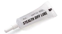
The setting of the differential will also
be determined by grip level and the power of the motor. The higher the
grip level and or powerful motors, the tighter the differential may need
to be to avoid slipping. In general, a differential that is too tight can
cause sudden loss of traction on a low grip surface yet in some cases,
under steer on high grip surfaces. A setting that is too loose will slip
excessively reducing drive exiting corners and will also create
inconsistent handling. For this reason, the setting will need to be tuned
to each condition. Typically, you want the differential to spin relatively
freely but not loose enough to cause slipping while exiting corners.
Tire Additive
  Tire
additive helps enhance the grip level of the tires. There are a variety of
options made specifically for hobby use. If you are unsure of which
additive to get, the most commonly used additive is Paragon Ground
Effects. This additive works by softening the foam and is suitable for
tarmac or carpet tracks. Tire
additive helps enhance the grip level of the tires. There are a variety of
options made specifically for hobby use. If you are unsure of which
additive to get, the most commonly used additive is Paragon Ground
Effects. This additive works by softening the foam and is suitable for
tarmac or carpet tracks.
The other recommended additive is sun
block. This may sound unusual but sun block has been used for outdoor foam
tire racing for as long as I can remember. Of course, there are a lot of
brands of sun block out there so I would suggest starting with Coppertone
SPF 30. Sun block tends to be used mostly on low to medium grip conditions
and is applied after the primary additive such as Paragon has been
applied. When using additive, the amount of time it is left on the tire
determines the level of effect. Apply additive to the full surface of the
rear tire for maximum rear grip but only the inside 1/4 of the front
tires. The amount of additive applied to the front can be increased or
decreased depending on the amount of steering desired. Also, experiment
with the duration you let the additive sit before wiping it off and
running. The longer the additive is left on the tire, the softer the tire
will become and the depth of absorption will also increase. |
