|
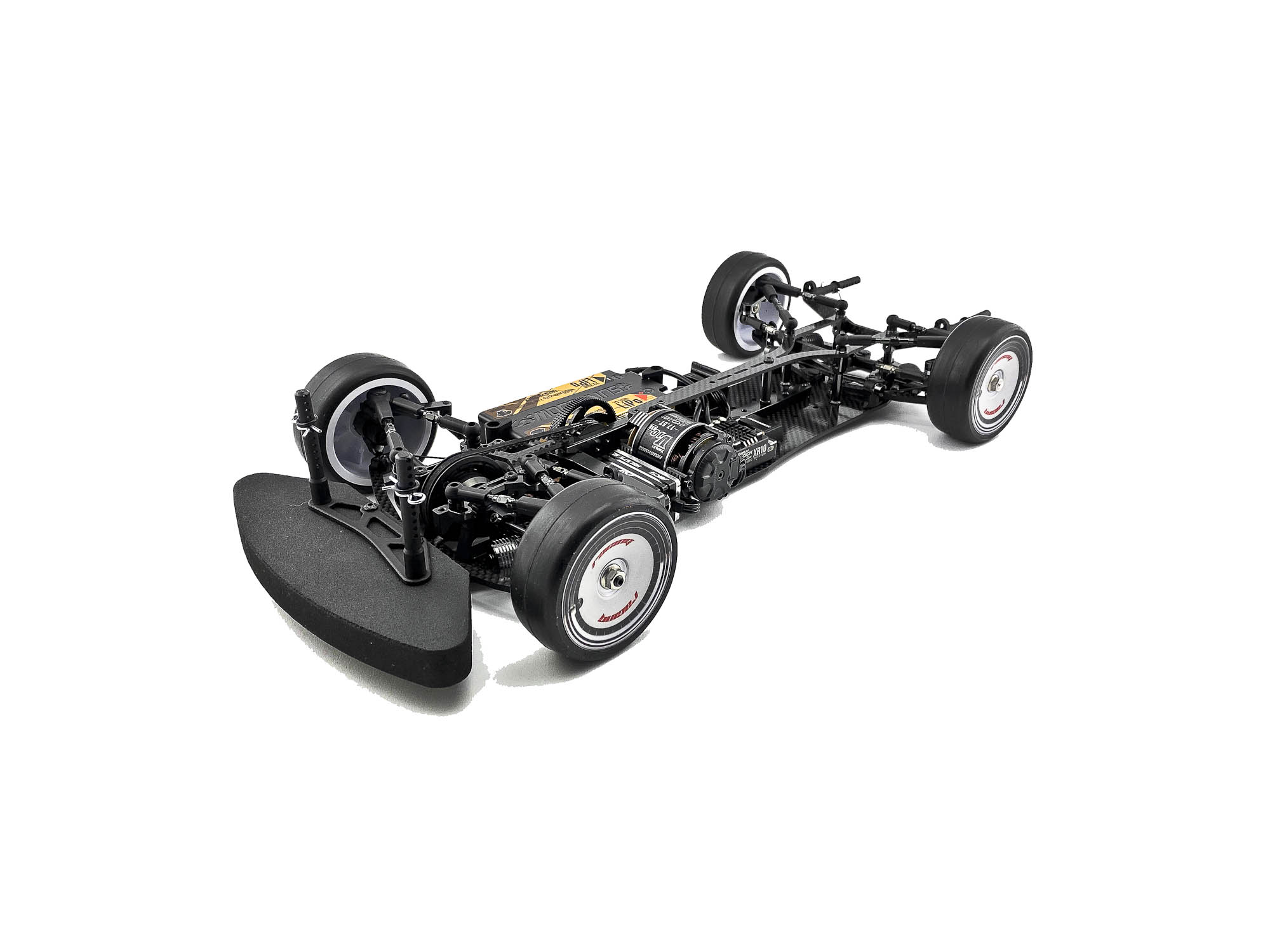
- Awesomatix A800FX Evo Build by Max Machler -
My annual build up of the new Awesomatix A800FX Evo kit is photo documented in this album.
Every picture of the album has some comments with some info's and tips.
Like always its possible that I may didn't follow the manual steps by 100%
Use the manual as main - and see my build tips as addition to it.
The new A800FX Evo is designed based upon the feedback from racers around the globe. Bigger setup window, bigger working range, and easier handling = more FUN and more SPEED !
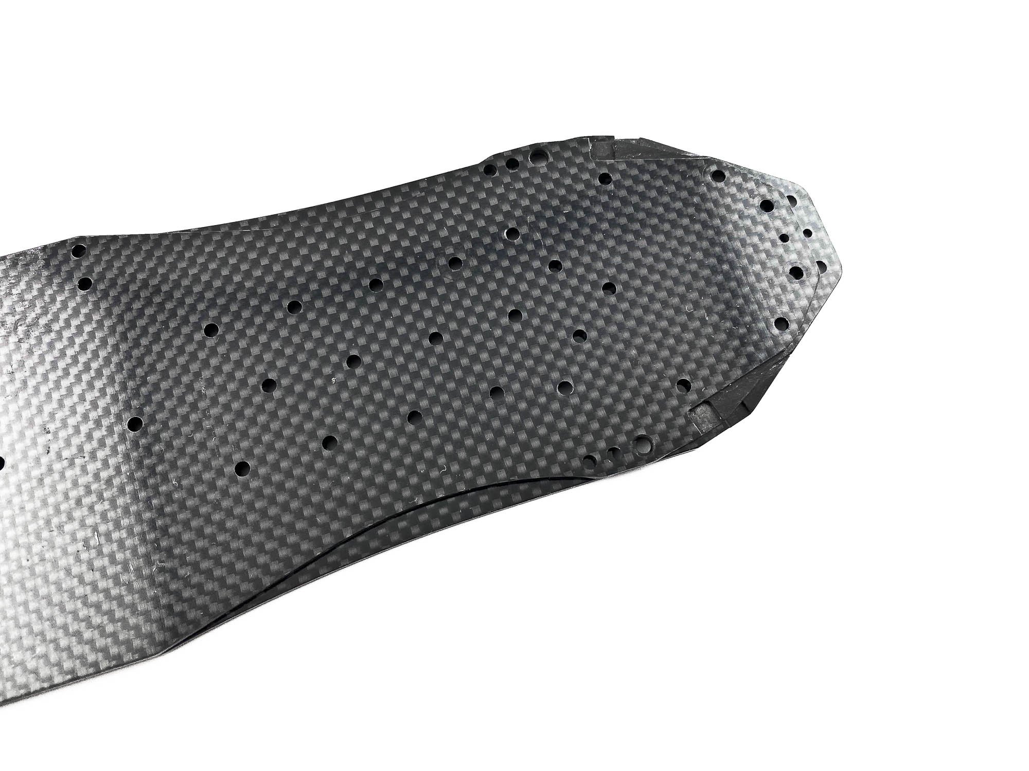
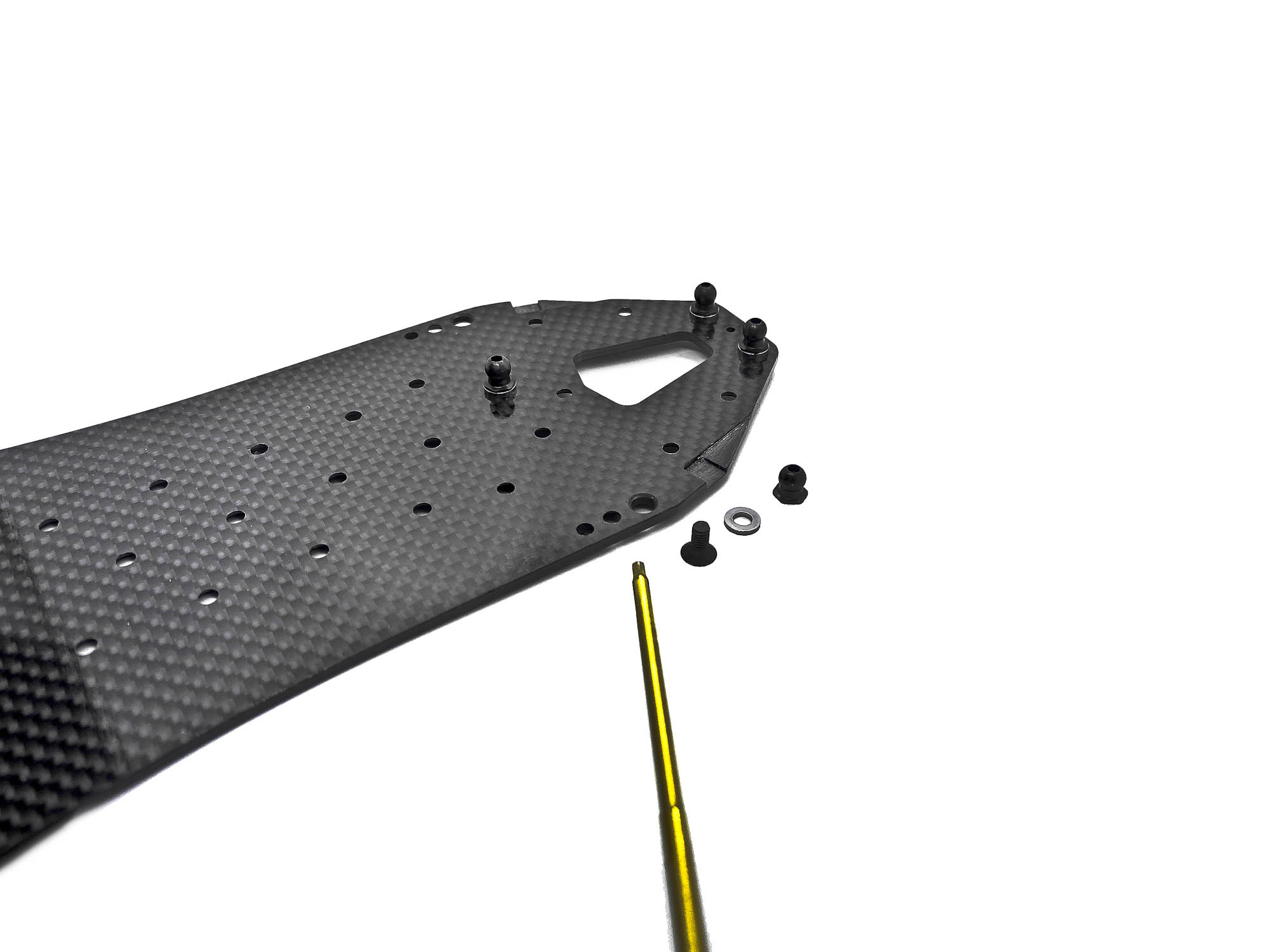
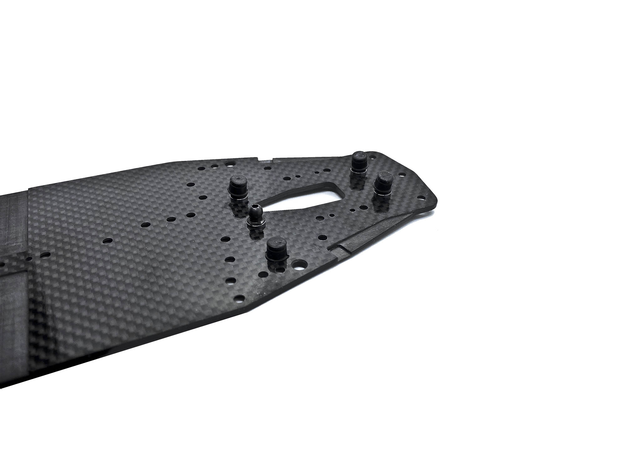
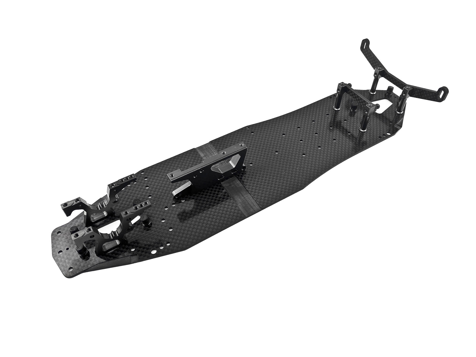
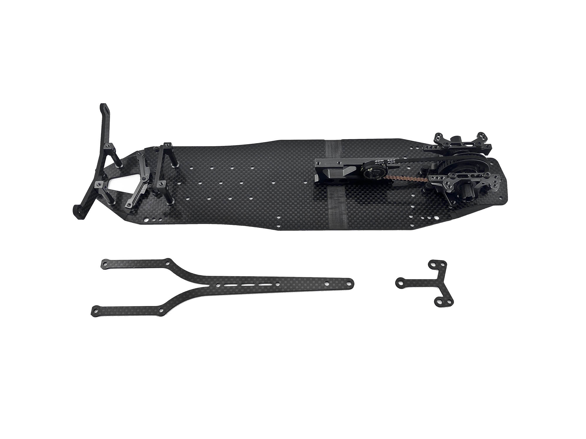
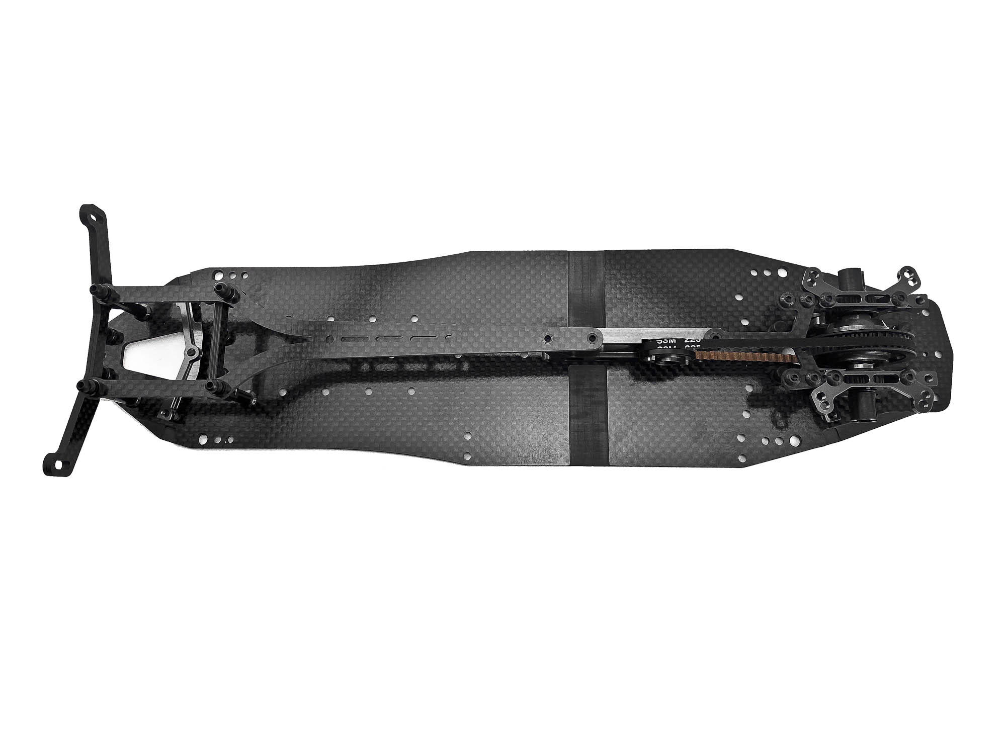
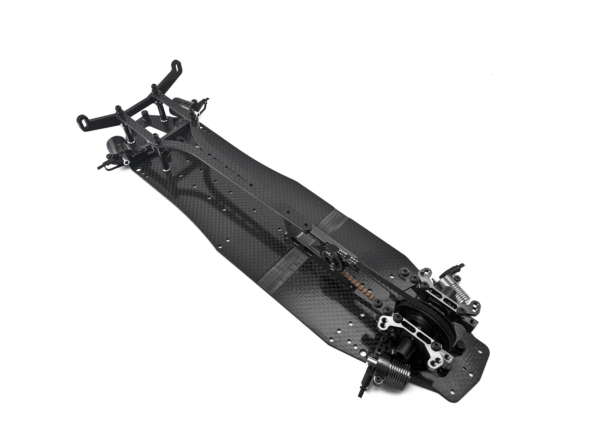
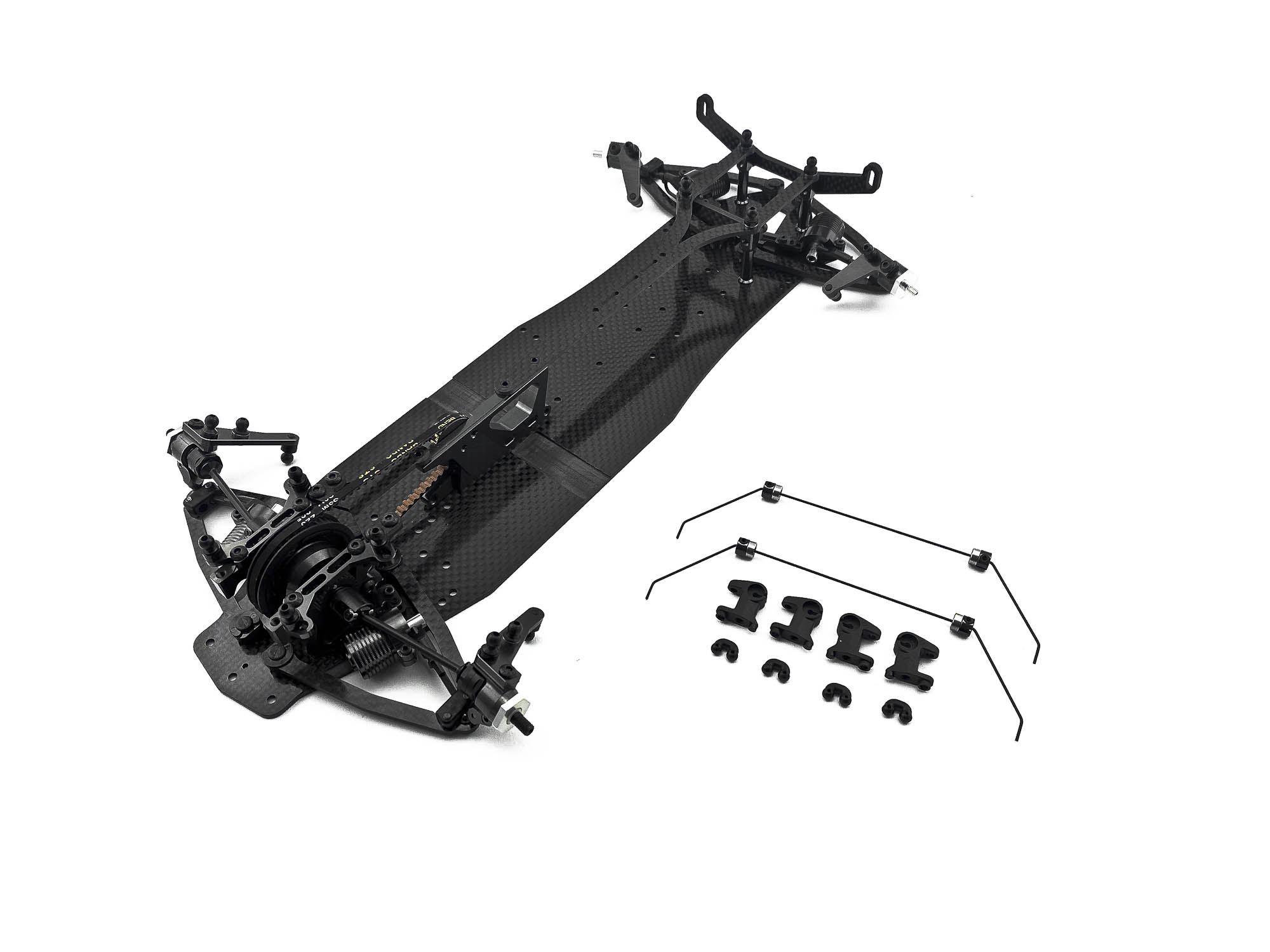
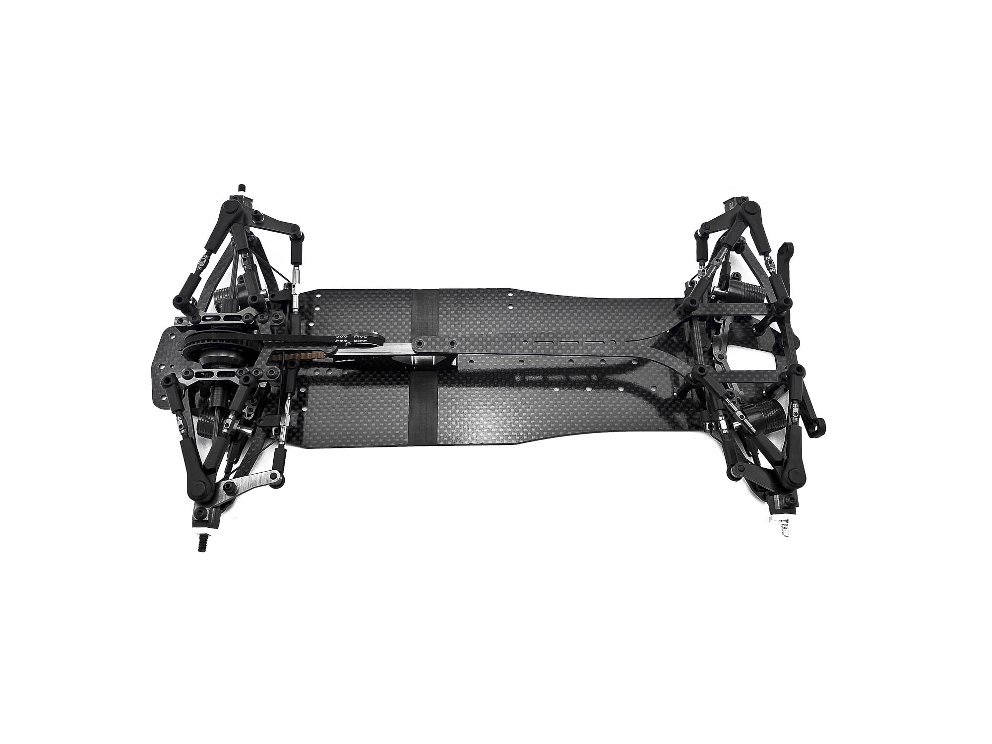
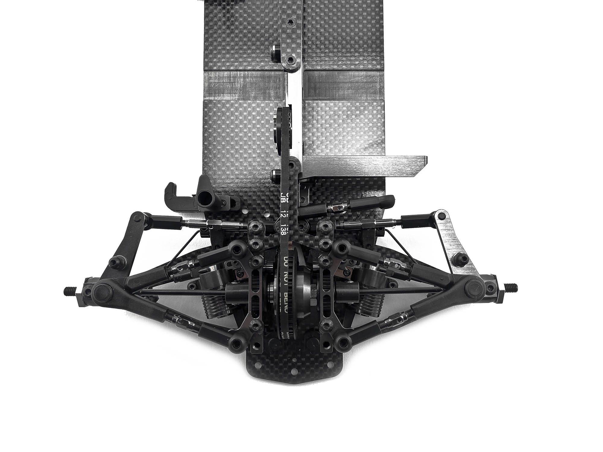
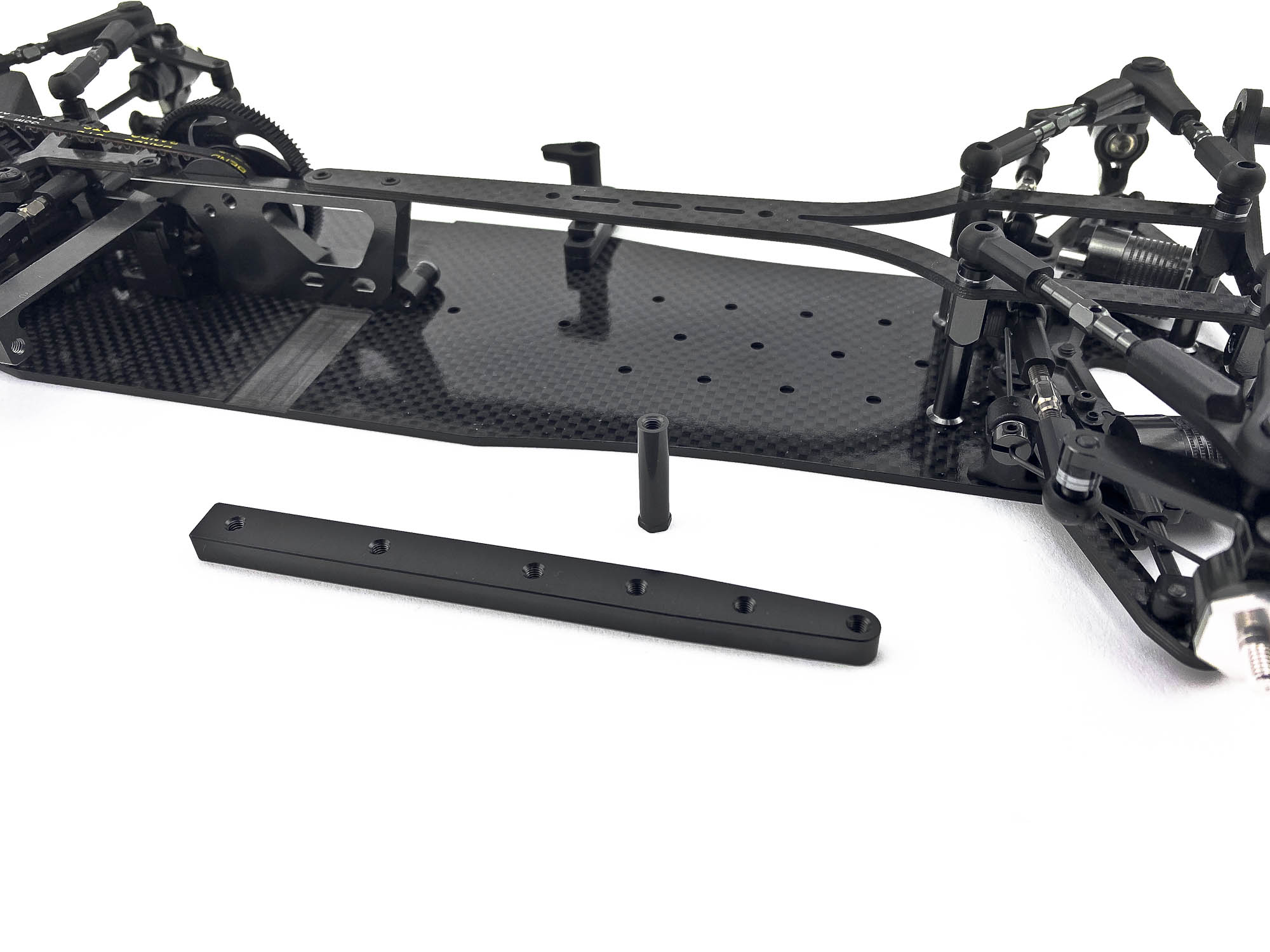
Lets start with a short comparison of the main chassis from the FX and FX Evo. Left side is the "old" FX chassis and right side the new FX Evo chassis.
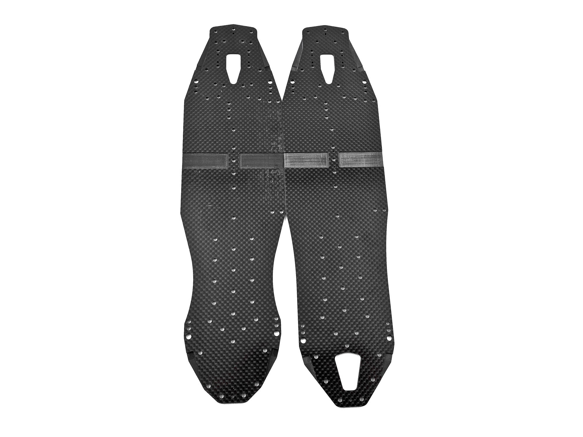
The Evo chassis (lower one) has a noticeable longer rear wheelbase. The rear dampers and suspension arms shifted to achieve this. Bulkheads are at the same position as before which means also topdecks are same for all FX models.
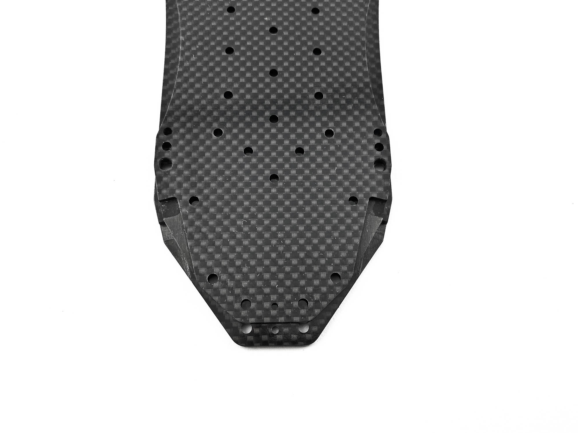
Also the flex of the rear end is changed. The Evo chassis (lower) is more stiff compared to the FX version.
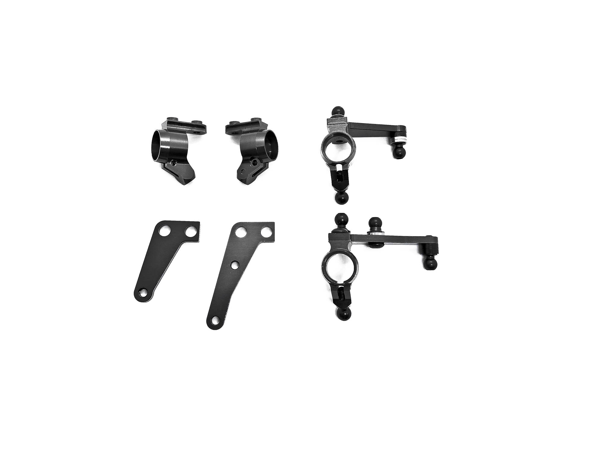
STEP1 is the assembly of the well known wheel hubs. Same as the FX the Evo use the AM14FX steering arms.
SPECIAL TIP: for extra smoothness of all suspension parts you can polish the ball studs with very thin sandpaper (2000 grid) or something similar. In this build I didn't do it and used it as it came from the factory.
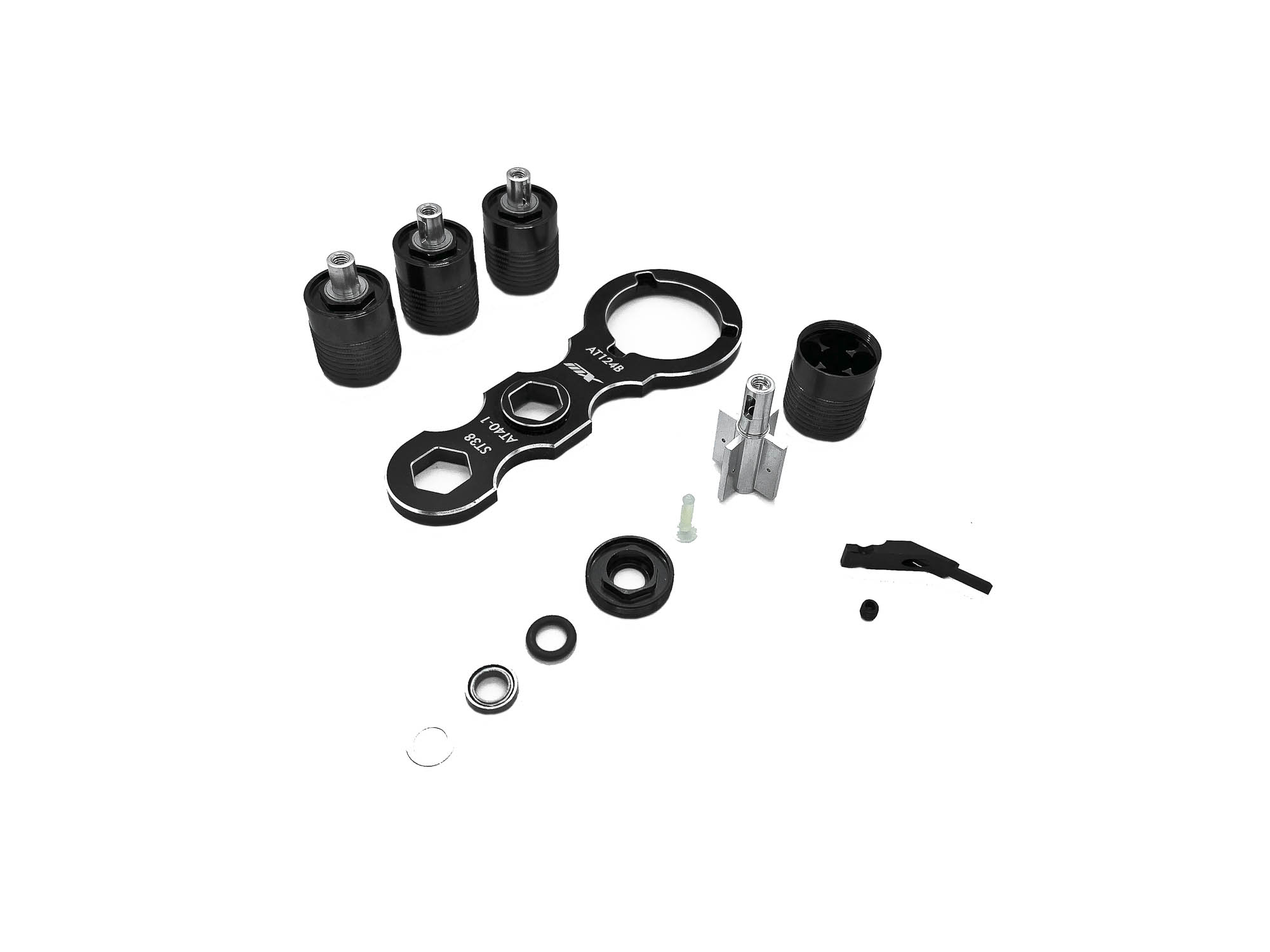
The assembly of the front driveshafts, which use the well known IFJ system, is even more enjoyable with the right tools and fluid. I recommend the MXRL Awesomatix TC Multi Tool, as well as the special mixed Driveshaft & Gears lube!
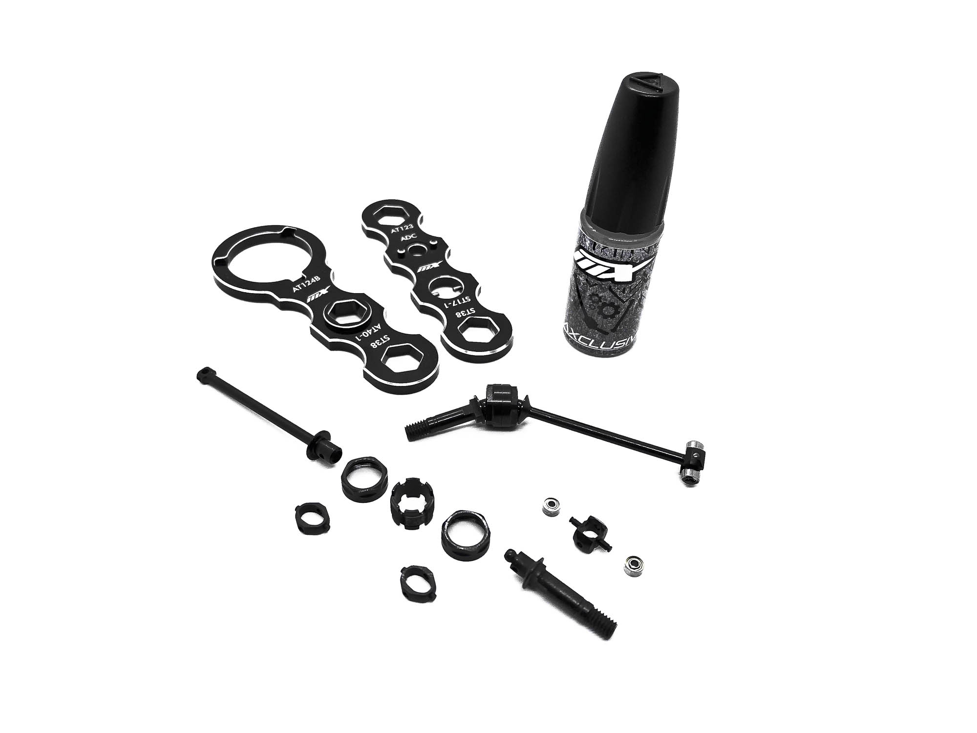
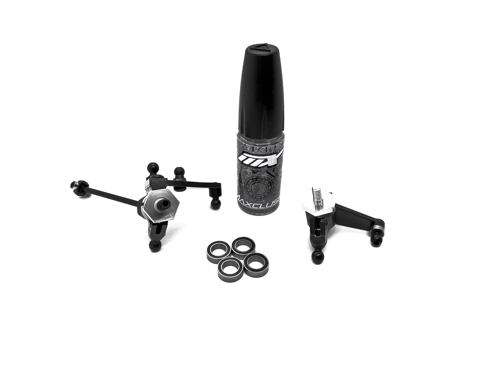
Completing of the hubs with driveshafts as per manual. As option part I can recommend the use of AT15 bearing spacers for the front.
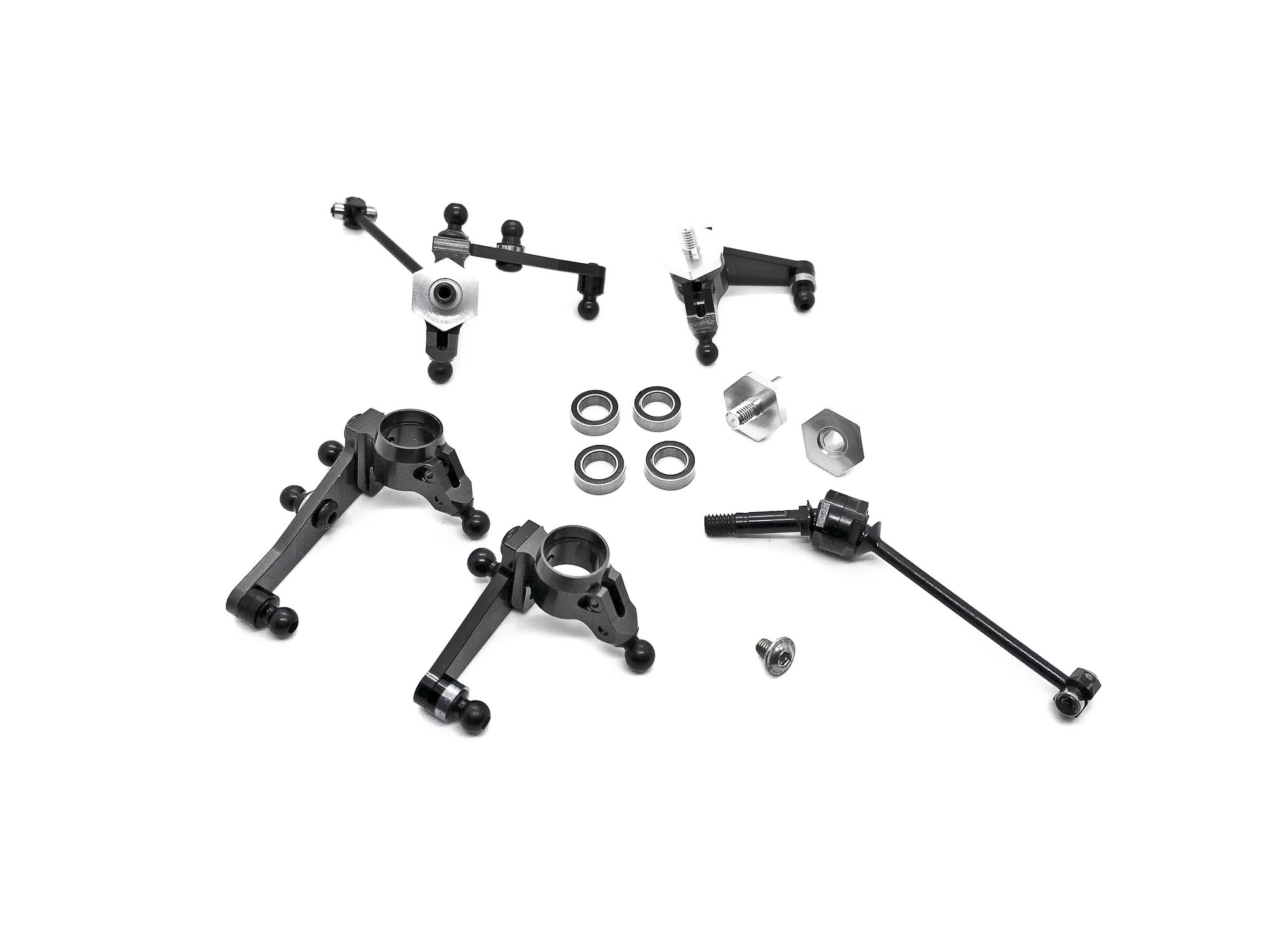
SPECIAL TIP: Use a drop of the MXLR Ball Bearing oil for each bearing to get an extra free and smooth drive train!
|
For STEP4 I recommend to pay attention and not over tight the SB25X8 screws. Make sure the wheel hub is able to move very smooth and free! Also take care to choose the right arms for front and rear wheel hubs. Front needs the longer C04M1+9.0 arms and rear the shorter C04M1+8.0 arms.
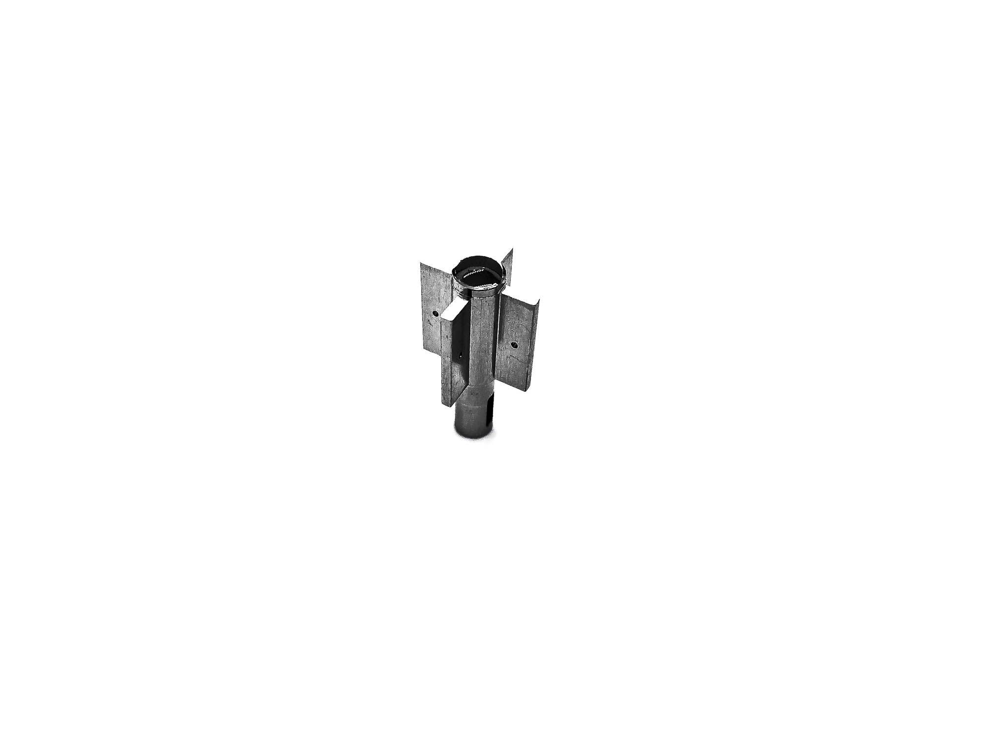
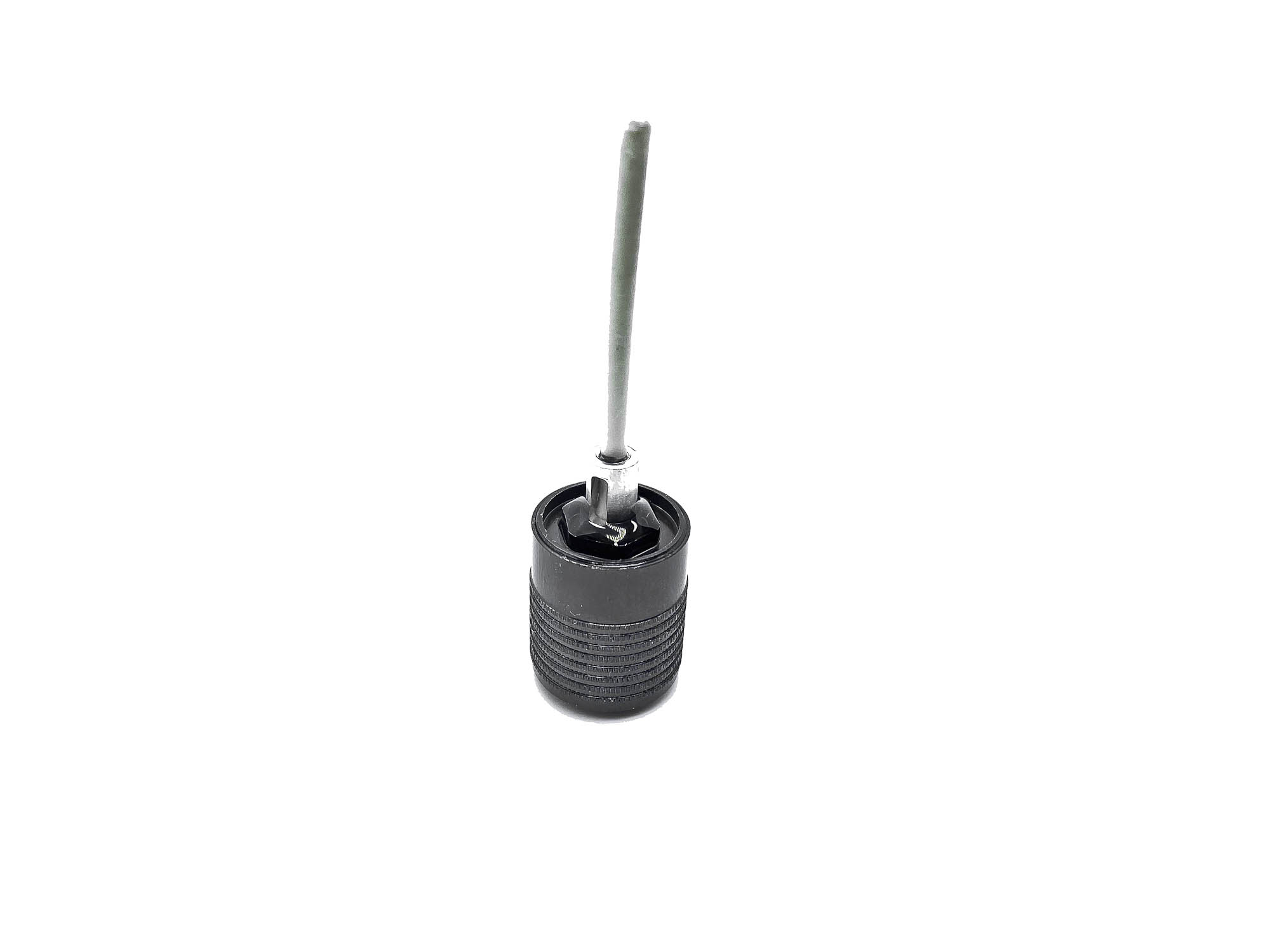
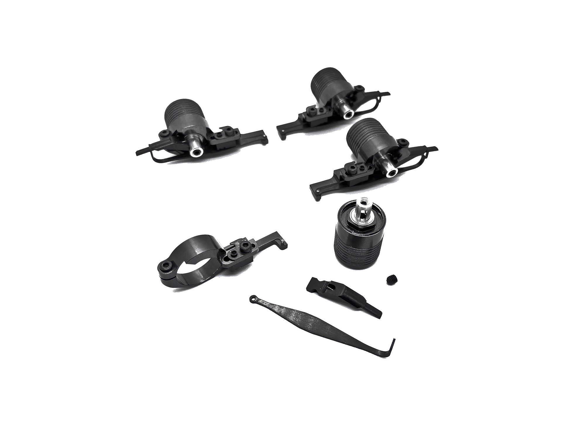
Fifth step is my favorite one. The assembly of the D2.2-S-P Dampers. Includes in the Evo is the latest version with P63 pistons!
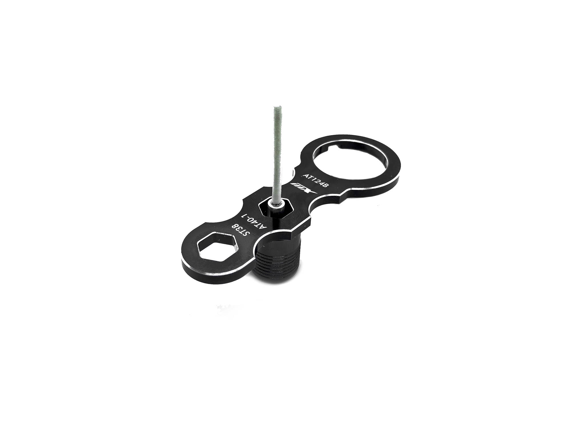
Highly recommended again at this step --> MXLR Awesomatix TC Multi Tool for easy assembling.
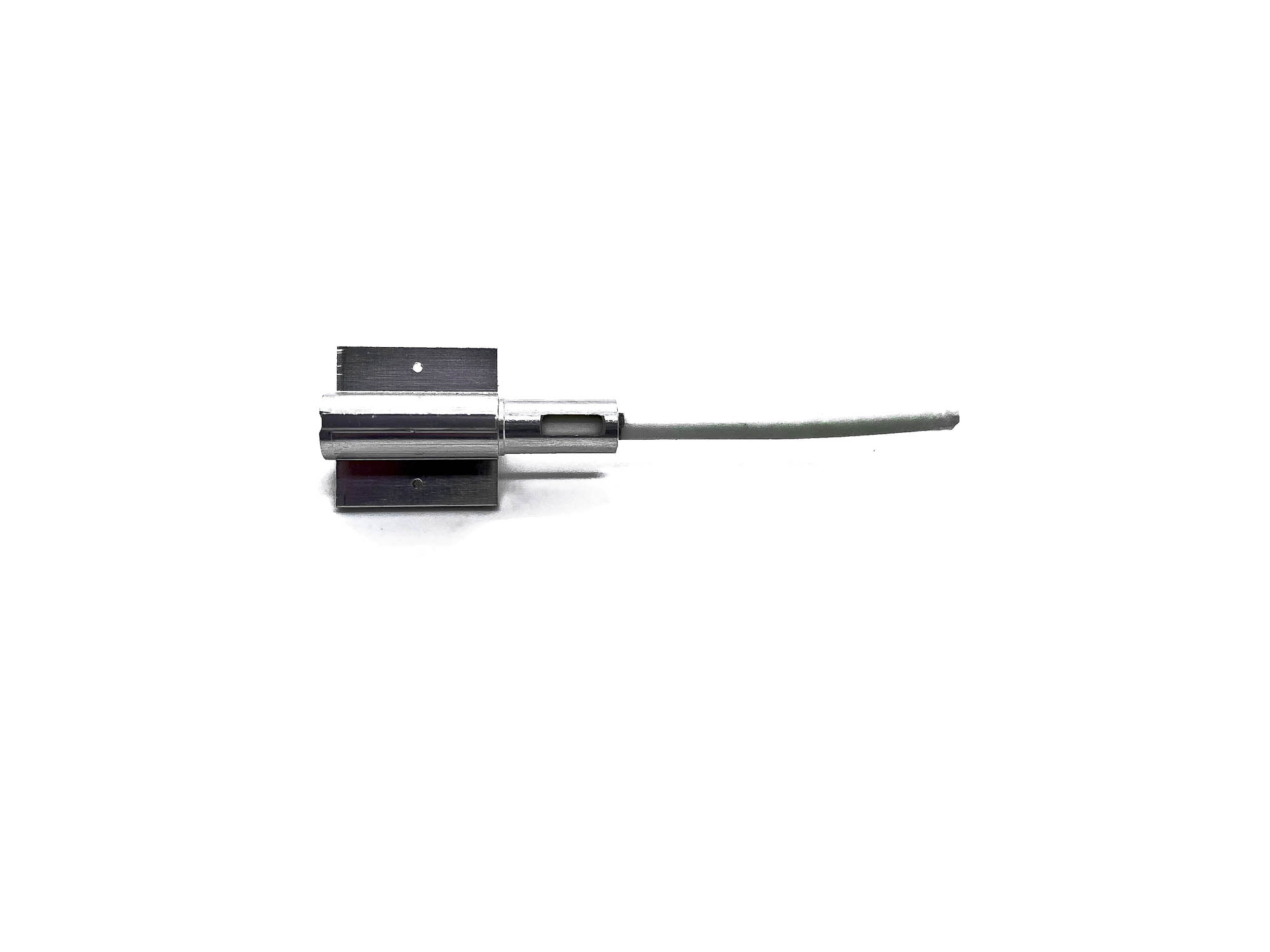
Different from the instructions I recommend a different placement for P63. The shaft of a q-tip has the perfect OD to fit as a "dip stick".
Mark 12,5mm here and enter it from top side into the rotor.
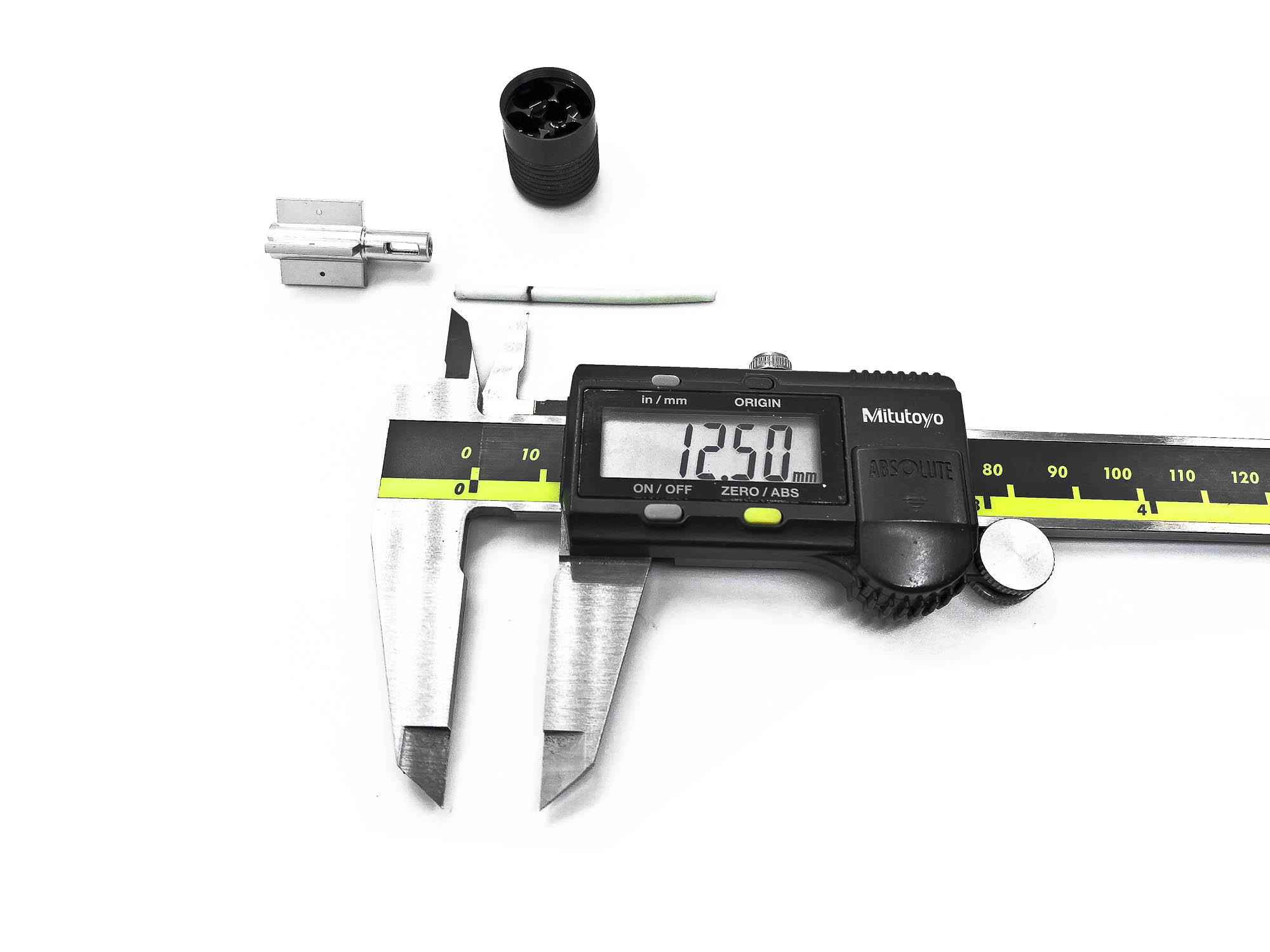
With the dip stick pushed in 12,5mm - enter the P63 from the lower side and push it up till it stops.
Before you enter the rotor into the case, fill the lower cavity with the same silicone oil as the housing itself.
Fill the housing and let the rotor sink down. I recommend AXON 37,5WT (450cst) as initial start point. Turn the rotor 2-3 times from end point to end point and let it sit for some minutes. Alternatively you can use a vacuum pump/case to remove air bubbles.
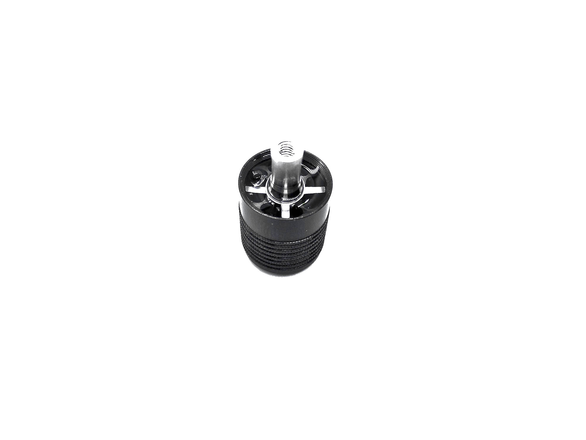
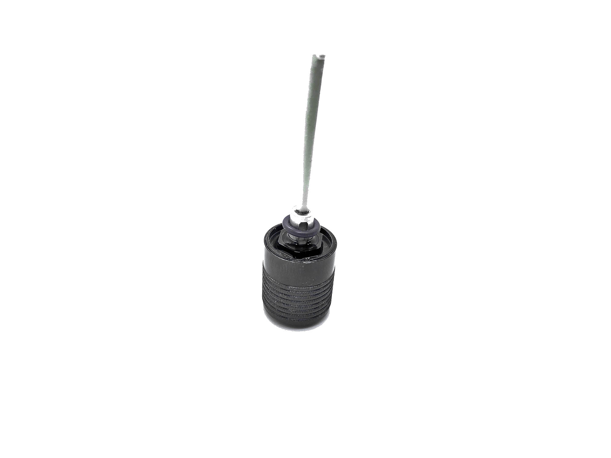
Enter the dip stick again into the rotor till the 12,5mm line before you close the damper cap!
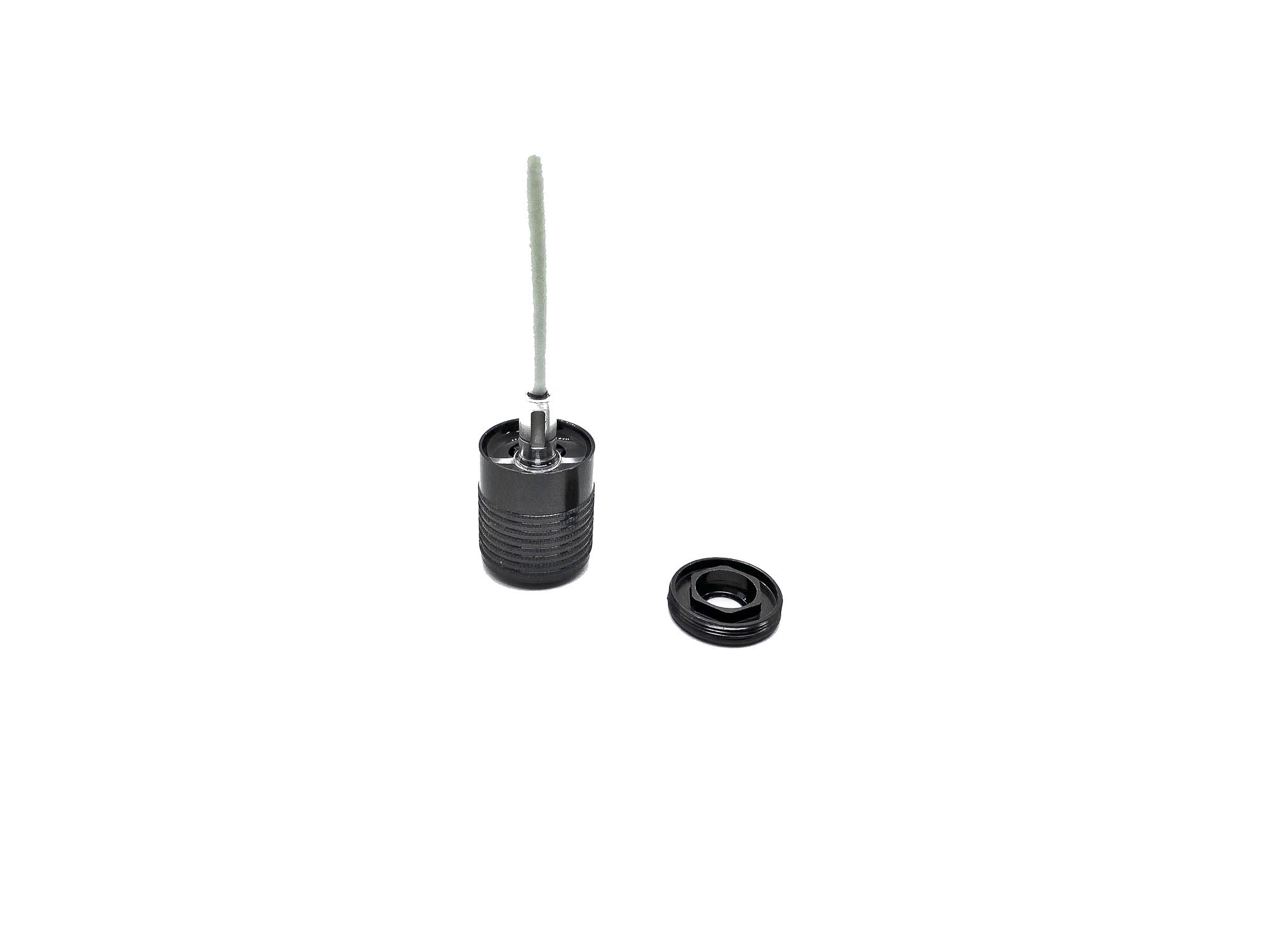
Screw down the damper cap fully!
The dip stick will ensure to keep P63 at desirable position and additionally close the top side holes of the rotor. Make sure to use proper tools which allow the excessive oil to flow out at screwing! Otherwise you may fail to close the damper correctly.
Let the damper sit for another minute after you screwed the cap with installed dip stick. Some more oil (excessive oil) will bleed out.
Remove a bit oil (not all!) before you install the OR155V O-ring. Keep the dip stick still in place.
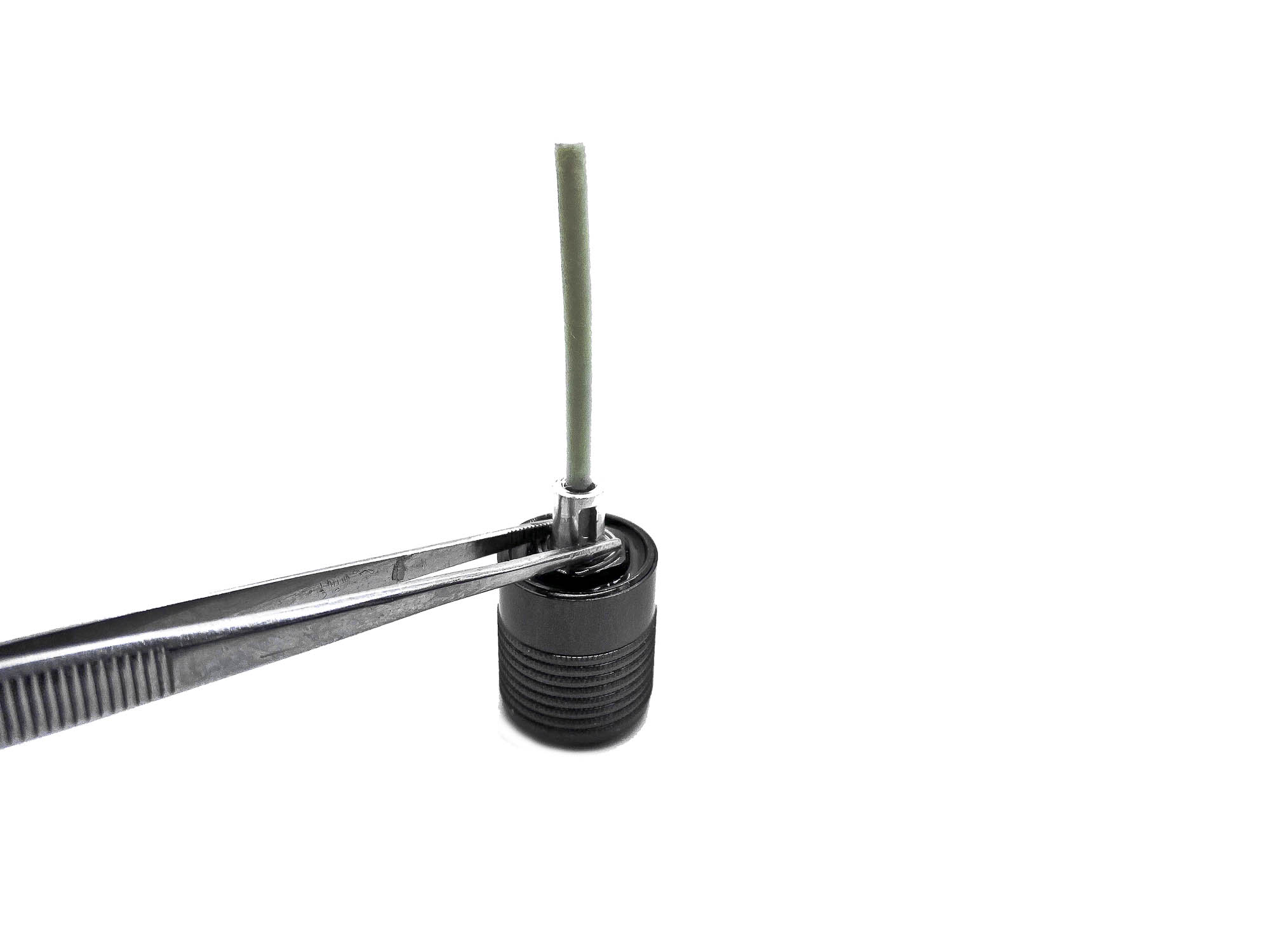
Last step, is the installation of the B85 bearing. I like to use metal tweezers to help pressing it in place. After this you can remove the dip stick and clean the damper to remove the silicone oil on outer surfaces.
AT119 Alloy spring screw holders and ST69-00 linear spring screws are another upgrade in the Evo kit compared to the previous model!
Install the Dampers into the holders. Make sure to set the up travel correctly before you tight the AM17X clamping! As hard springs all around were the favorite at most events, the Evo use them on all 4 corners.
AT21ST-A balls are the next upgrade/difference. They are made from steel to lower the CG and increase the reliability. NOTE they are 0,5mm lower as the old alloy AT21.
Press the P03 arm ball cap on the AT21ST-A. I recommend to use your big thumb for the pressing. By using any hard tool to press it, there is a high chance you break the P03 part!
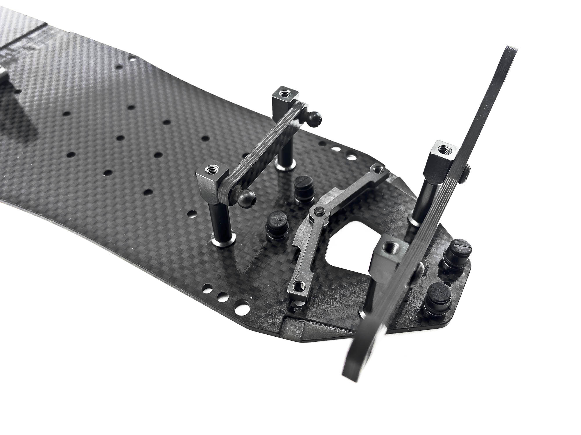
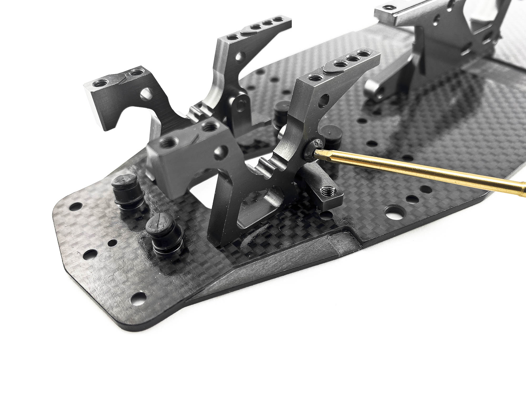
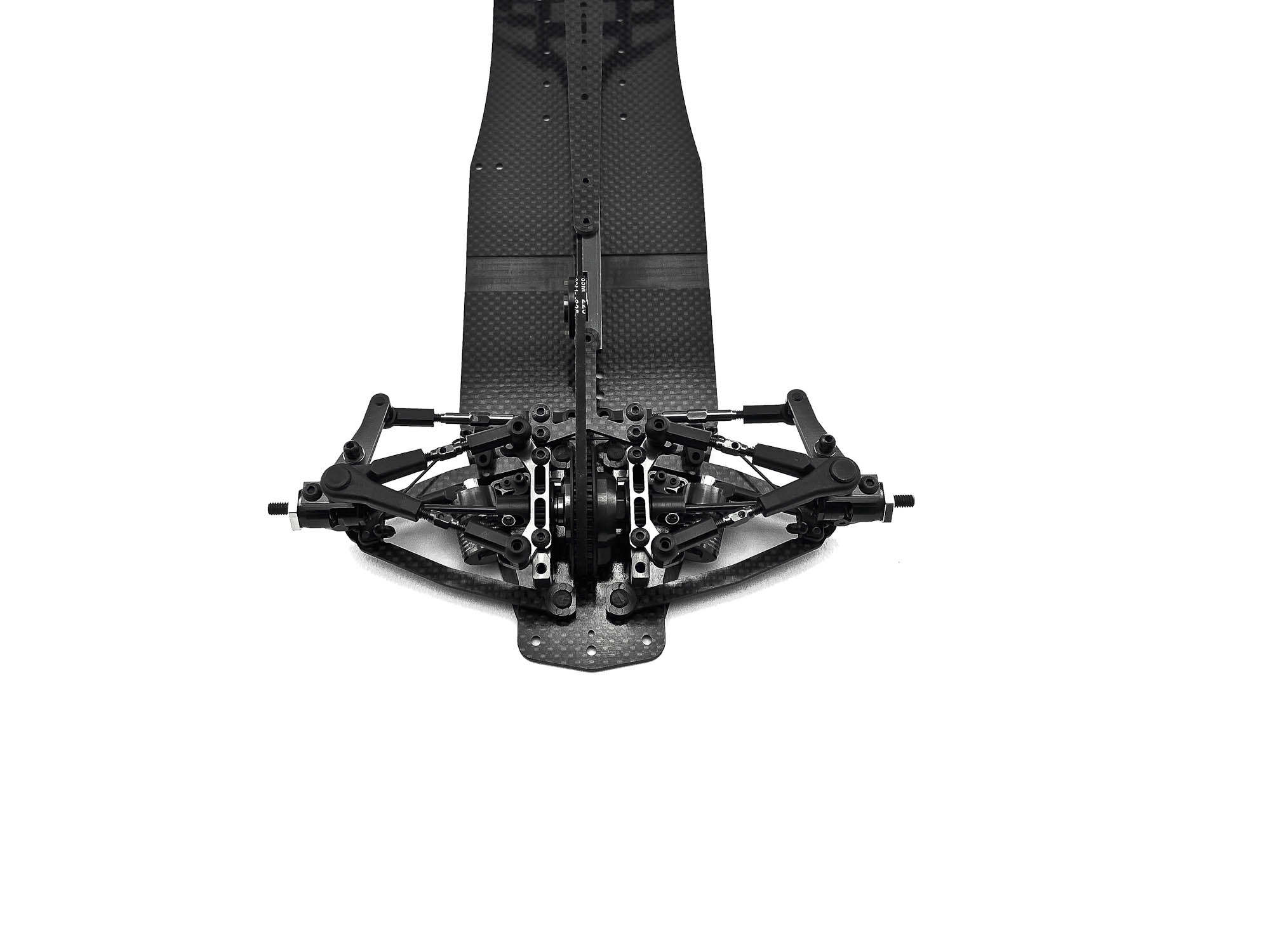
The new AM78FX Bulkheads are an overworked/modified AM78X-1 bulkhead. You can see the silver milled out area. Its needed to give enough room for the new bell crank steering.
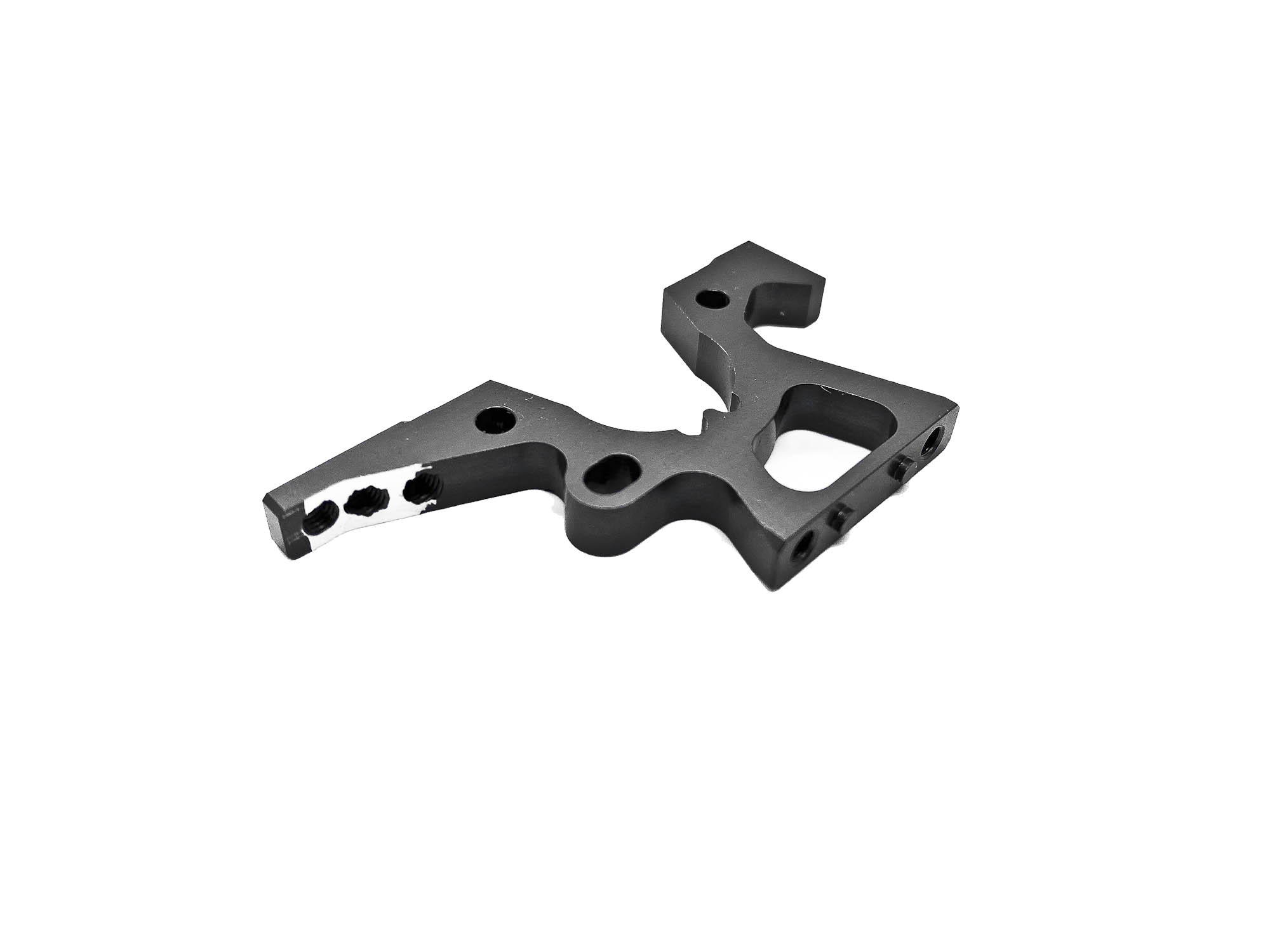
Screw all bulkheads and the motor mount to the chassis as shown in the manual.
Take care to follow the info about the tightening sequence for the rear uprights. Otherwise you will note excessive tweak!
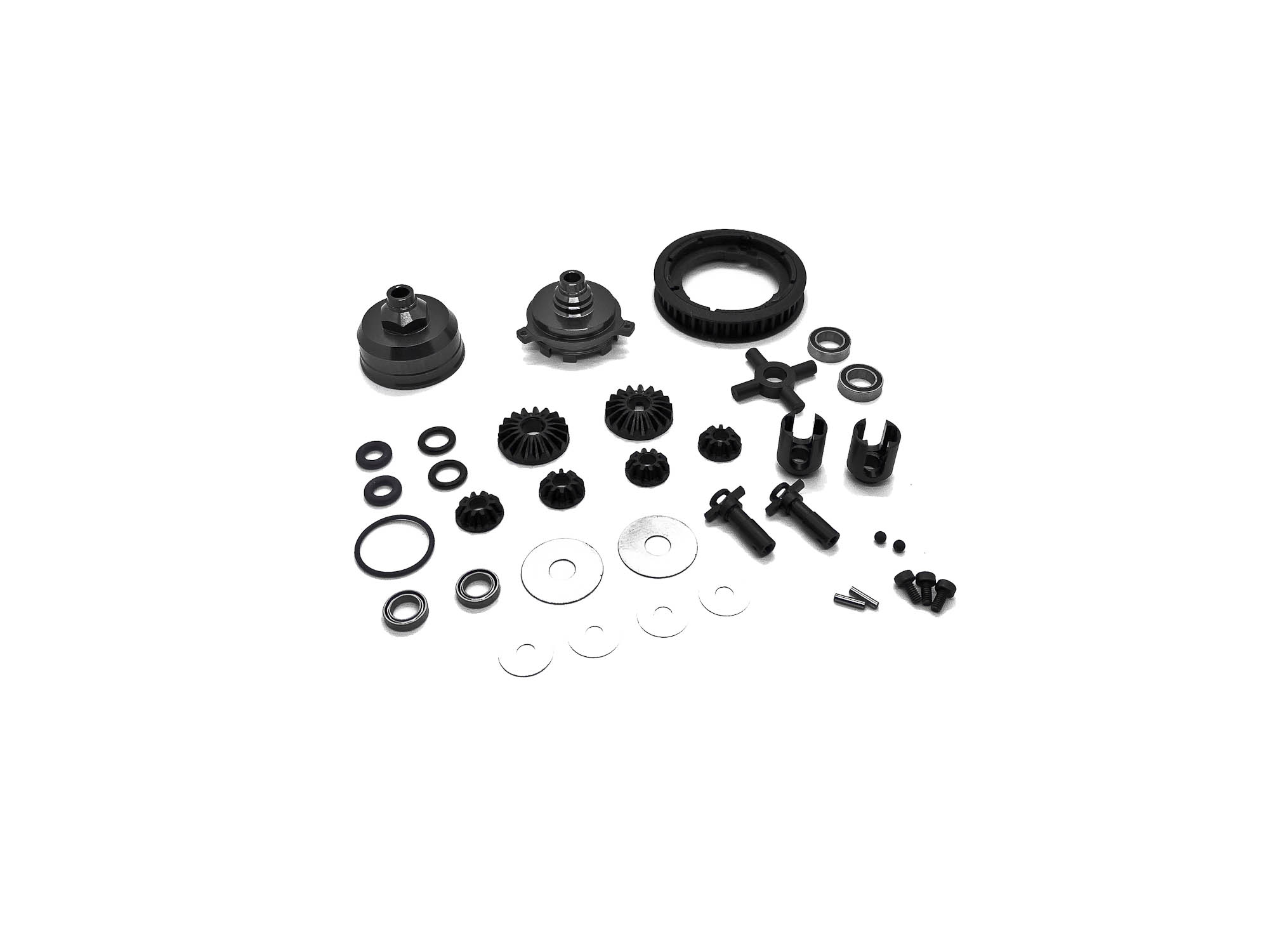
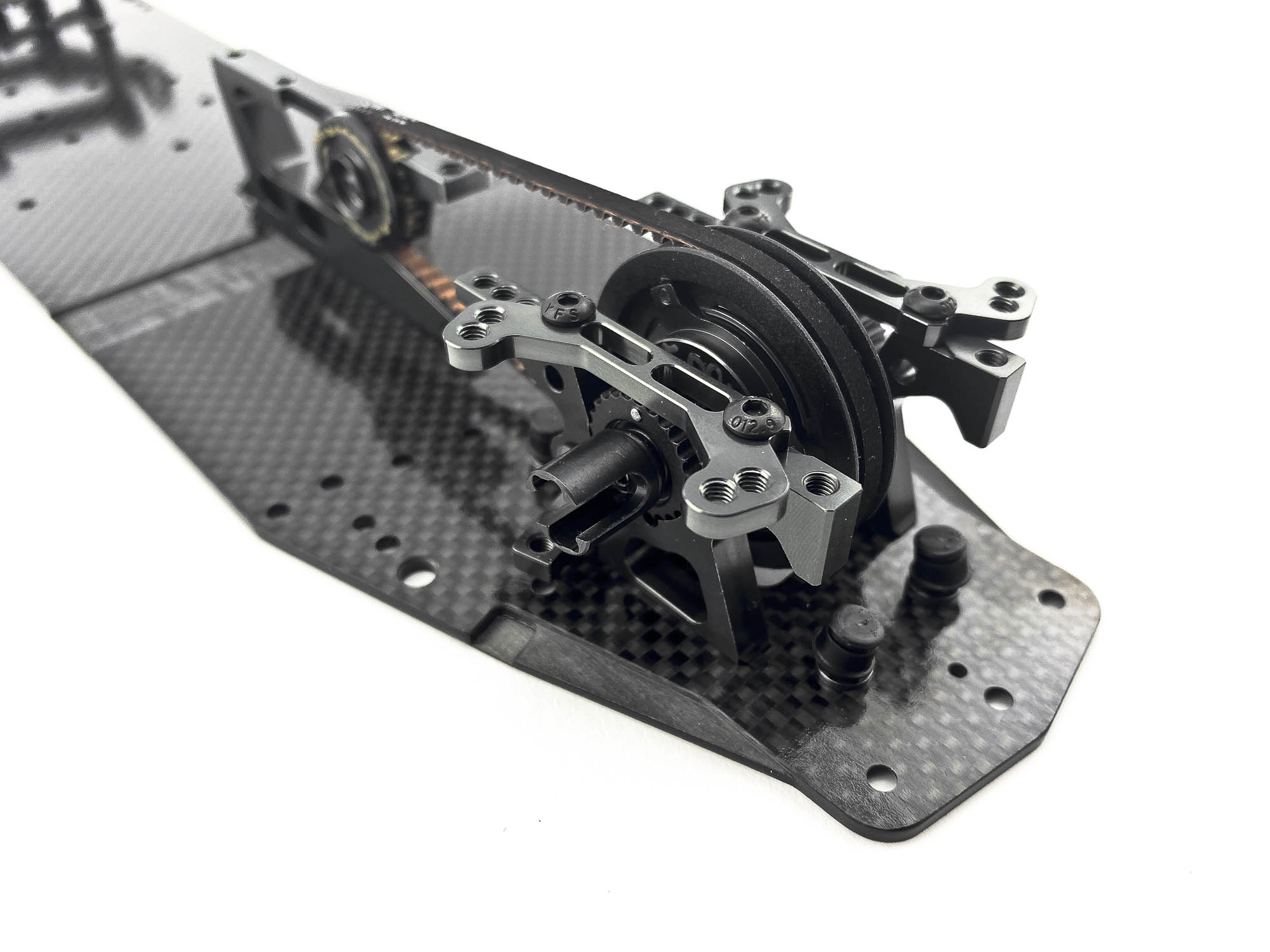
GD2B-R is unchanged. Reliable and good performance as well as smooth operating. Take your time to build it with the hard/stiff oil! It will need some minutes to "flow" in place
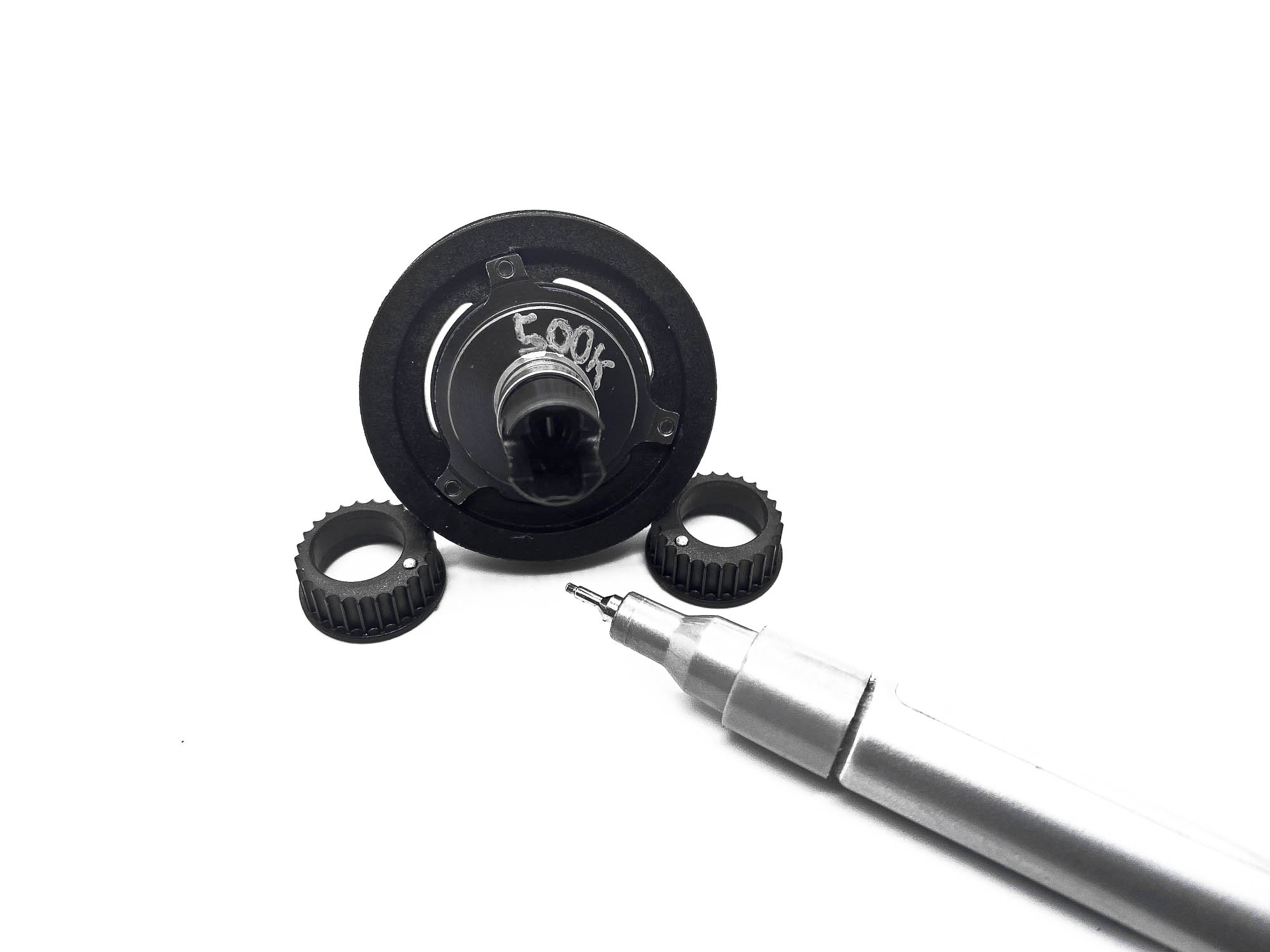
I recommend 500.000cst Silicone oil as initial setting. With a silver pen I put a note on the differential case to remind whats inside and also mark the P110 dot's for better visibility when setting belt tension.
Screw the rear AM08FX shock holder with the correct amount of shims as per manual with the middle screw. But don't tight it fully at this stage!
Same for the front AM88 Shock Holders. Don't tight the screws fully at this stage. We will do it later when we slide in the shocks.
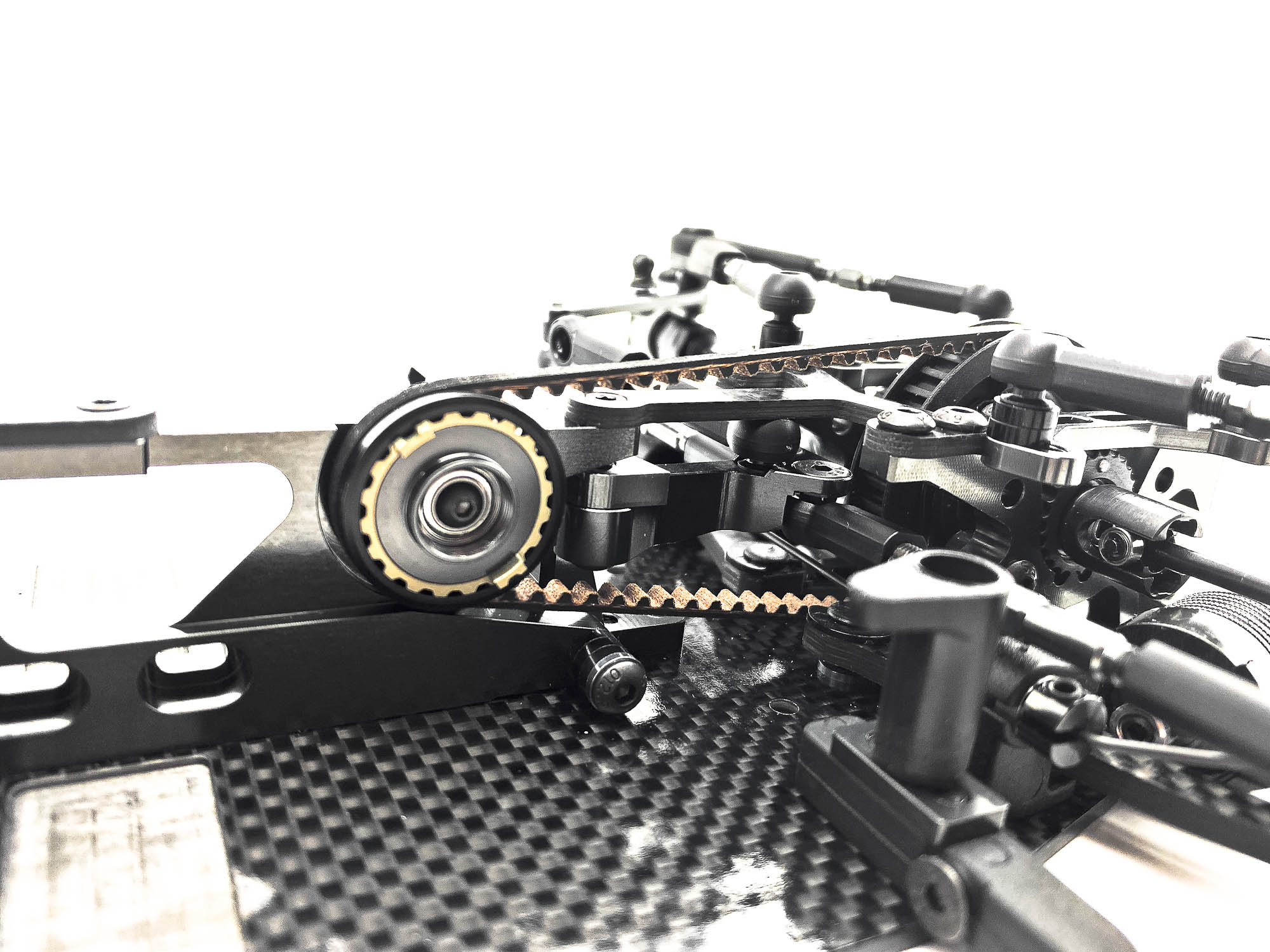
Make sure to install the belt together with the middle pulley. It's not possible to press the belt from the side or "turn it over the pulley" without damage of the belt!
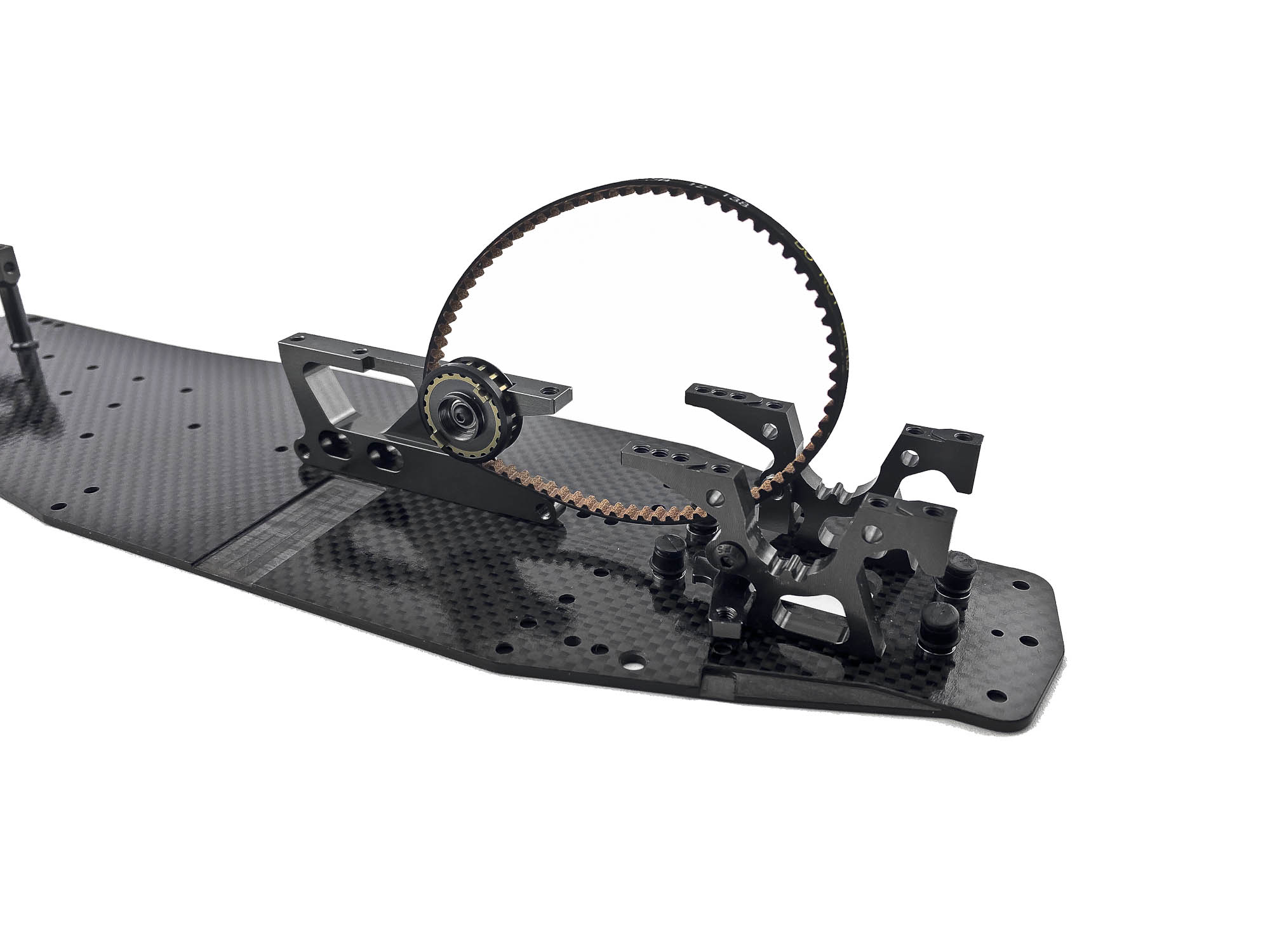
Put in the diff with P110 excenters and set the belt tension same left and right before you screw the AM19-FX upper arm holders.
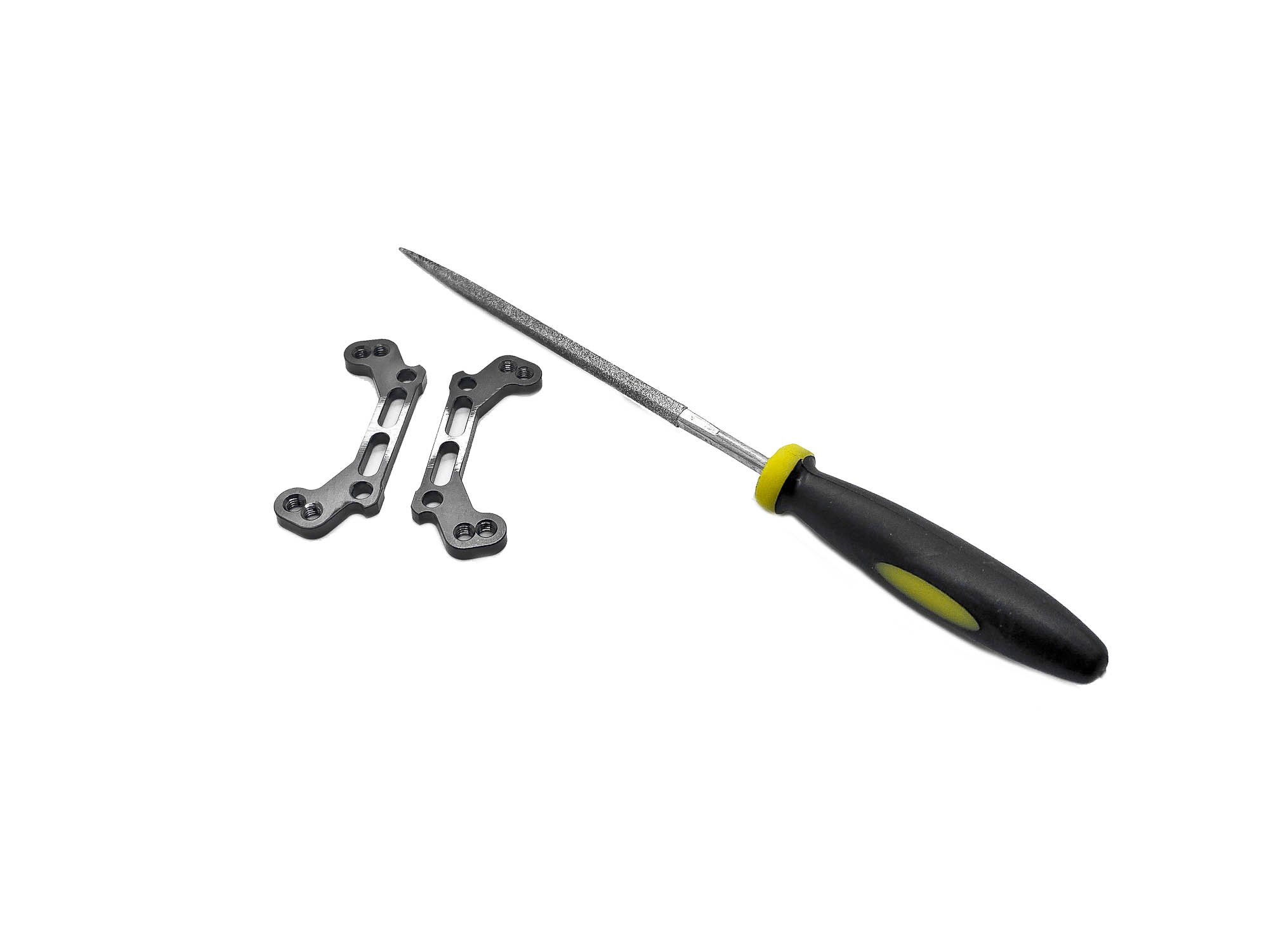
SPECIAL TIP: The diff should have some free play to left and right side when the upper arm holders are installed. I like to use a diamond file and slightly remove some material on the lower side of the AM19-FX to free up the diff clamping. Take care and don't remove to much! Up and down play is not wanted and would be a disadvantage!
|
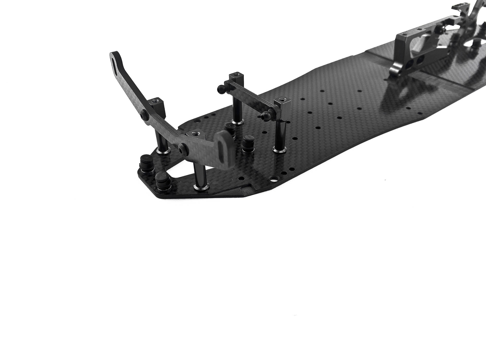
Both, front and rear topdecks are overworked and got a new design. They also fit the "old" A800FX in case you want to upgrade.
The C107S front topdeck offers more flex as the previous C107. Additionally its possible to increase the flex even more by using the ST09 steel collars in the rear holes.
Take care about the correct orientation of the topdeck. The ST019 screw hole has a recess on the topside.
On the rear C27FX-2 are no recess areas for the ST019 screws! Make sure to have the chassis on a flat surface when you tight the screws to avoid unwanted tweak.
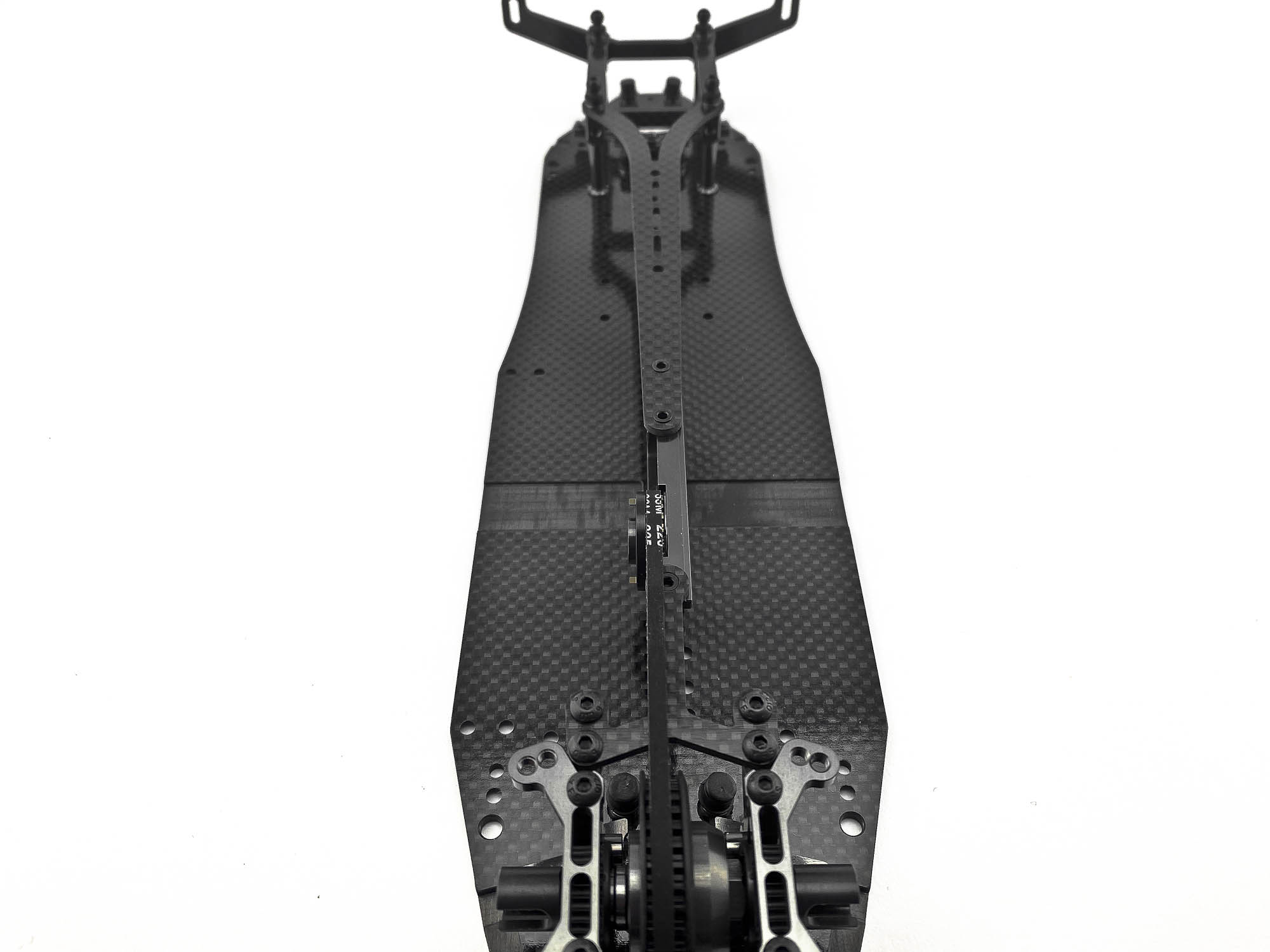
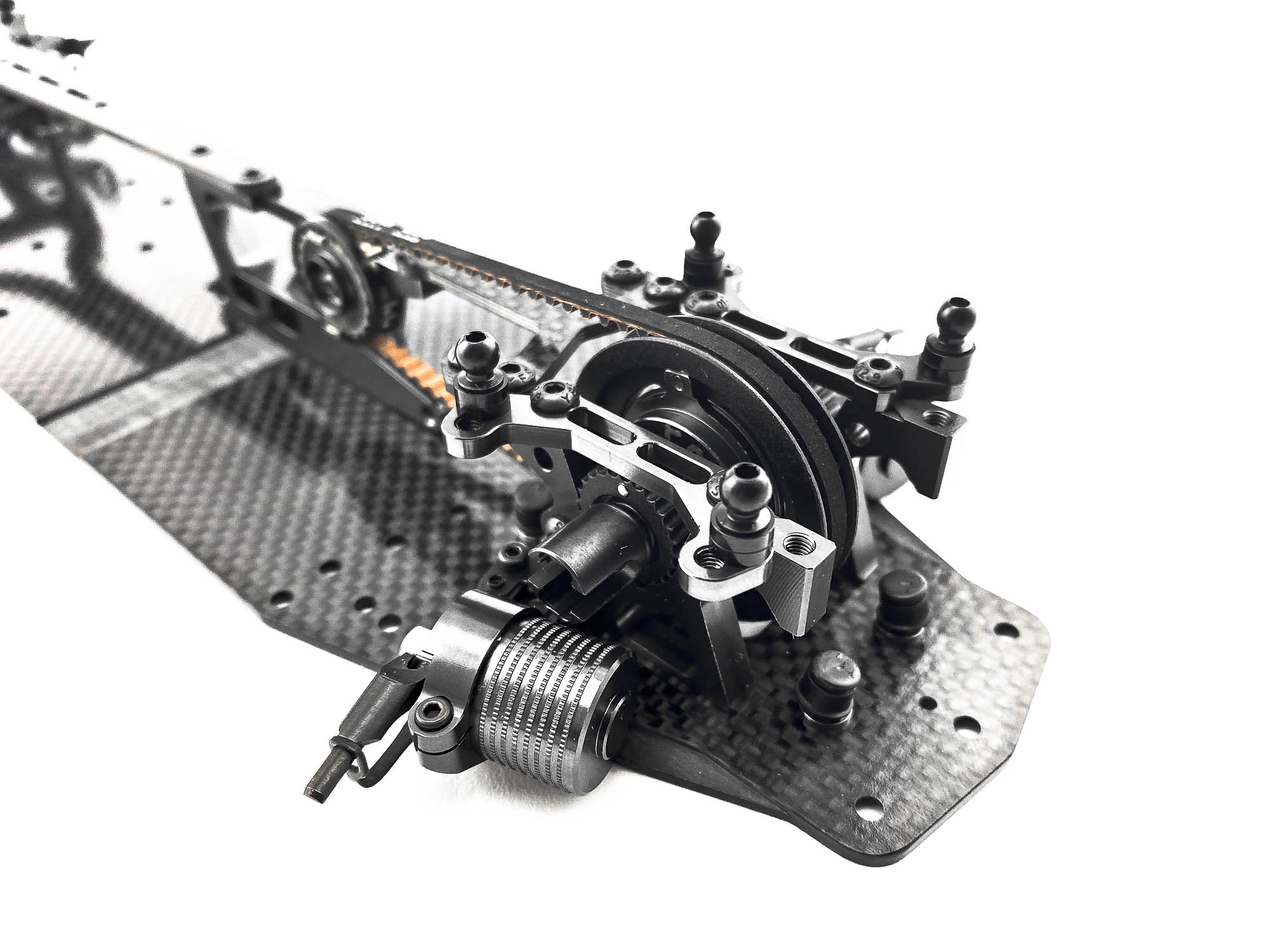
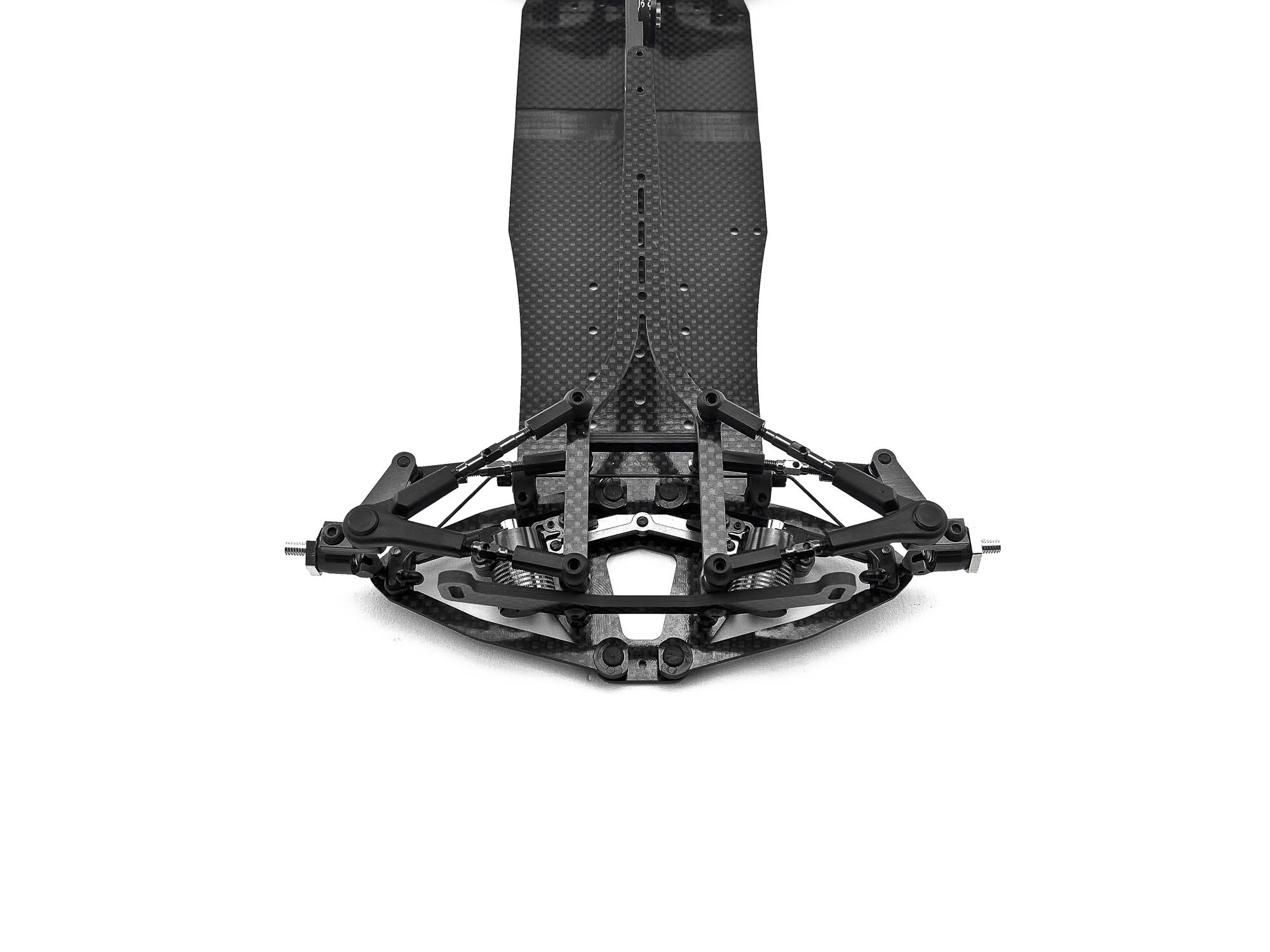
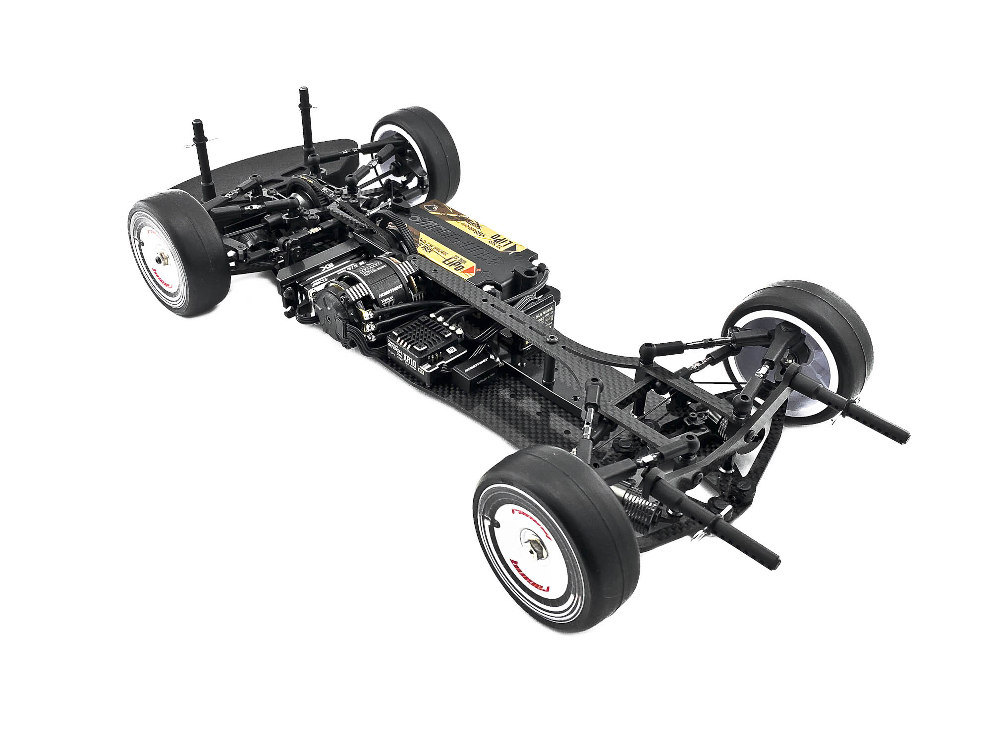
Look at this super slim center line! What a beauty of a RC Car
Slide in the front shocks fully. Now you first tight the SF3X10 screws from the lower side, and the SB3X8 on the bulkhead just after! Now AM88 is set correctly.
Similar at the rear end of the chassis.
Slide in both shocks fully till block and enter all screws. Tight them first when all is aligned.
Short overview after STEP 16. Hope you enjoy the build so far!
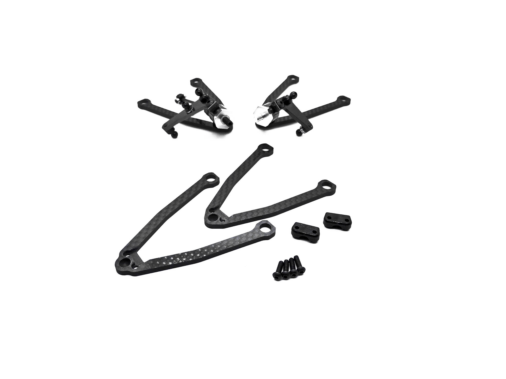
Screw the front upper link ball studs. Also here you can use (like for all other ball studs) my earlier mentioned tip about polishing to create extra smoothness.
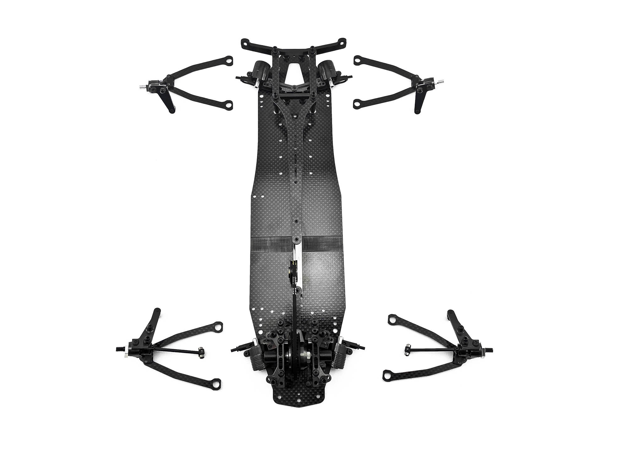
Merging of suspension and chassis frame. Take care to install the right arms in the right spot.
Push the P07 Arm clip into P03 to secure the arms on the chassis. Optional I can recommend the OR14V suspension arm o-rings!
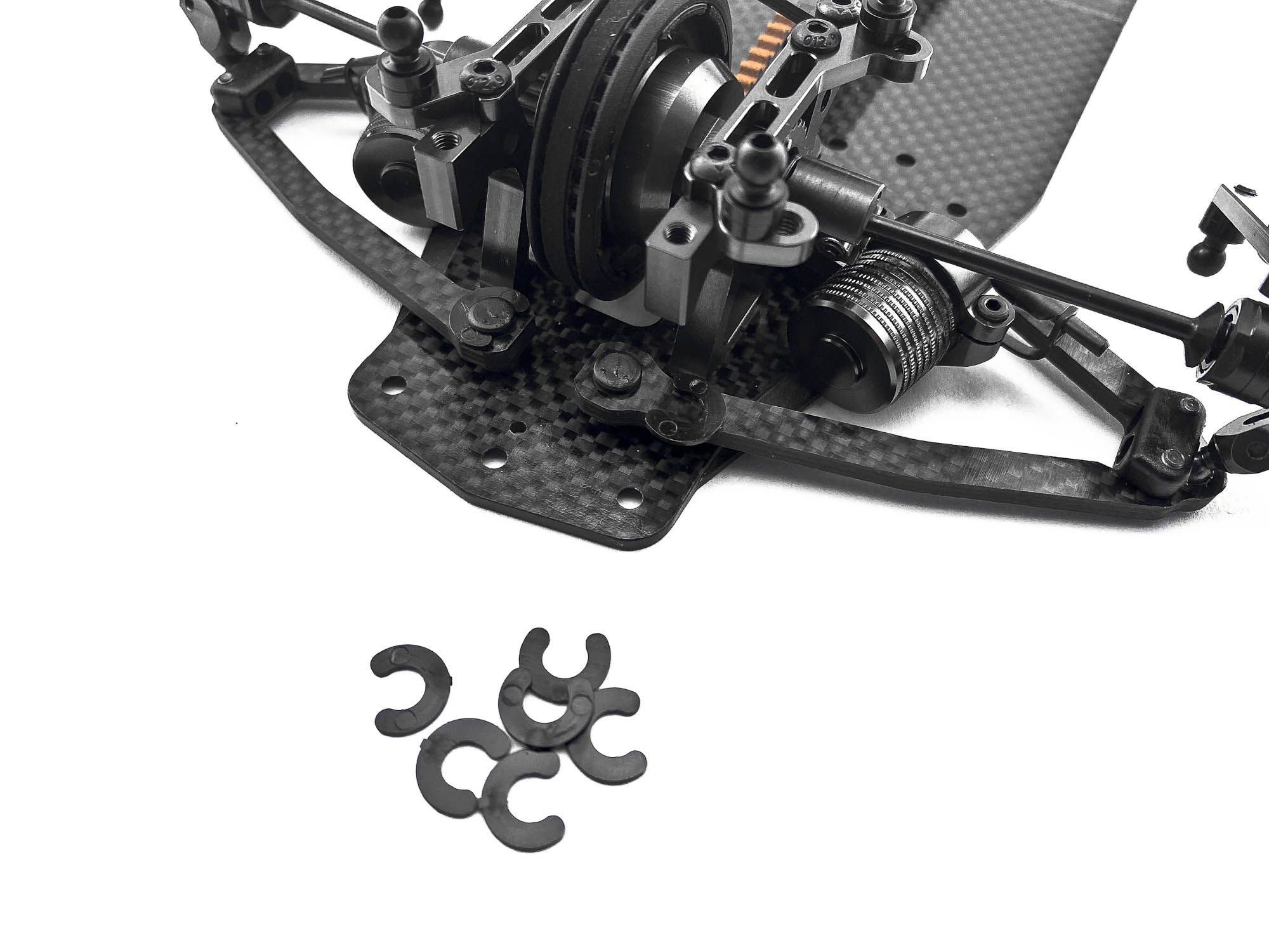
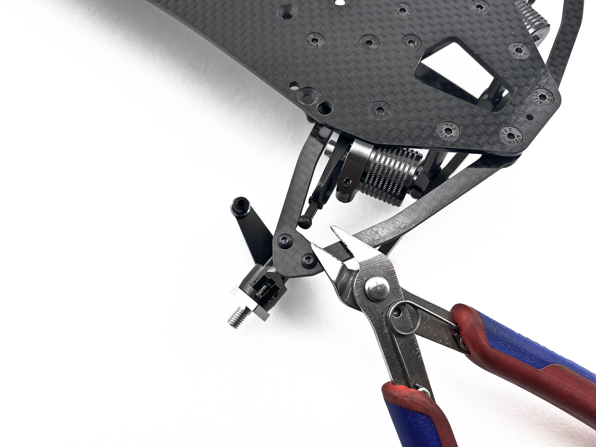
Snapping of the ST05L can be hard in case you are not used to it from earlier models. This connection needs to be very strong, so it needs a lot of force for installation. I recommend to use sharp side cutters for the pressing and also the unsnapping at later rebuilds.
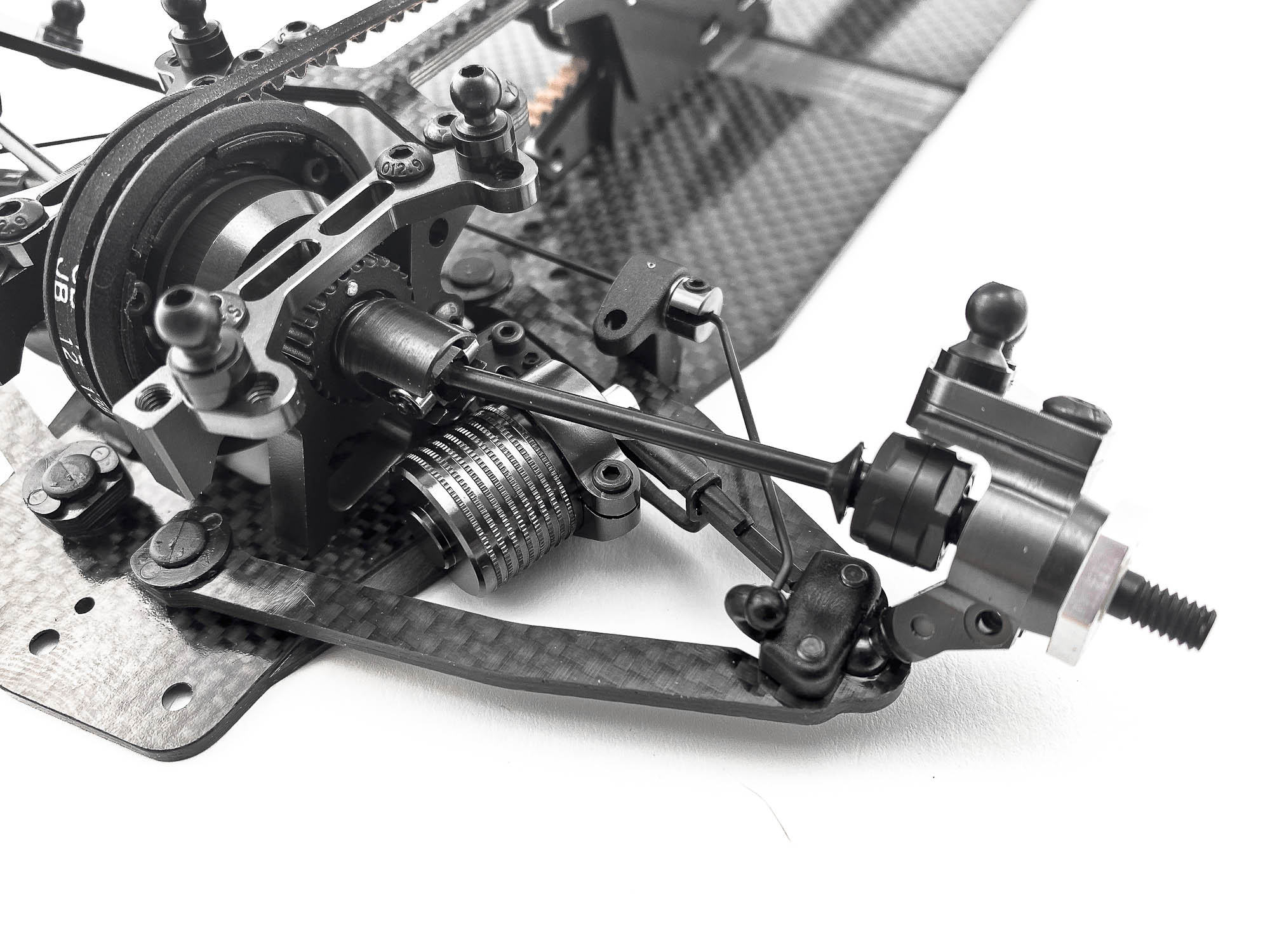
Next up is the installation of the sway bars. Screw the P12X to the chassis and enter the grub screws for the down stop setting from the lower side.
Add a drop of ball bearing oil to the B63SS for extra smooth operation!
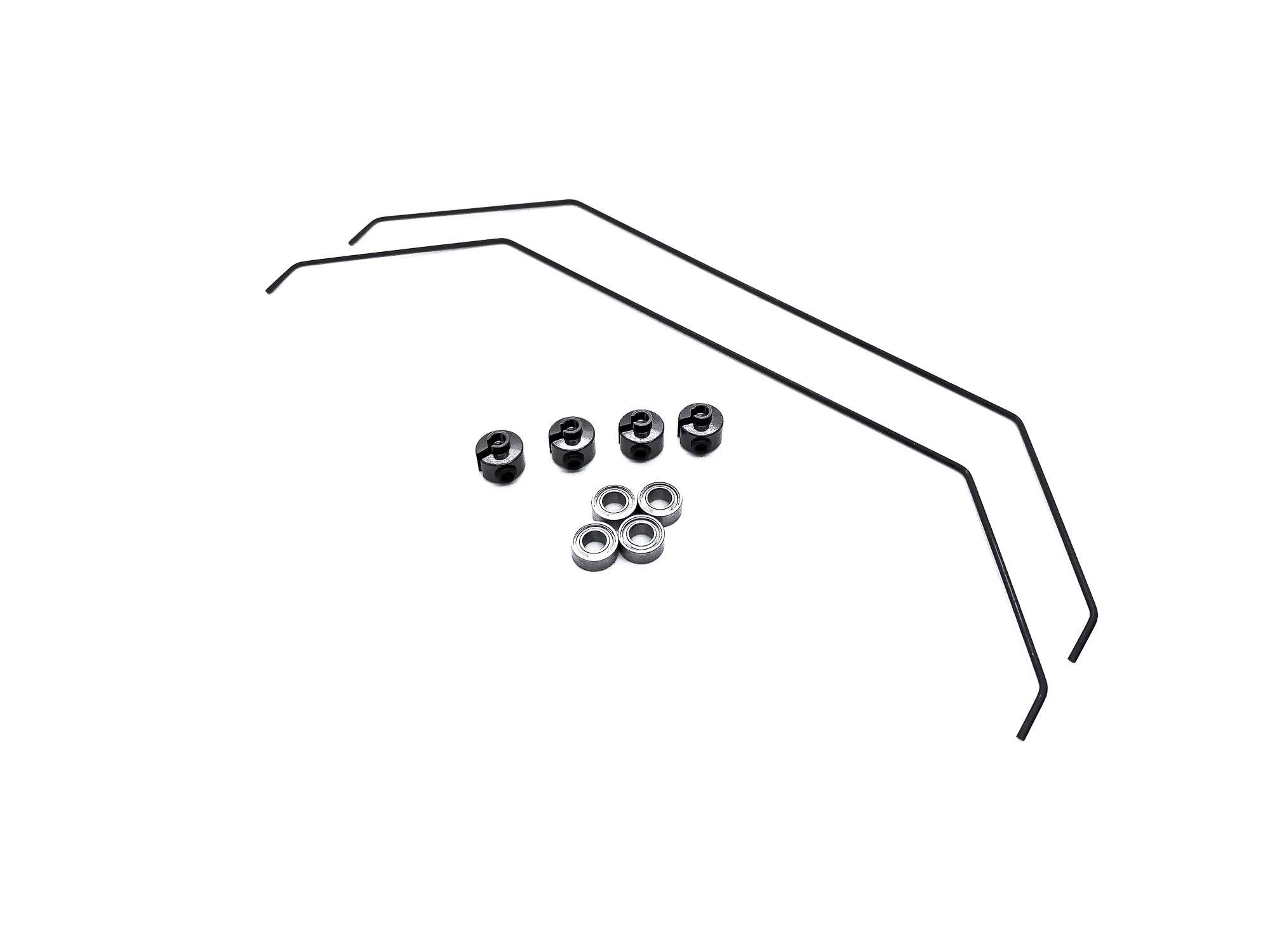
Take care to choose the right side of P05 for the connection of the sway bar to the arm. One hole is bigger for 1,2mm sway bar, and one hole is smaller for 1,1mm and 1,0mm sway bar.
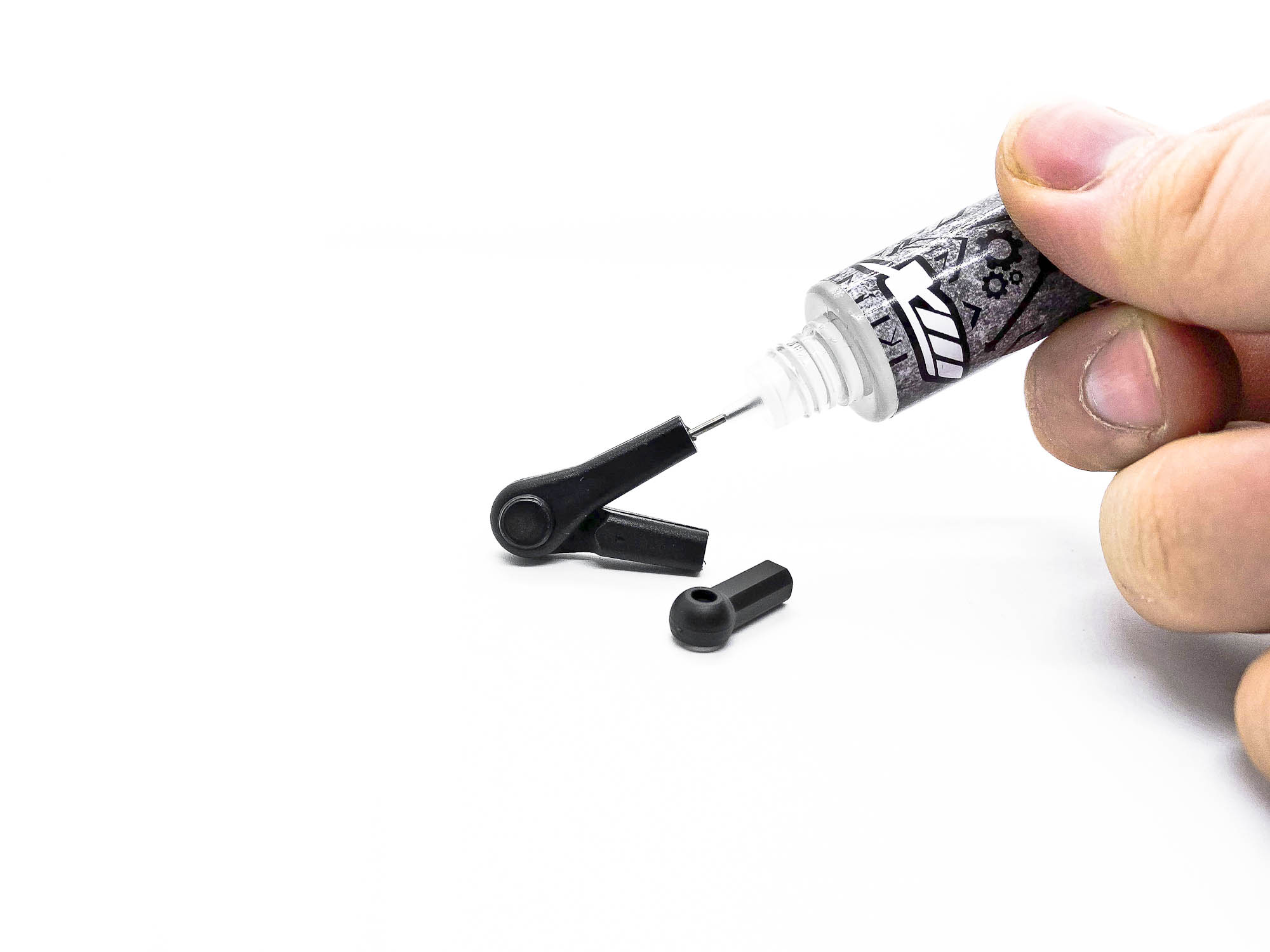
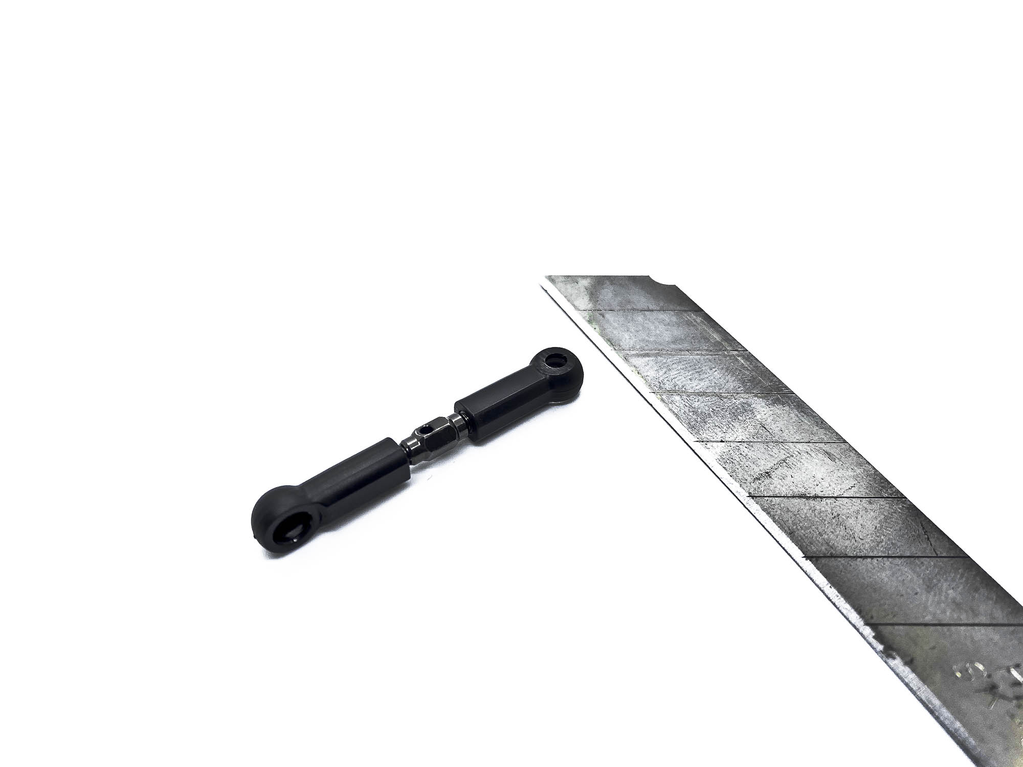
Building the turnbuckles is my least favorite part of the whole build. BUT with my MXLR Driveshaft & Gears oil its a lot more enjoyable than ever before!
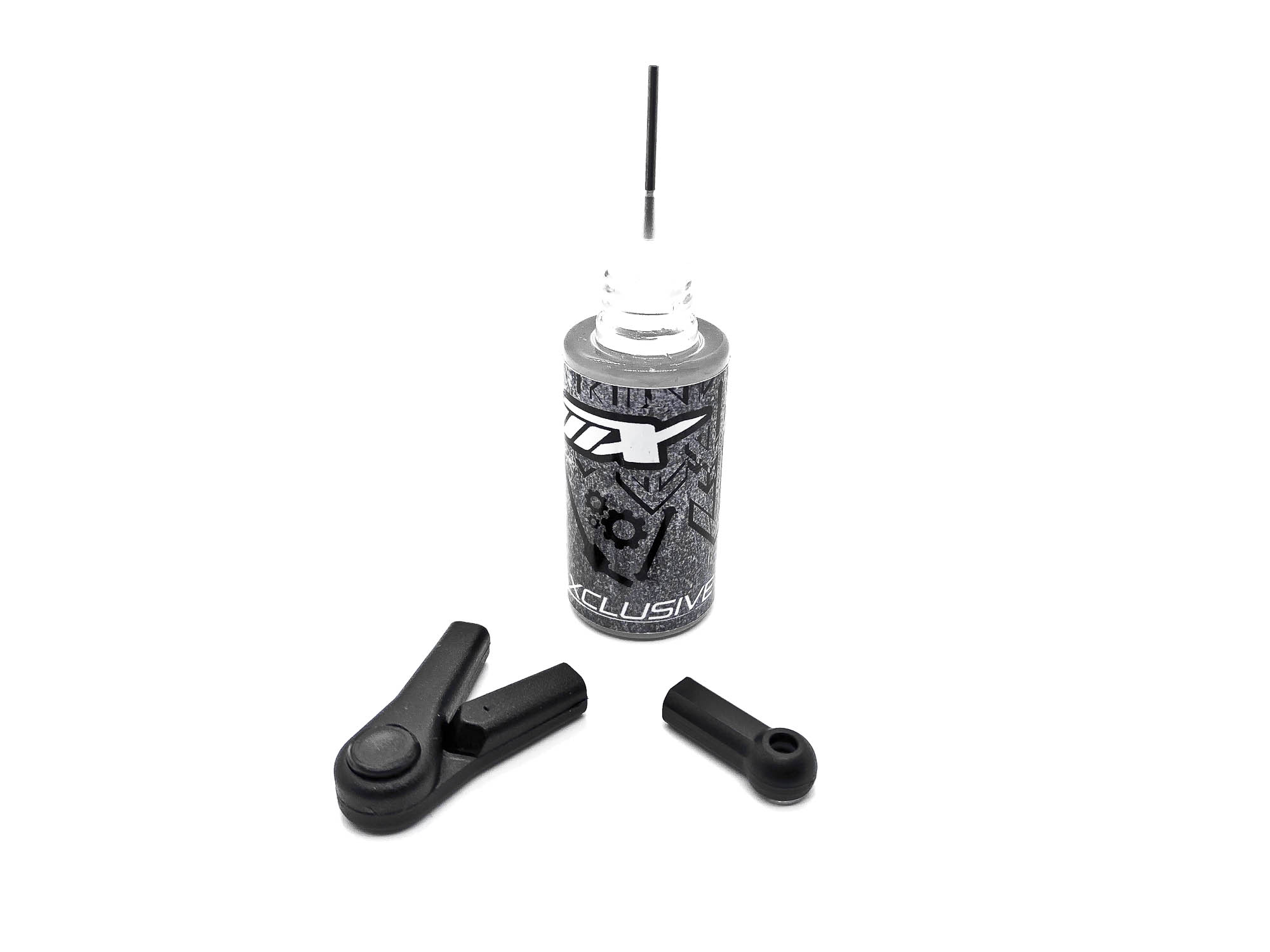
Just add a drop into every P01/P02/P13-4 before you screw in the turnbuckles. It will make the process and turning a lot smoother, not only during the build, also later at track when setting the car.
DONE! I like to have the hole (left-hand thread) always facing outwards to the wheels. But everyone has his own preferences here.
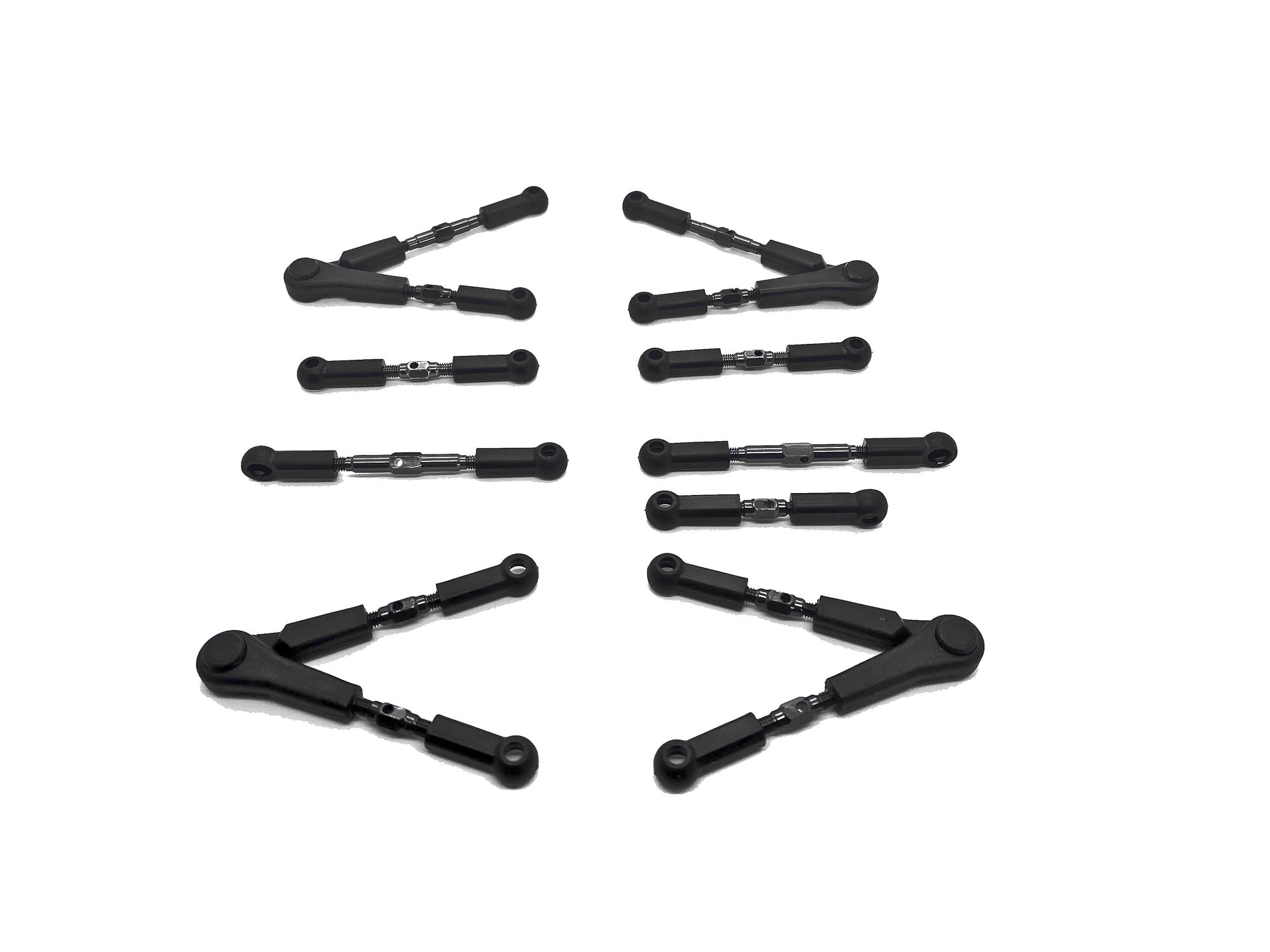
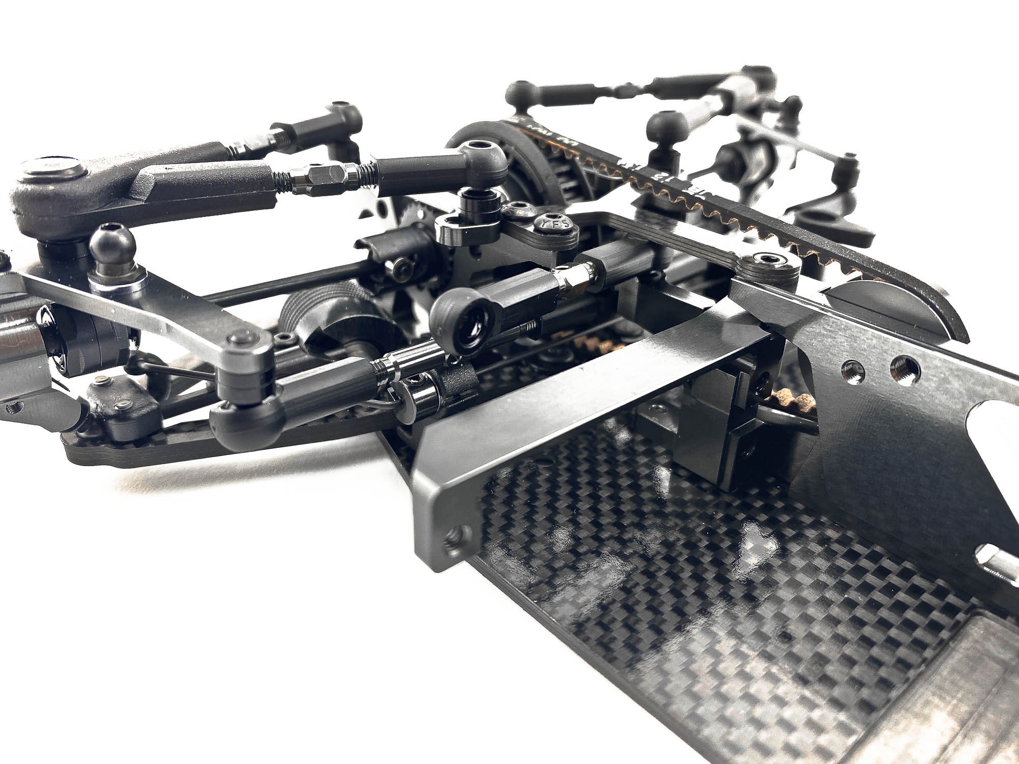
Install all the links at the right corners. Especially take care at the rear links to put the long turnbuckle at the right side
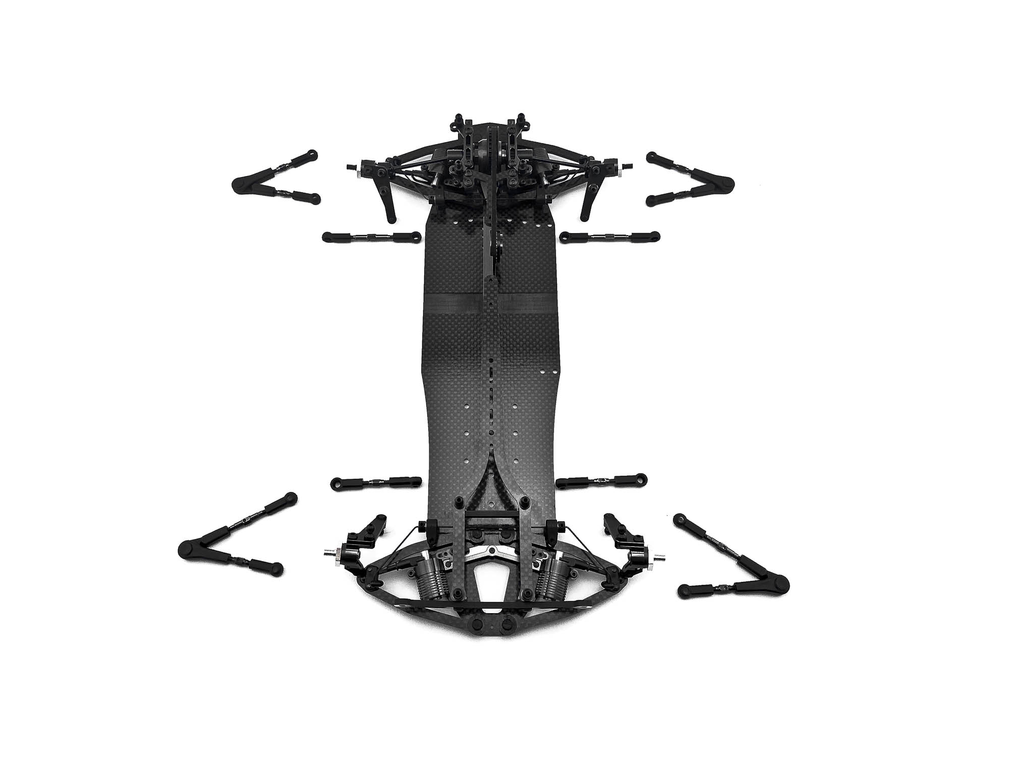
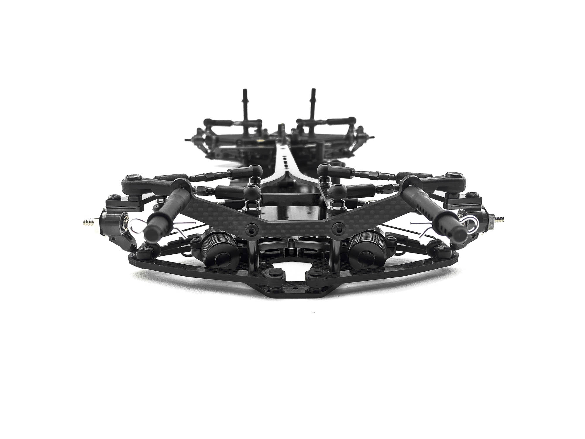
Front end links all installed.
Rear end also with all links. Interesting here -> how much the rear arms are shifted to the back compared to the previous chassis.
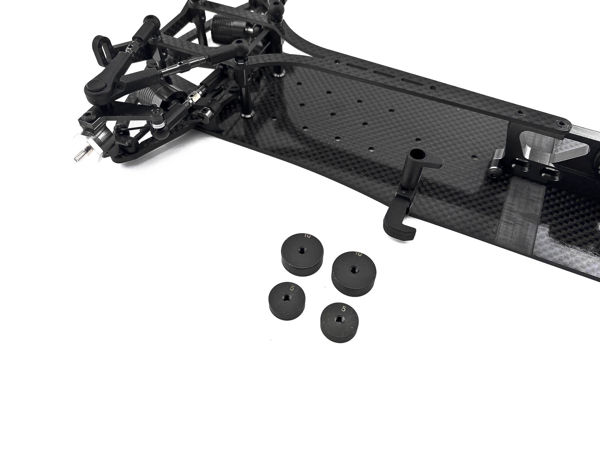
Ready for next STEP24 to install the battery holders and round weights.
Screw the SB3X10 screws with correct amount of shims into the motor mount to give enough clearance to the spur gear. Adjust the battery holders to suit well with your choice of shorty LIPO battery.
The additional 10g. and 5g. round weights can be used to fine tune the balance of the car. Note the chamfered side of the weights at installation.
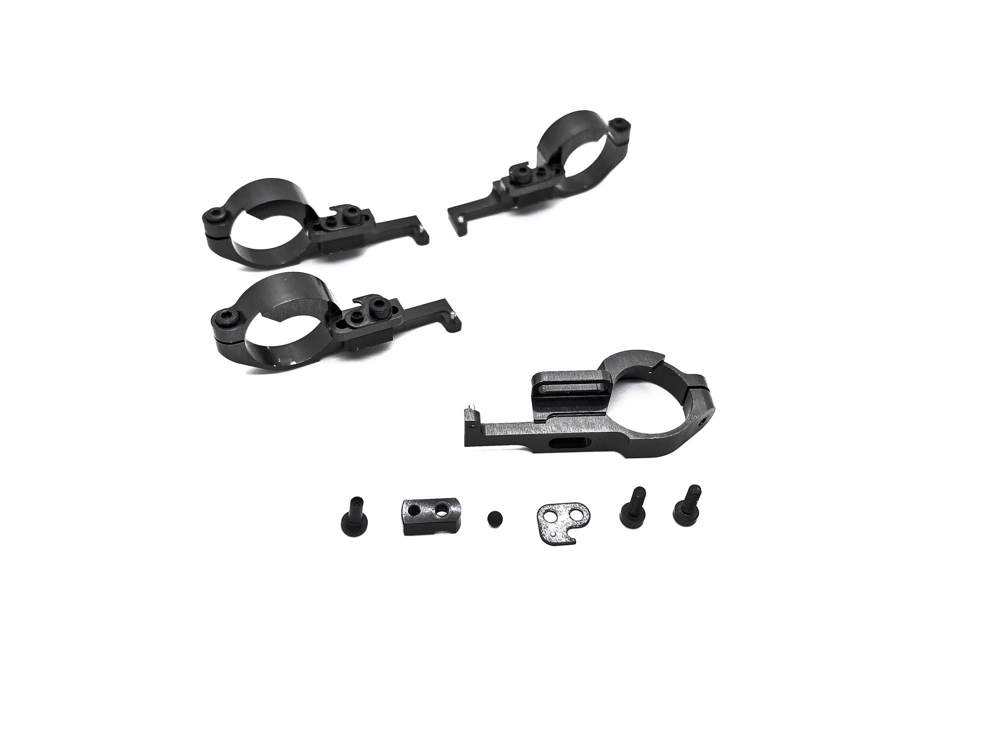
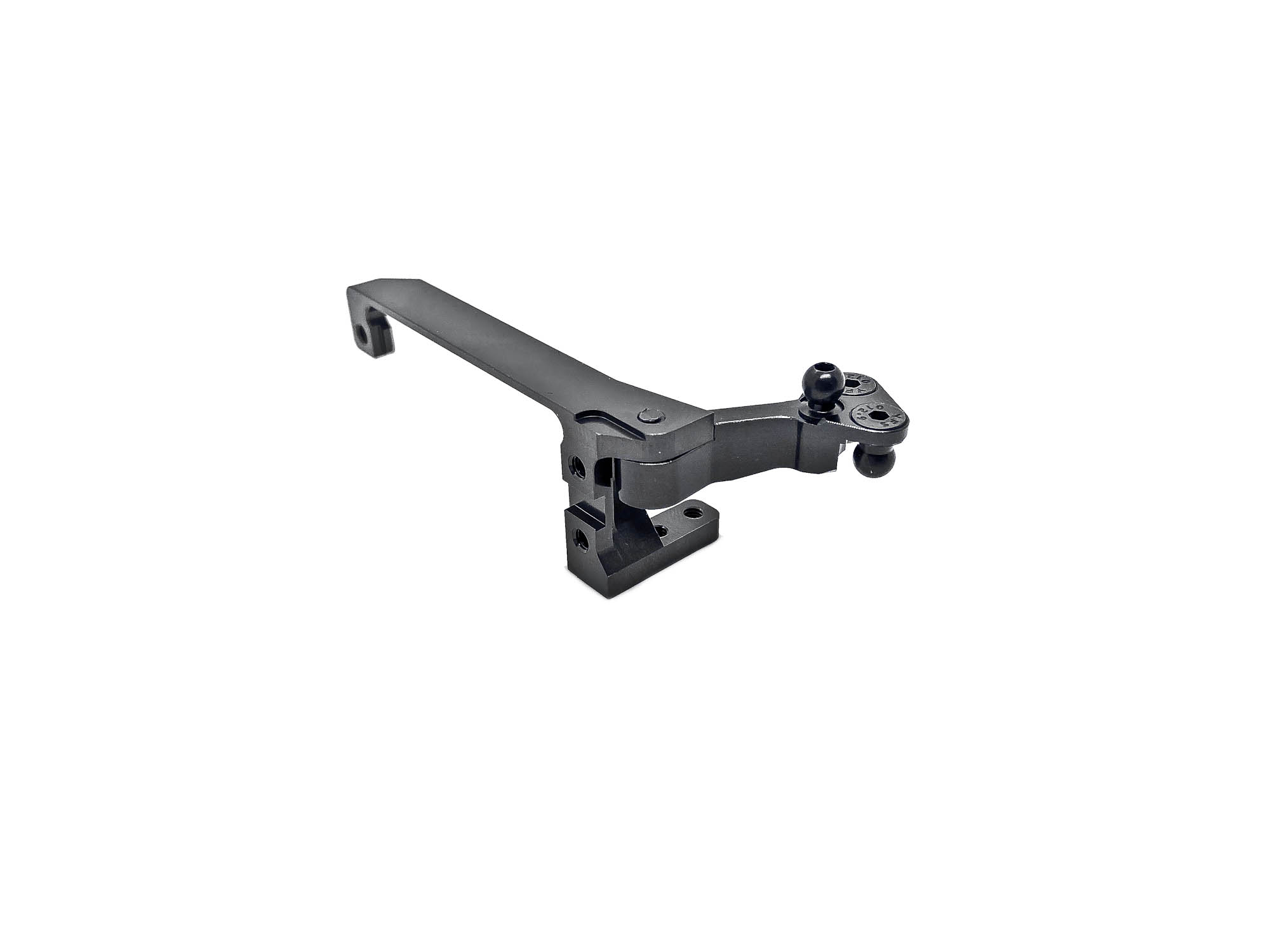
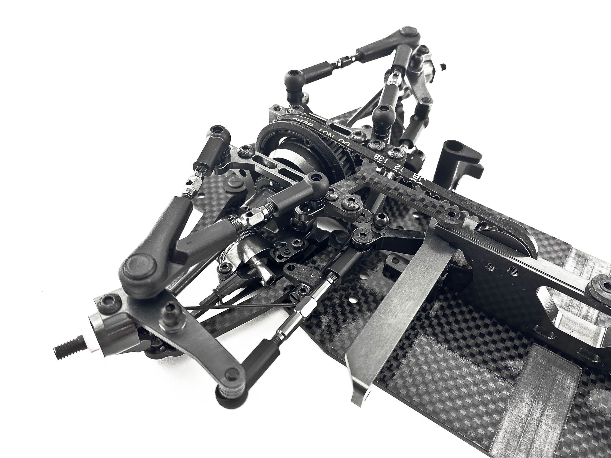
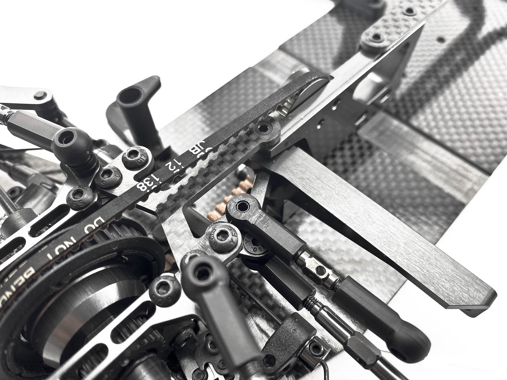
Another big part of the Evo is the totally new designed steering unit. It combines servo holder and steering holder in one part.
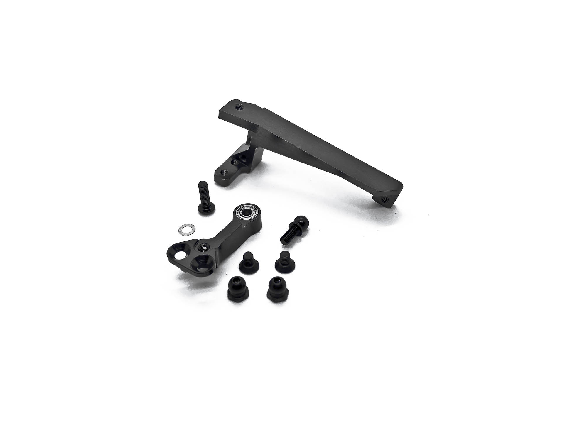
The single bell crank design is proven to work outstanding by the A800MMX TC car.
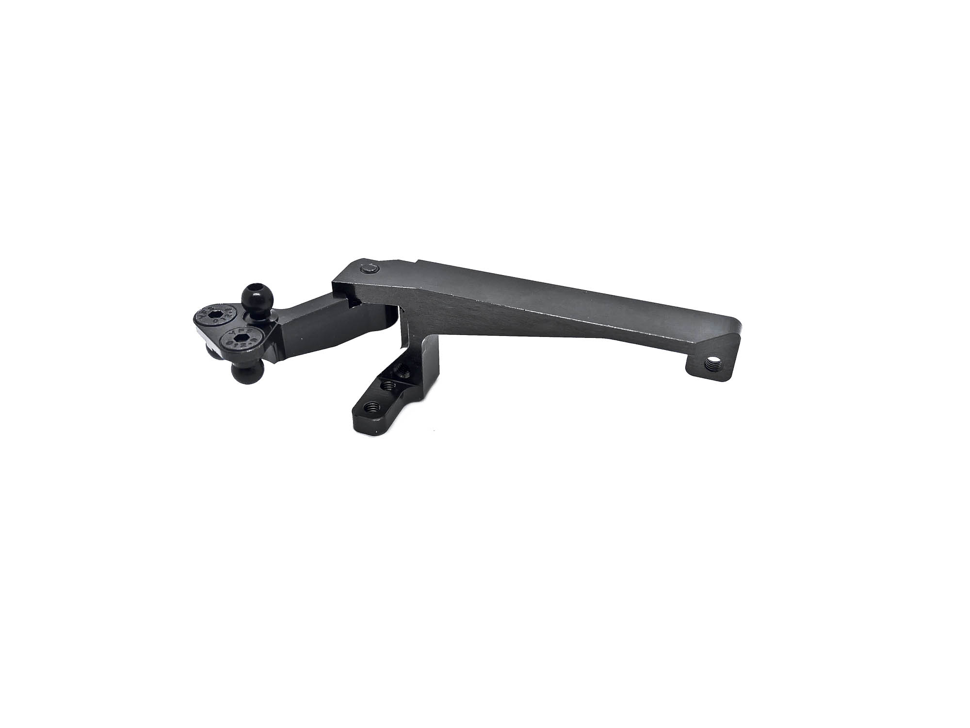
Build in steering limiter of the bell crank itself will ensure correct and similar endpoints.
Screw the steering/servo unit onto the chassis and snap in the steering links.
IMPORTANT: You need to cut off the top side of inner P13-4 ball cup to get clearance for the steering link. In my picture I didn't even cut enough and needed to remove a bit more later on.
EVEN MORE IMPORTANT: We recommend to use servo horns with maximum 17-17,5mm length!!
As you can see here, its all a very tight but perfect fit. The correct horn size is a must to ensure perfect handling.
The Ackermann setting is fixed and can't be changed, similar as the previous A800FX.
Make sure to use the cutted P13-4 on the inner side of the steering link. May even more cutting is needed as shown on my picture, depending on servo and horn.
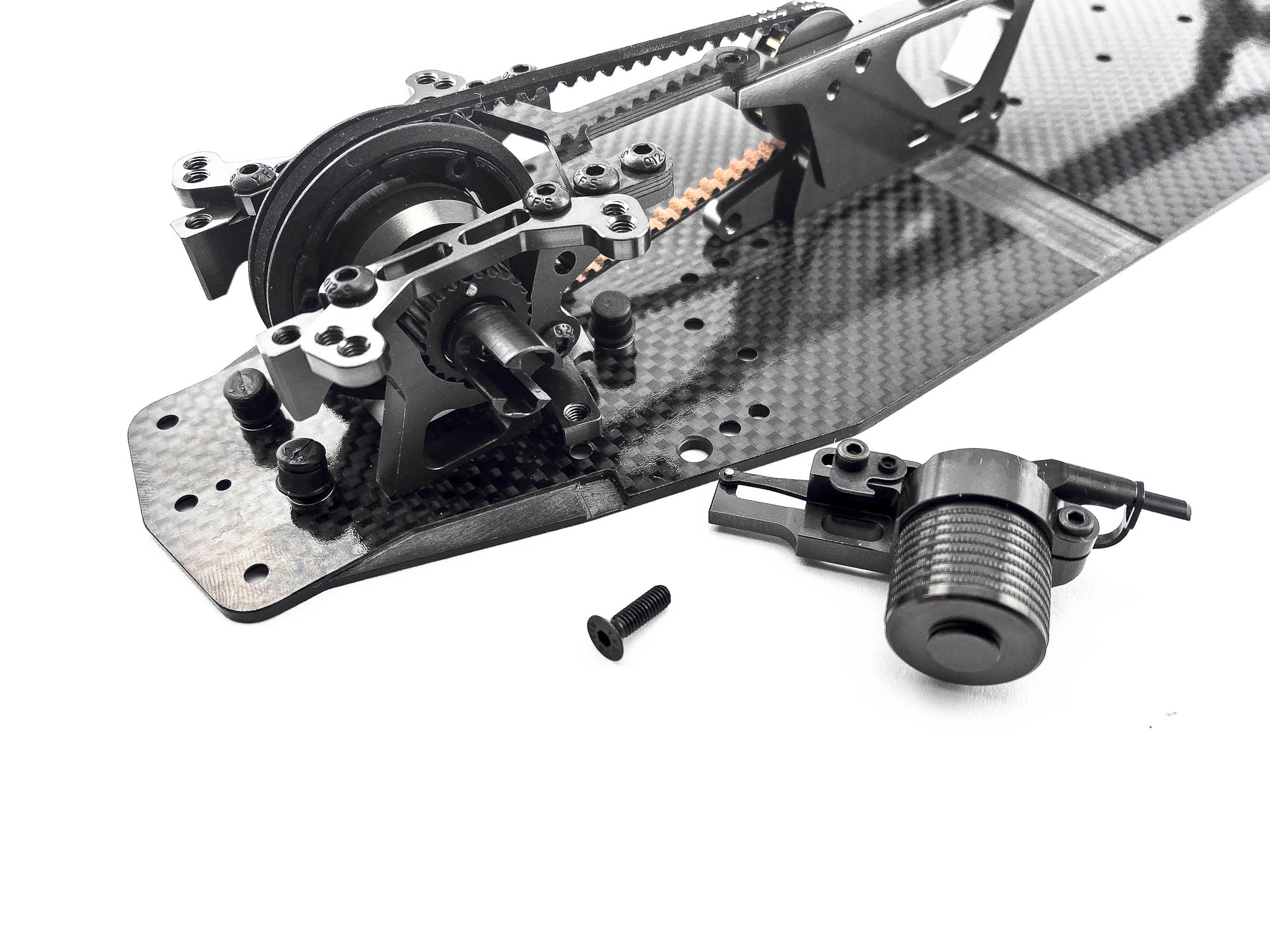
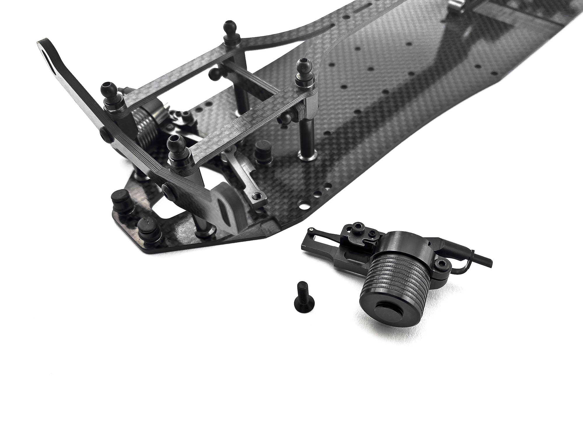
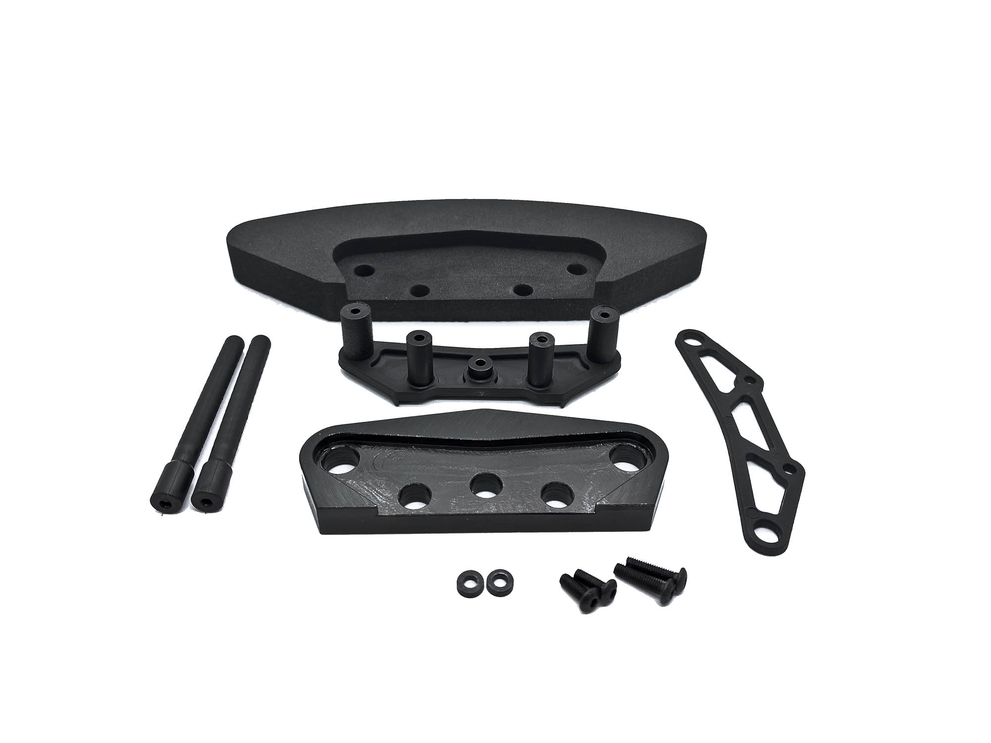
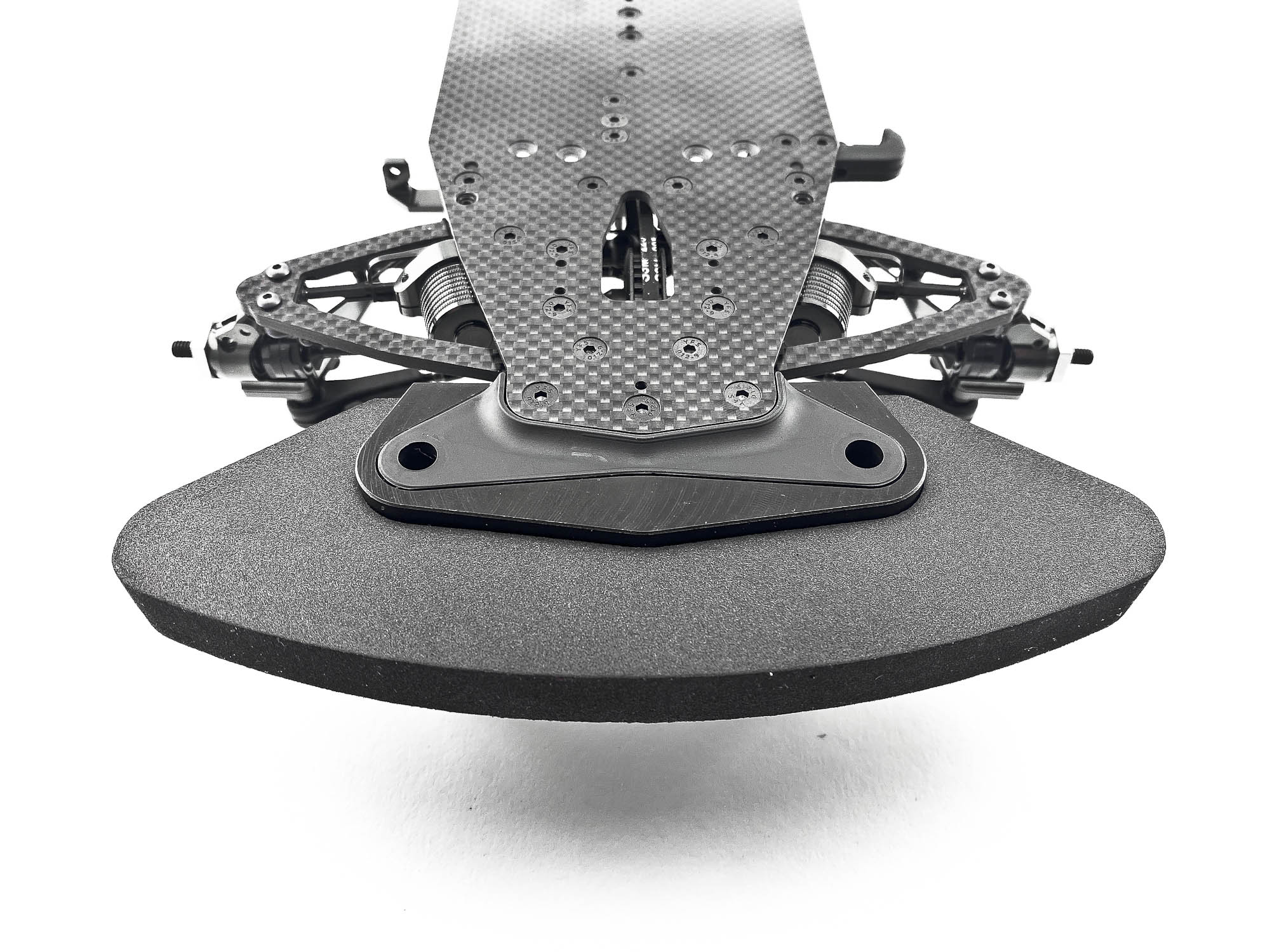
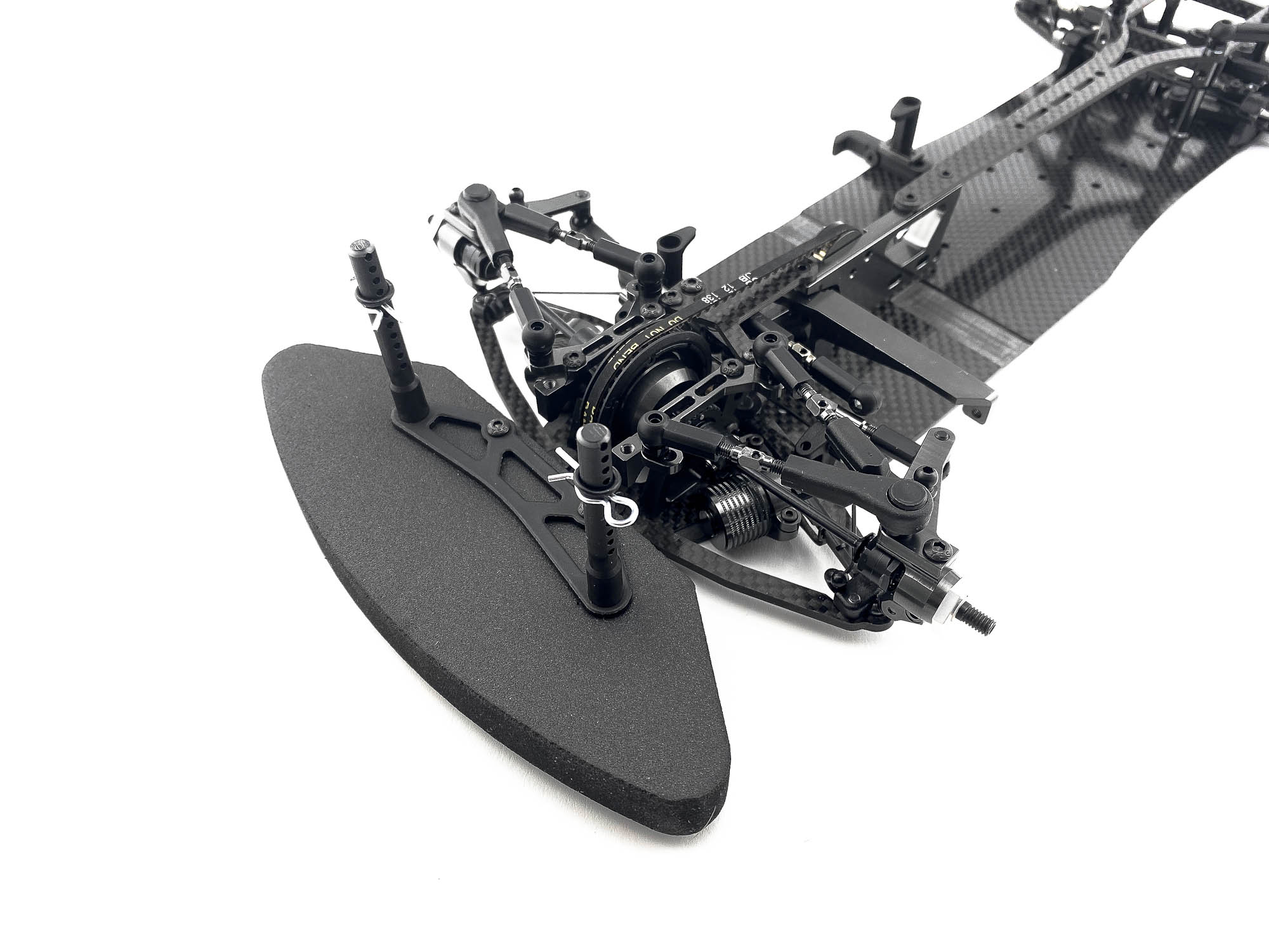
The front bumper also got an update with the new ST230 bumper weight.
All other parts of the bumper unit remain the same.
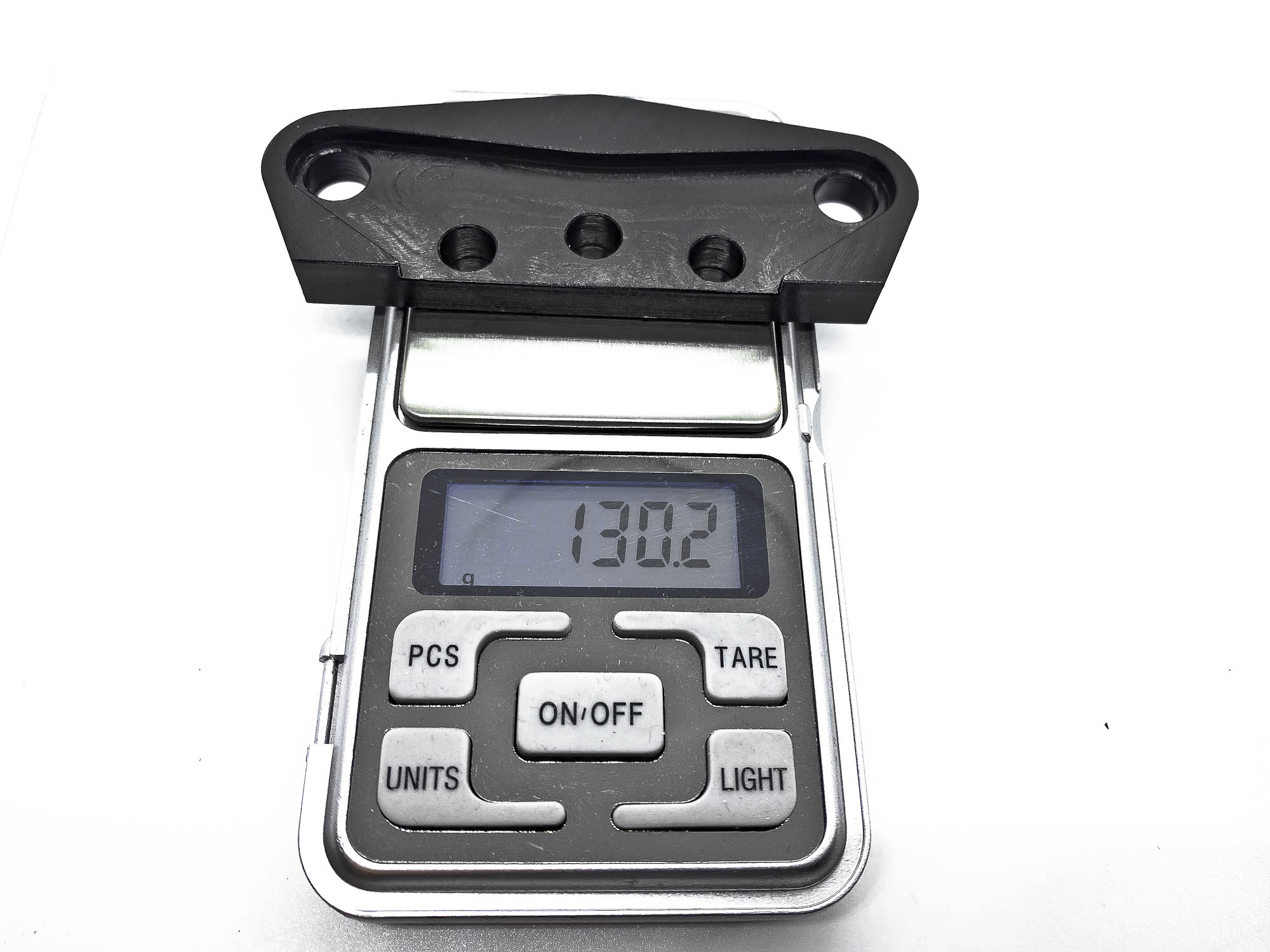
With 130g it's ~15g more heavy as the old ST265 with all round weights.
The ST230 doesn't allow to remove/add any round weights.
Lower side of the bumper. The ST230 fully surrounds the P14-1X.
Installation of the front body posts and upper bumper. May you have a look for the optional carbon bumper plate C07A.
Attach the rear body posts to the C105A. The adjustable holder is now also standard in the FX Evo.
The spur gear is hold in place by the AT55M spur nut. I am using AXON TCS 64DP spur gears, mostly in 100T or 102T size.
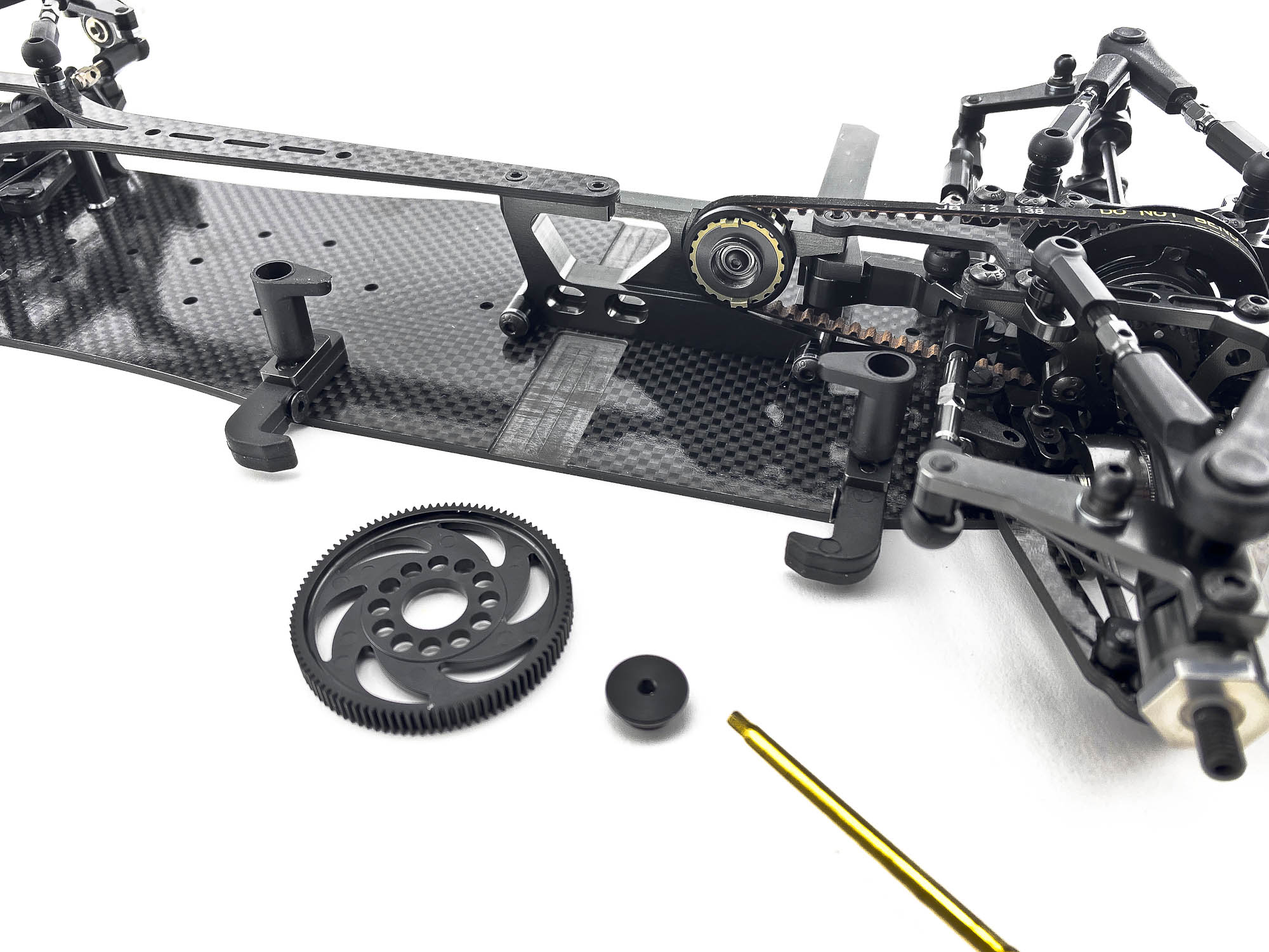
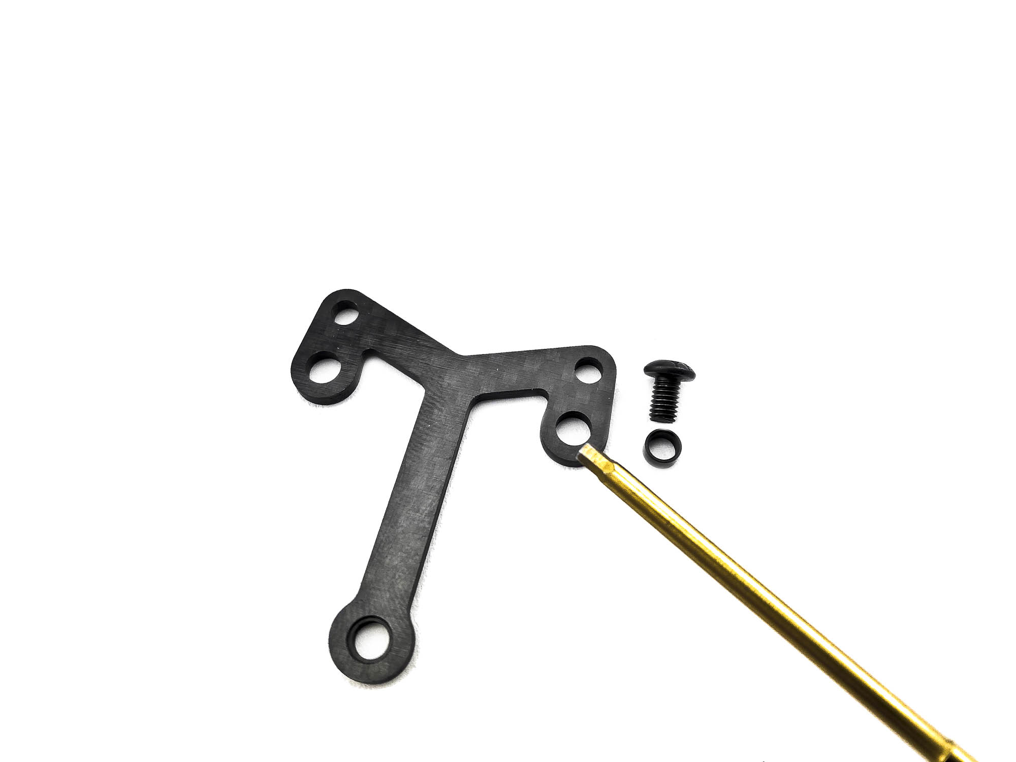
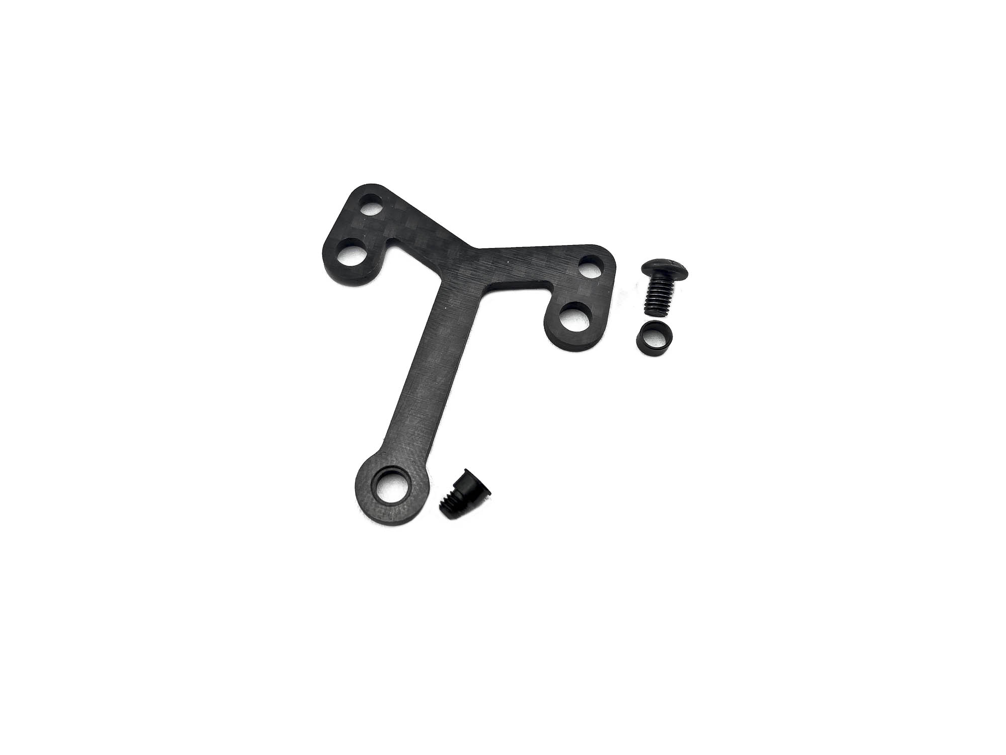
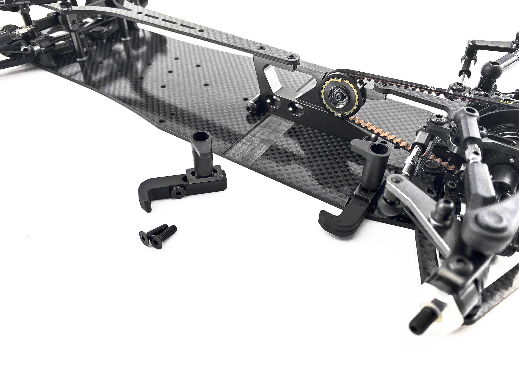
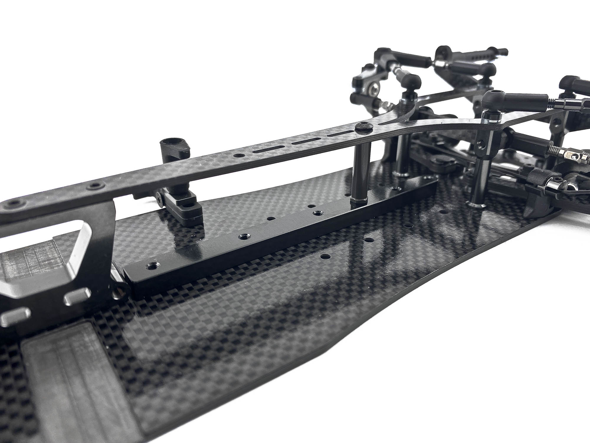
Another new feature of the FX Evo are the rear stiffener and rear strut.
It allows a lot more flex options as previously. Make sure to use the 0,5mm shims under the AM30FX brace!
You can install up to two AT159 struts.
One is included in the kit. This struts increase the stiffness a lot when connected to the C27FX-2 topdeck.
Wheelnuts and DG1X damper gauge are the last parts to finish the build.
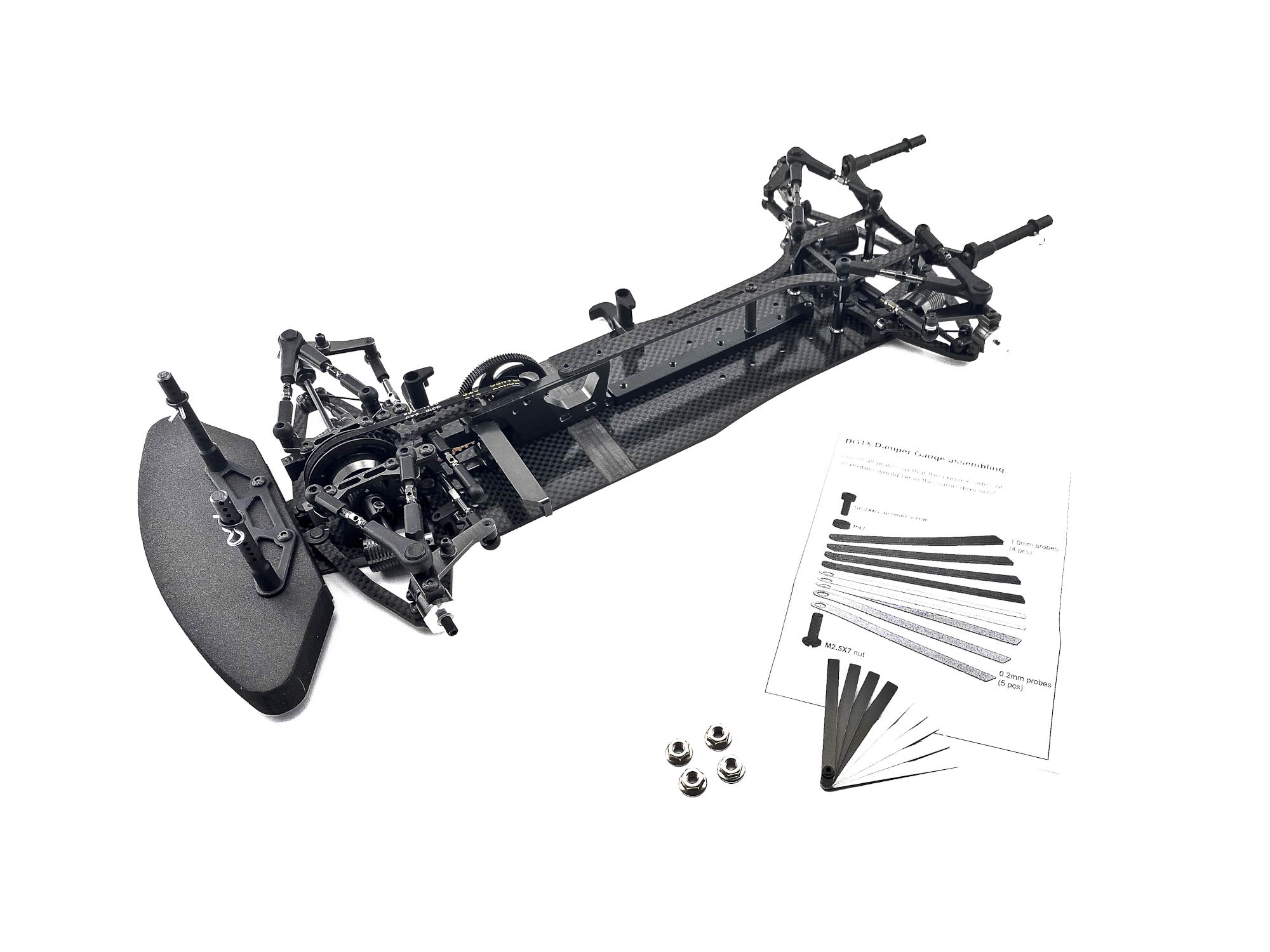
Hope you enjoyed the build! Wish you a lot of fun at the track.
|
