|
- A12 Build - Tips and Tricks by Max Machler -
During the build up of my A12 I took some photos to share with you. Every picture of the album has some comments with some infos and tips. If you have any questions, please feel free to ask anytime. Like always its possible that I may didn't follow the manual steps by 100% :-) Use the manual as main - and see my build tips as addition to it.
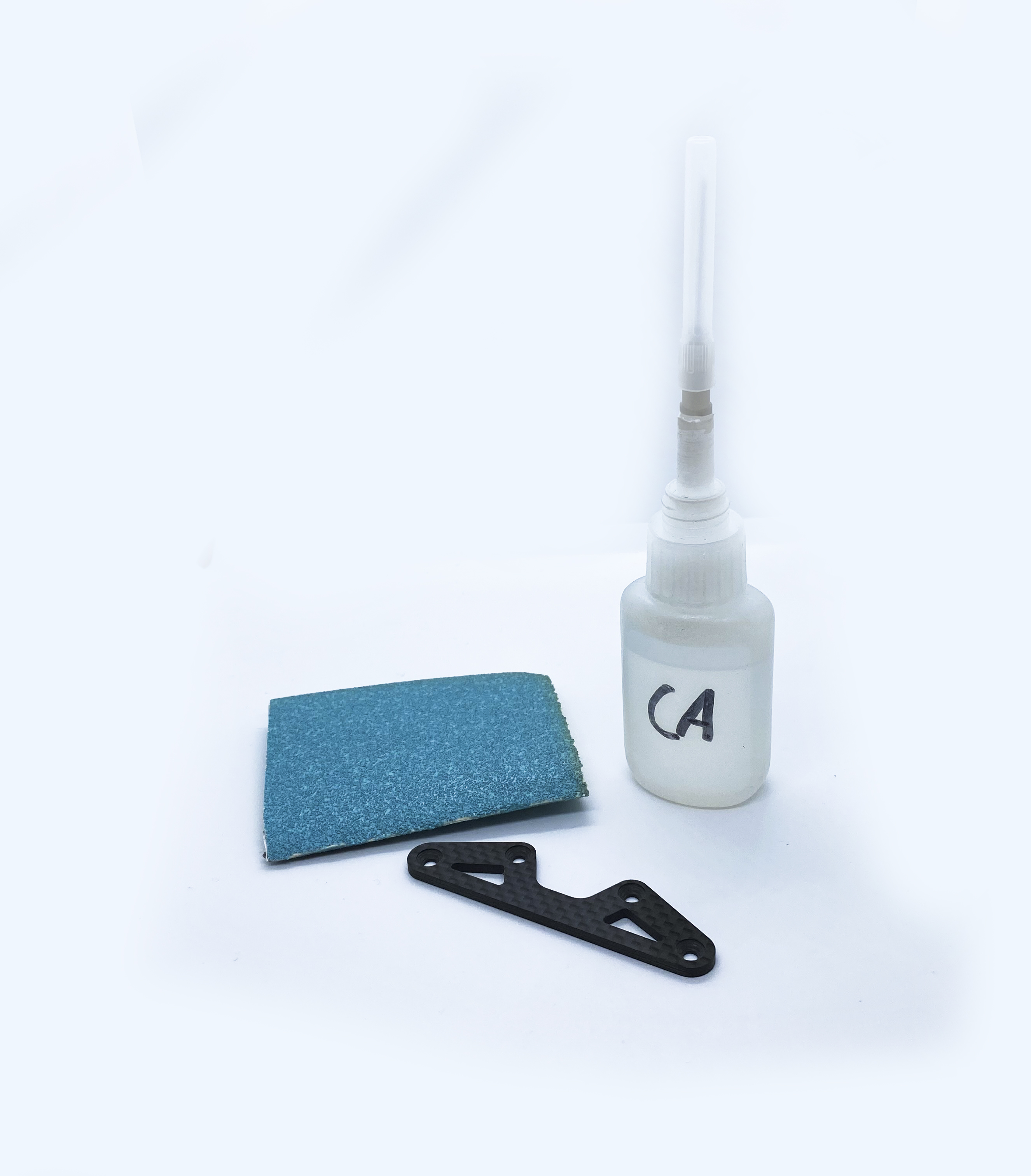
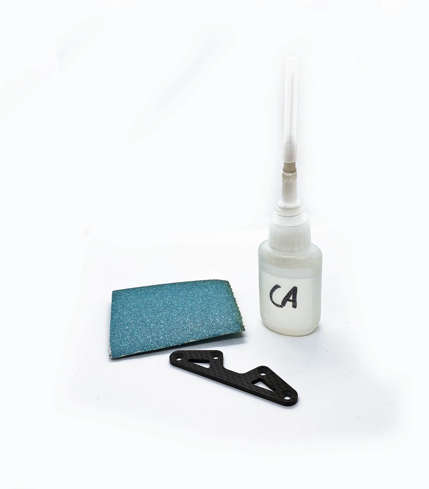
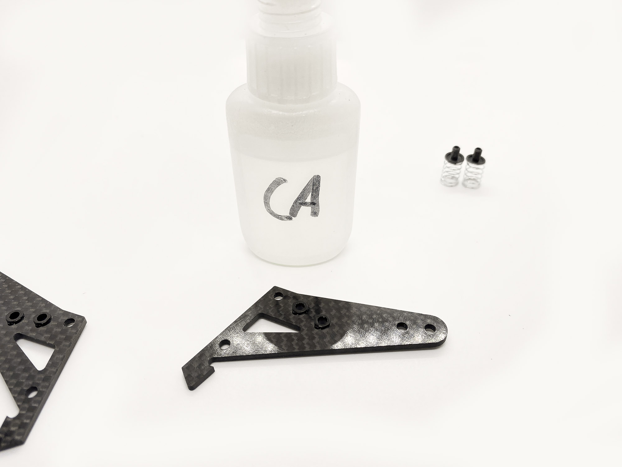
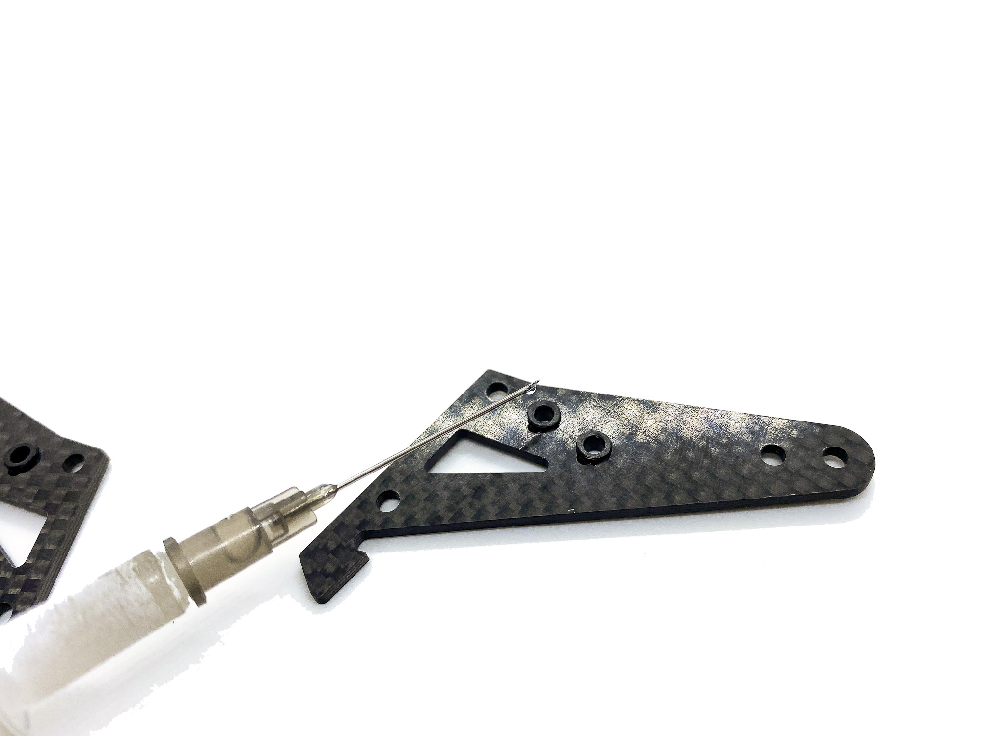
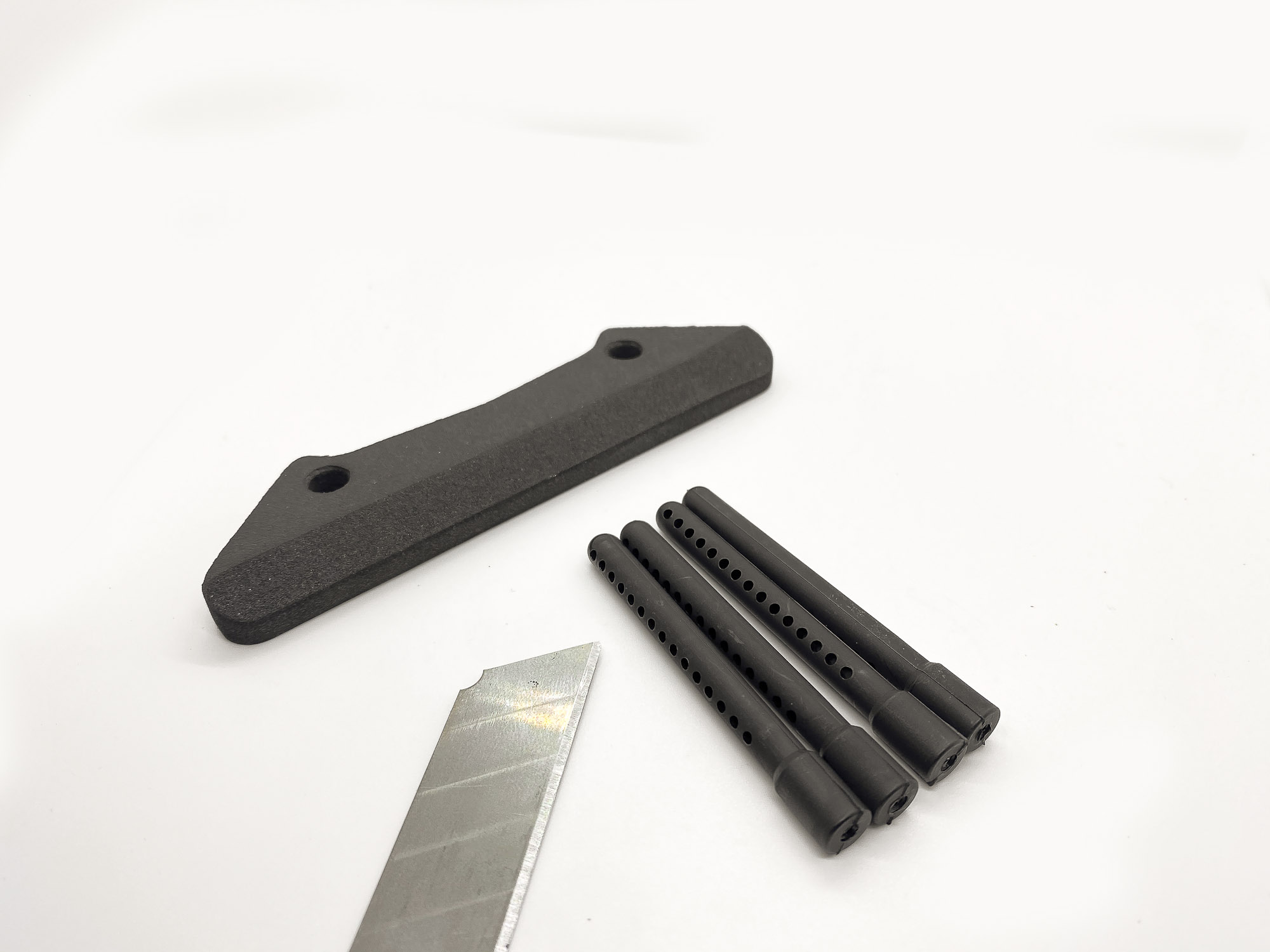
1: I recommend to seal the edges of the carbon bumper plate with CA glue. This extend the life of the plate a bit at crashes and also at riding of curbs.
I use 120 grid sandpaper to round the edges a bit before i put some medium thick CA glue on the edges as sealing.
2: First step is easy. Just follow the instructions and make sure to use the right shims (SH1.5W).
3: At the second step please makre sure to use the SB3X5AL Alloy screws!

4: The Alloy screws will center the front suspension plate additionally beside the existing recess in the Battery plate. This ensure that there will be no chance for any movement of this parts at crashes. And yes - this screws are strong enough.
Do NOT use any other brand steel/ti/alloy screws here!
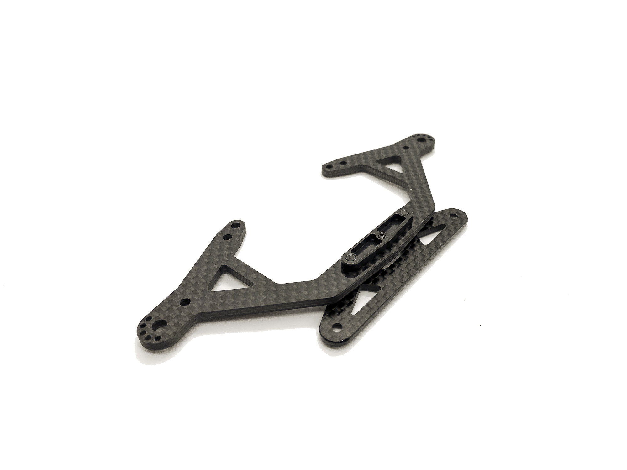
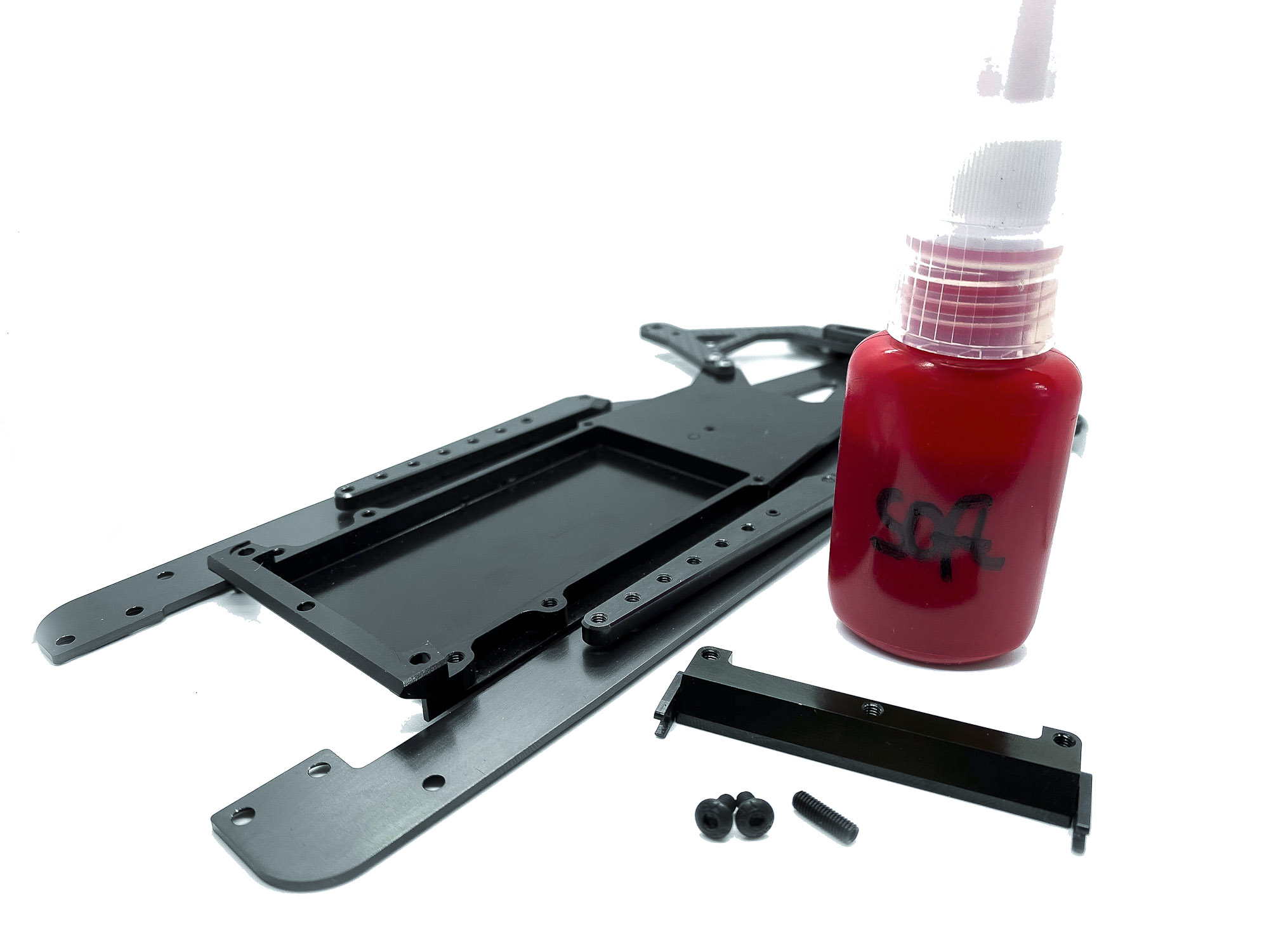
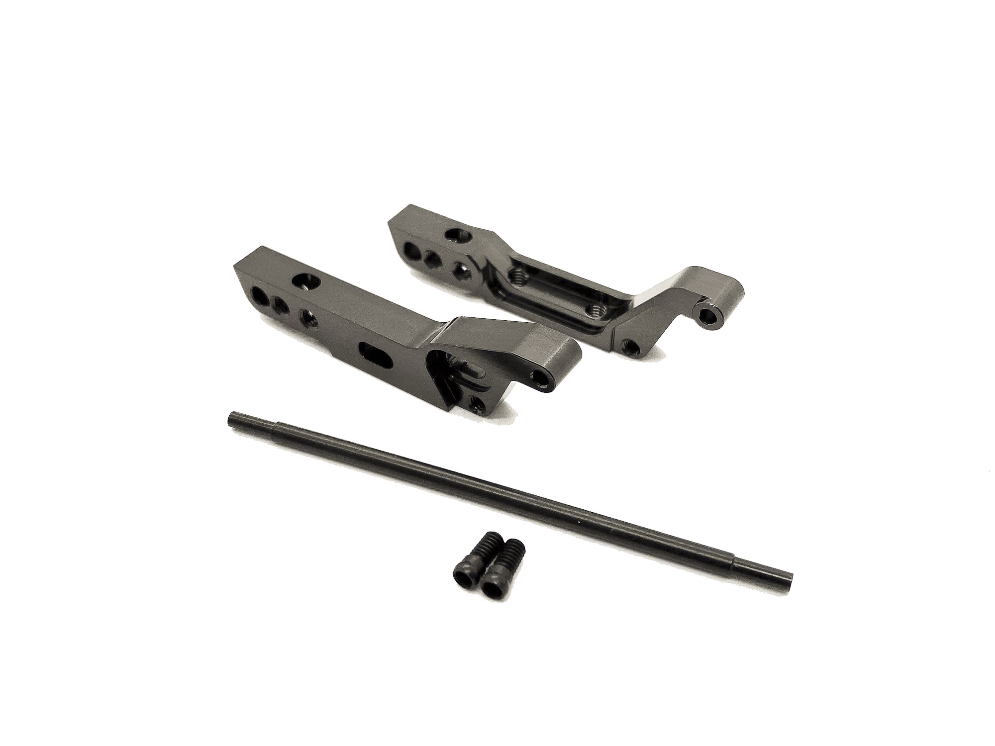
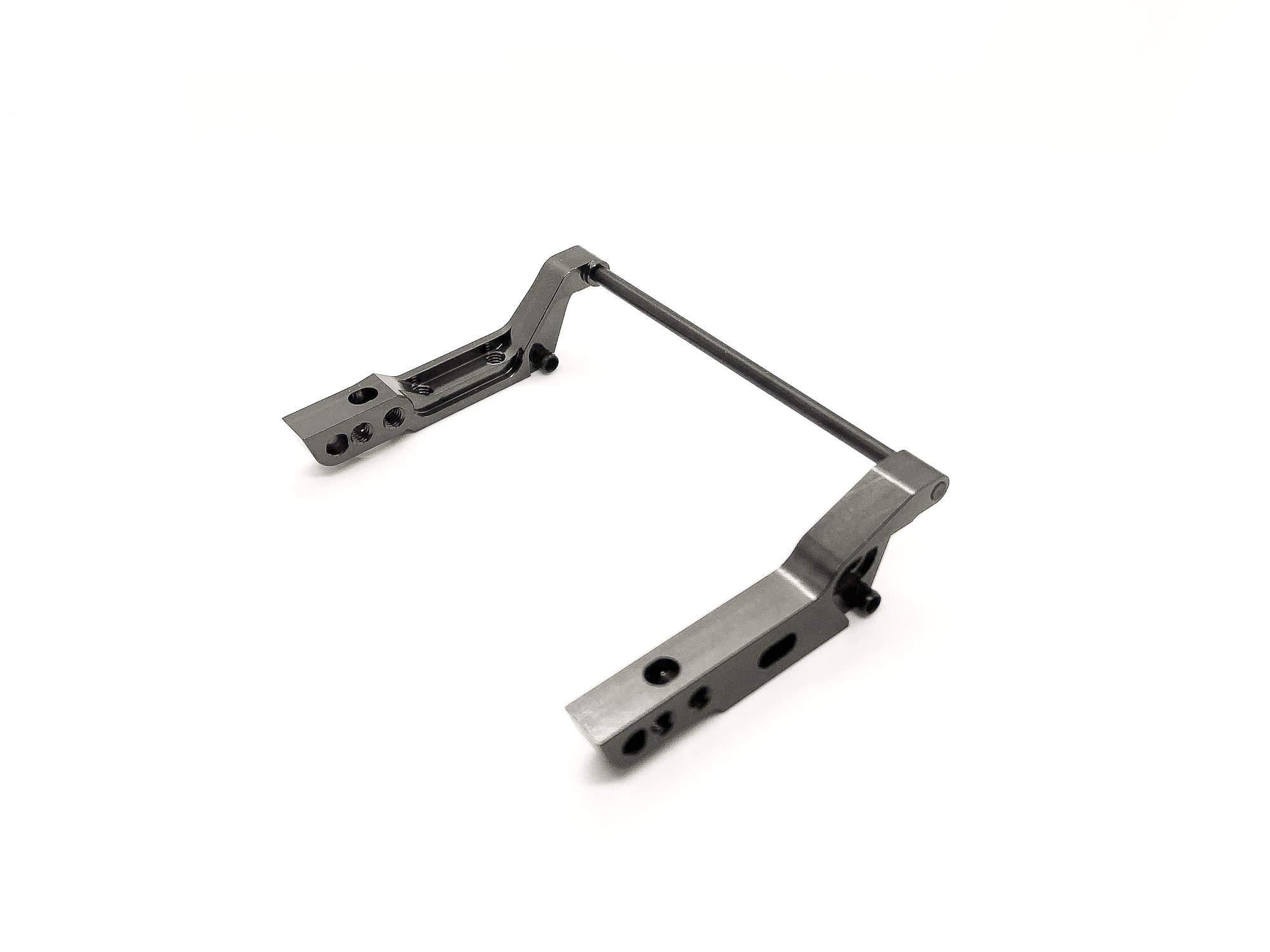
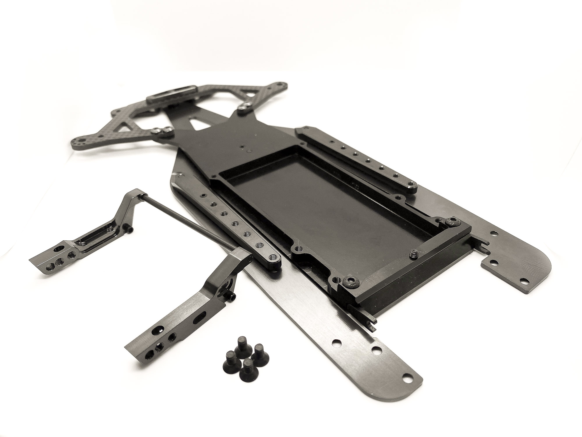
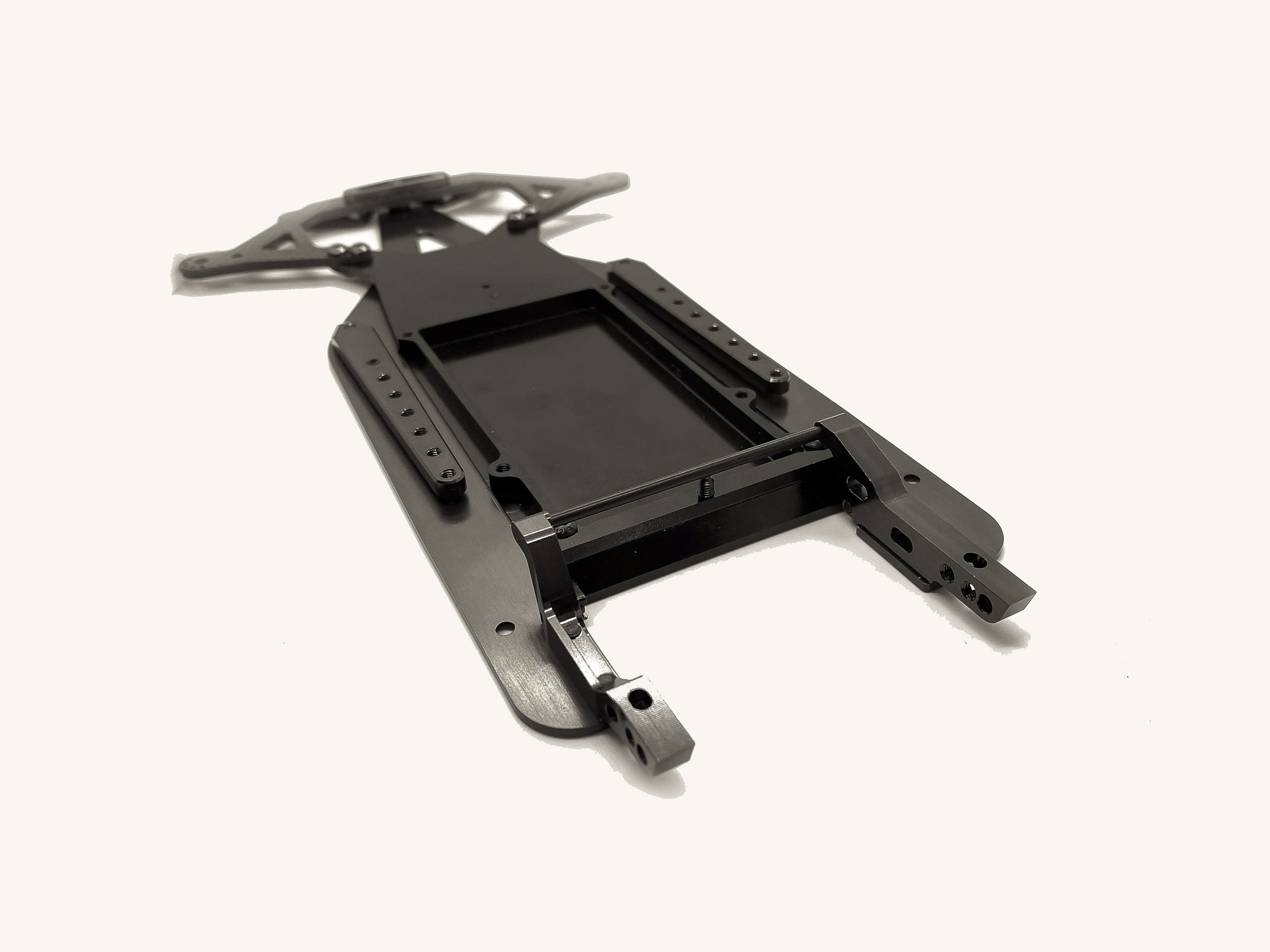
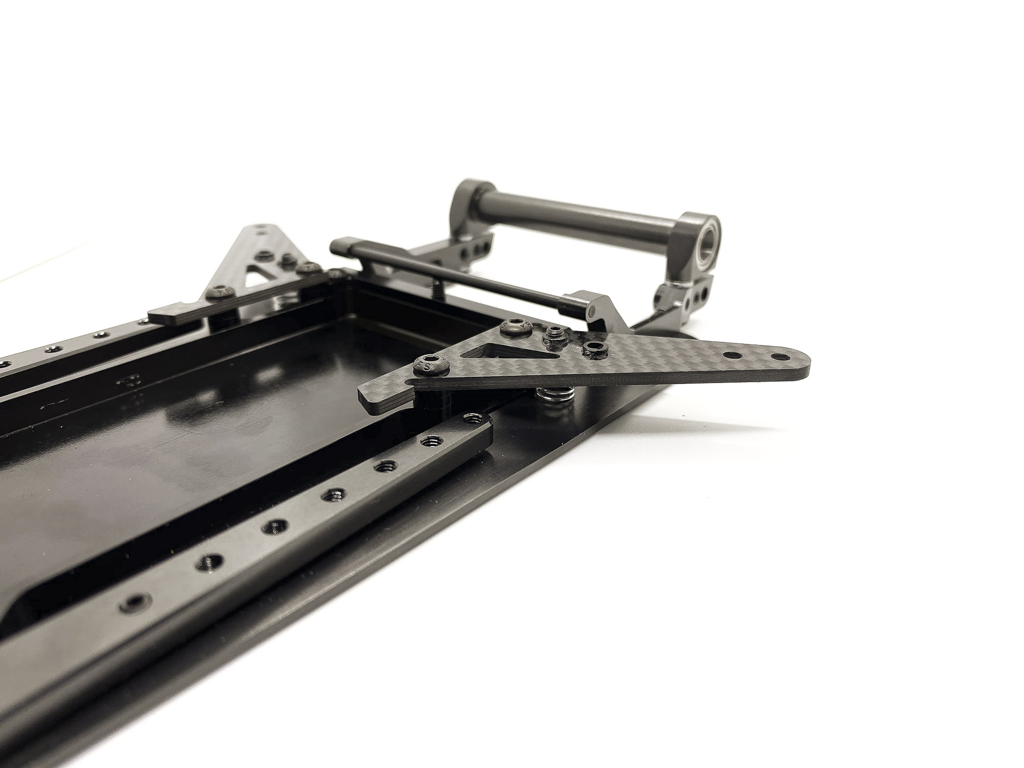
5: Next up we install the side braces at the chassis plate.
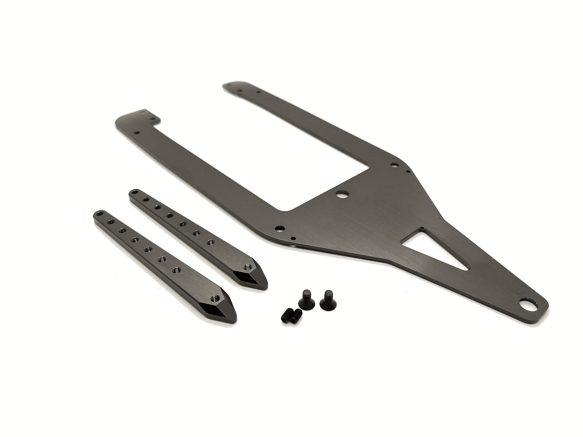
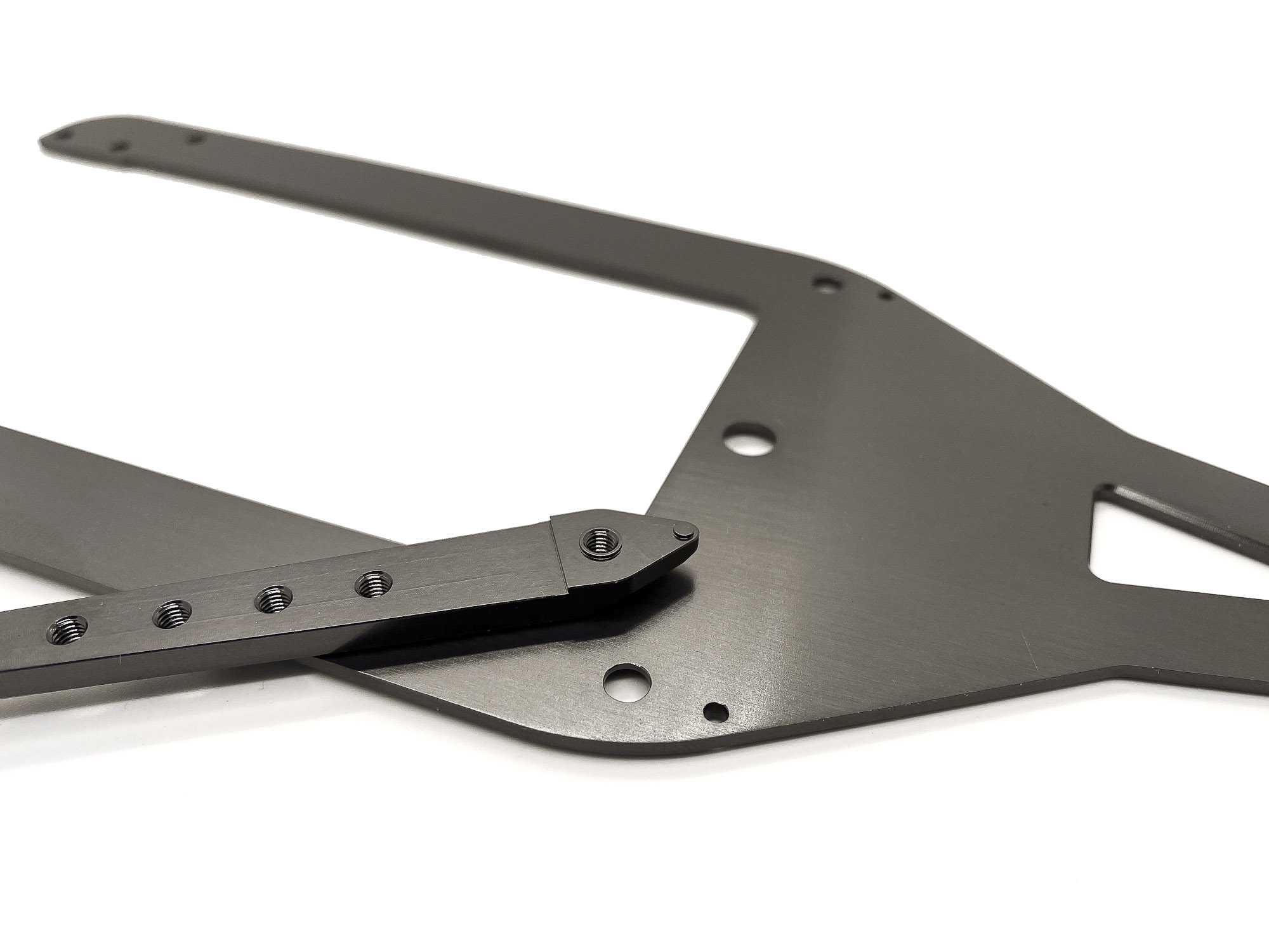
6: Make sure to place the braces correctly. There are a special nose and additionally centering via the screw and countersunk area of the part/chassis.
This ensure there will be no moving of the brace in case someone crash into your car from the side.
7: The SS3X5 screws in the side braces are "setting options". Important - use a small drop of soft thread lock to secure the screw.
Most front hole = softest setting
Most reward hole = hardest setting
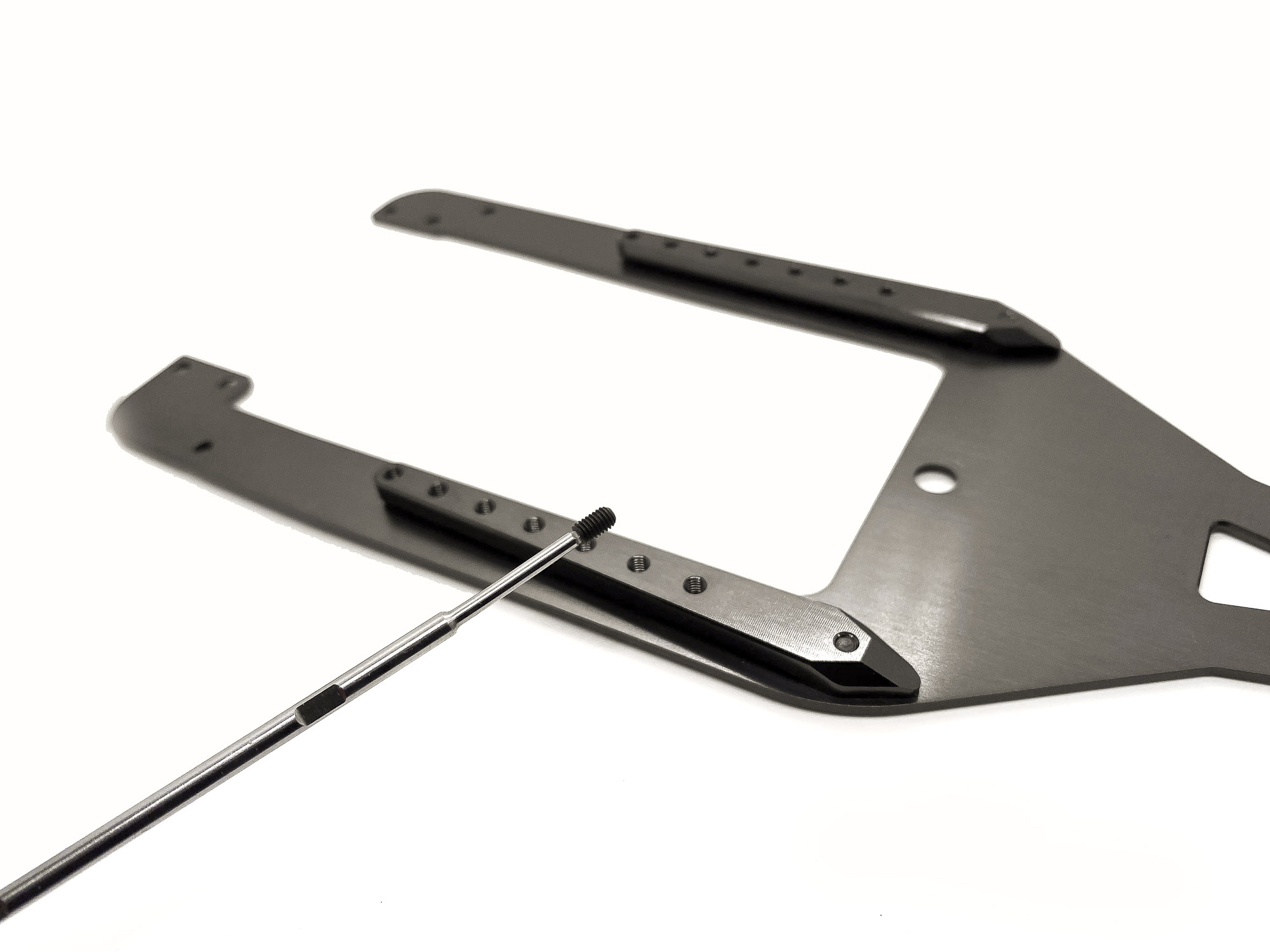
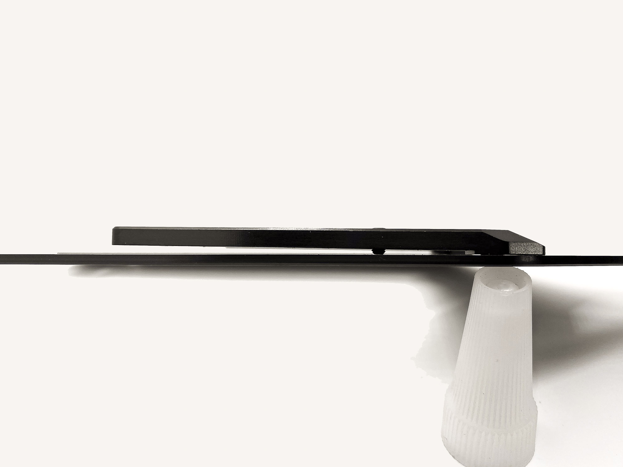
8: As initial I used the most soft setting.
I screwed it till it slightly touches the chassis.
Make sure to set the same "pre-load" on both side braces.
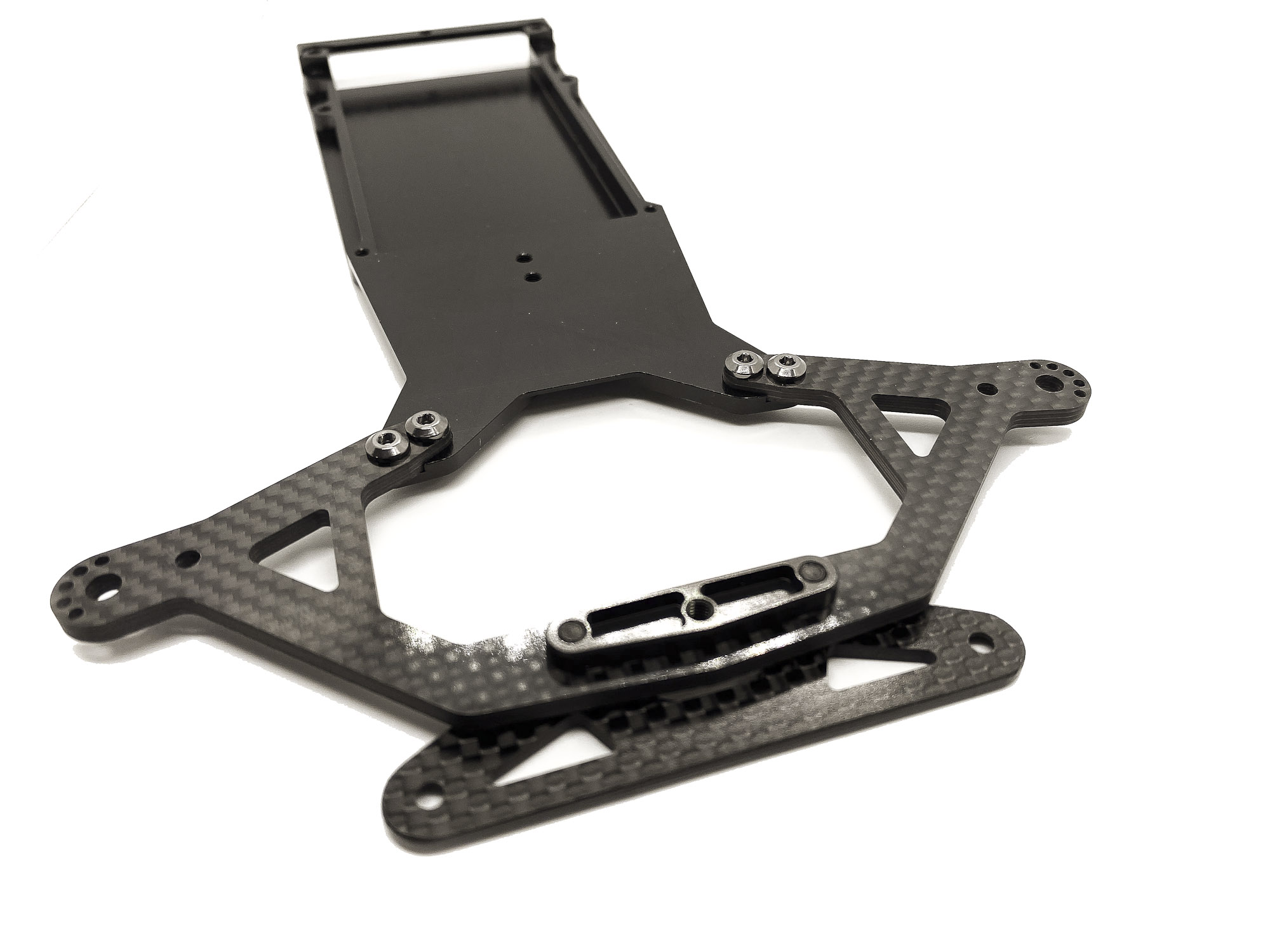
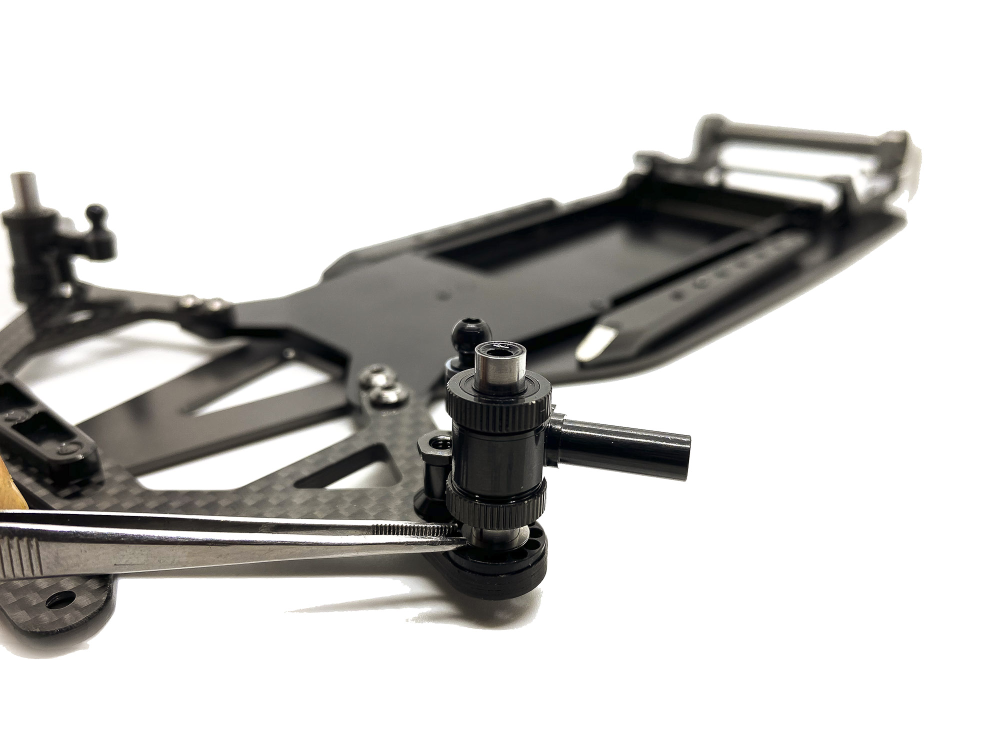
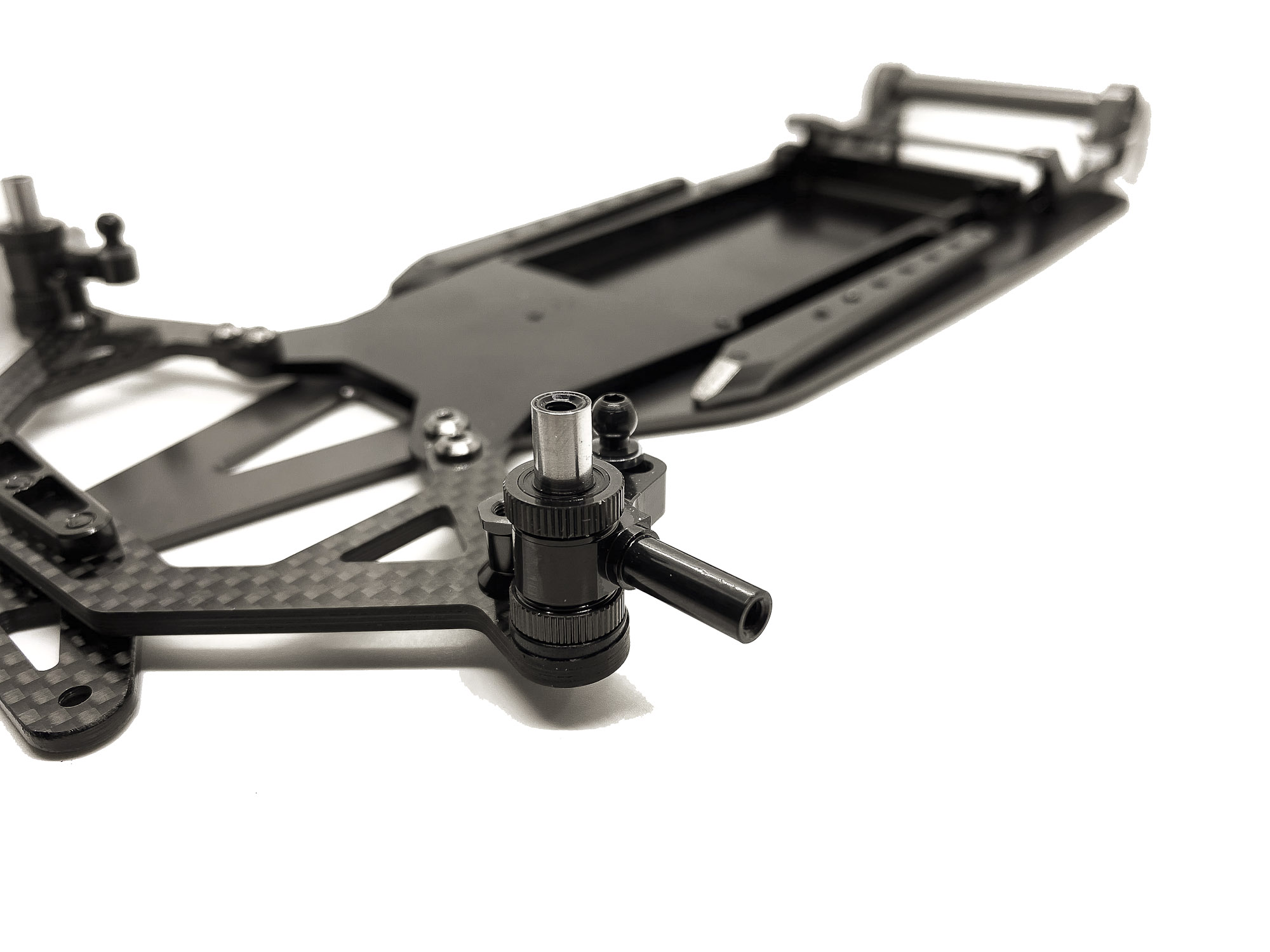
9: MARRIAGE time!
This is one of the main features of the A12. The longitudinal connection of Battery Plate and Chassis via special made joints.
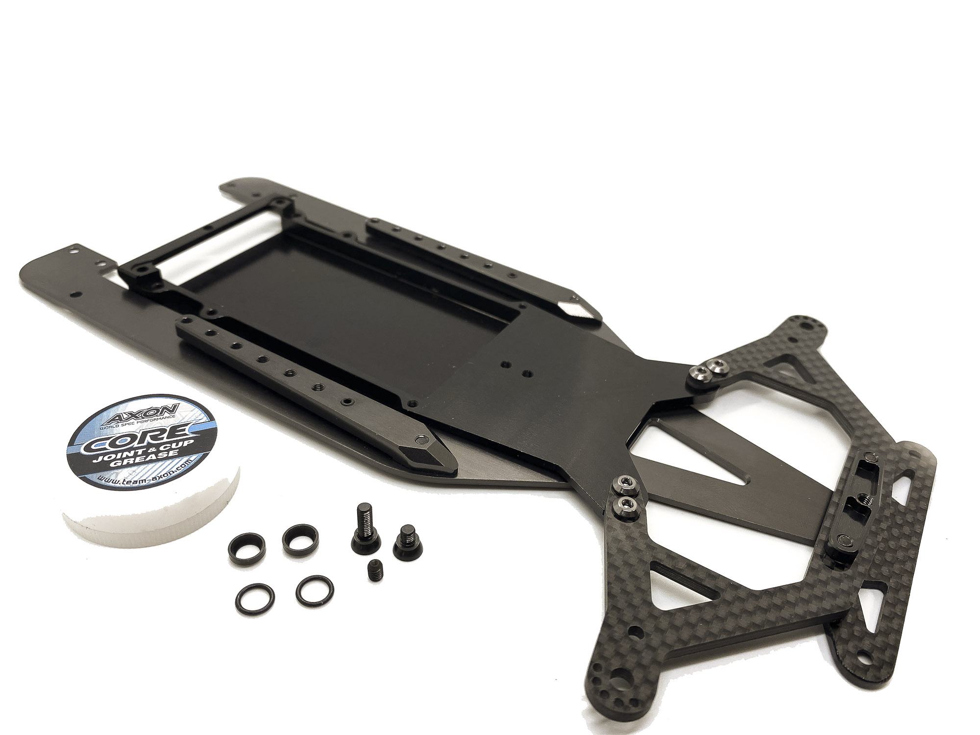
10: I like to use some Joint grease as lube in the cups.
At this case AXON "Joint & Cup" grease.
Small amount is enough.
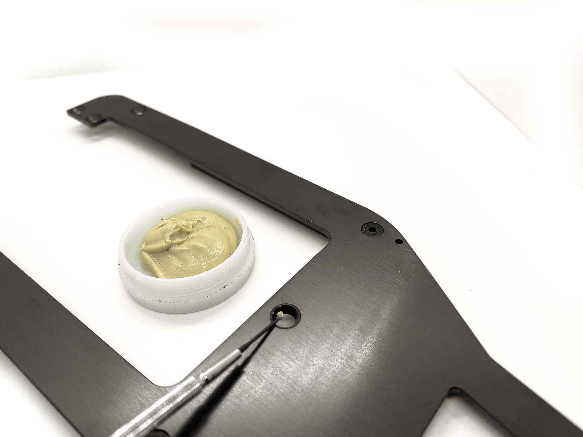
Build tip
Don't forget to use some grease for the assembly of the two main chassis joints when building or service your A12!
Both, the ball cup (ST1205) and the ball stud (ST1209M/L) are made from steel. Without any lubricants you will face excessive wear and less smooth operating which results in worse performance.
Take care at this step!
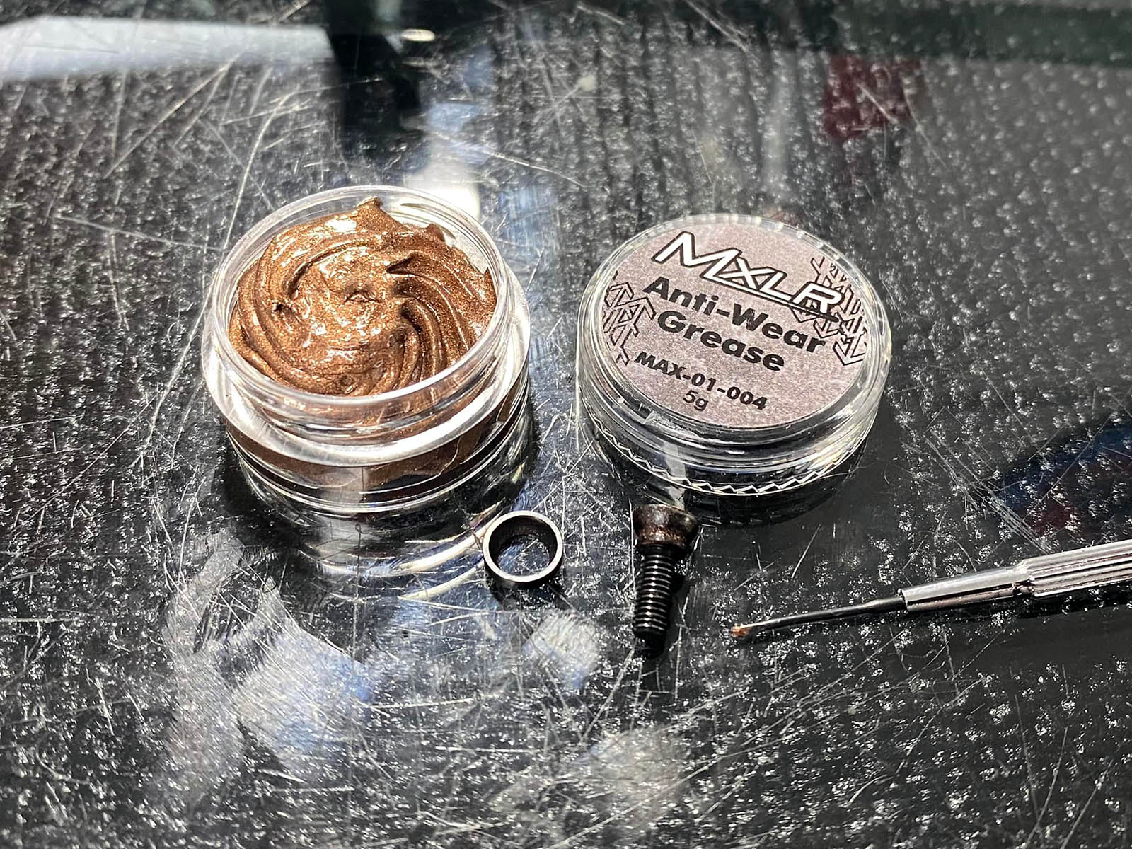
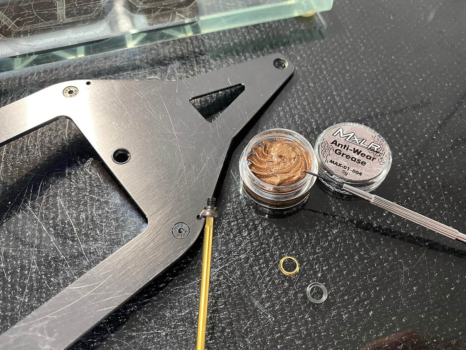
I use the MXLR Anti-Wear Grease which is the best option for this area/needs! It builds a super thin layer which protect against wear, and assure a smooth operation at any time!
It's important to NOT add too much grease in the coupling! I use a small screw driver to add two small "tips" to the ball joint, then install it into the ball cup and rotate it to spread it well.
Like always - this may not improve the single laptime. But it plays a role in the big picture to get the maximum out of your vehicle! ✔️
|
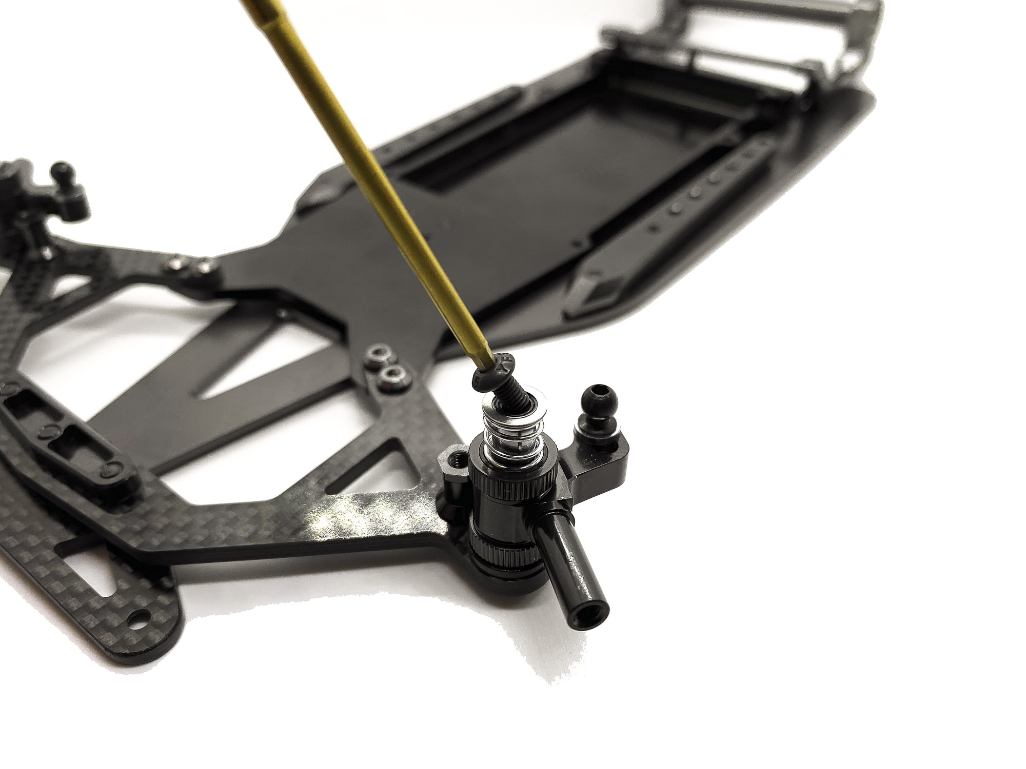
11: Don't forget the OR125 o-rings on top side before you screw the battery plate. Additionally - in front you need to place the third SH1.5W shim (on top of the o-ring).

12: Make sure both ST1209M and ST1209L screws are tightened WELL ! It's steel - so don't worry and tight them like men
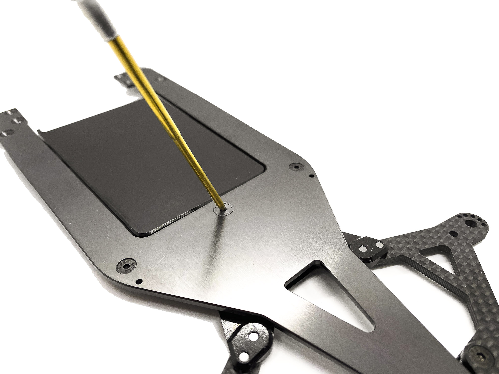
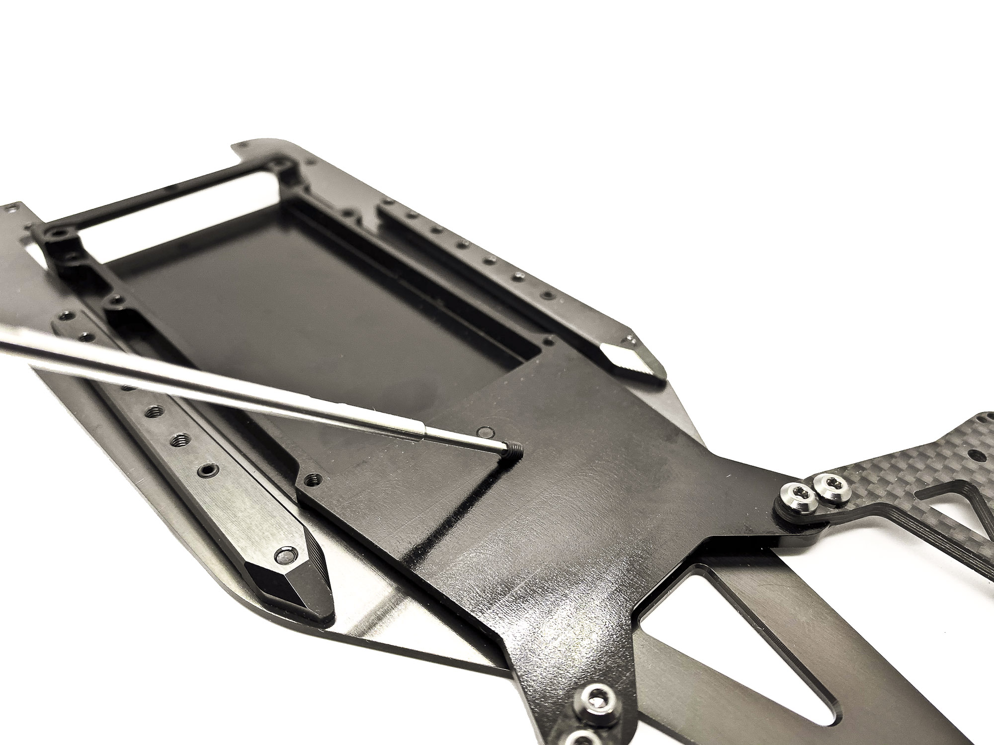
13: Very important - which shouldn't be forgotten - is the SS3X4 grubscrew from topside of the Battery plate. Make sure to use some soft threadlocker here as well!
The tip of the SS3X4 should just slightly touch the Chassis surface. No any force should be used here.
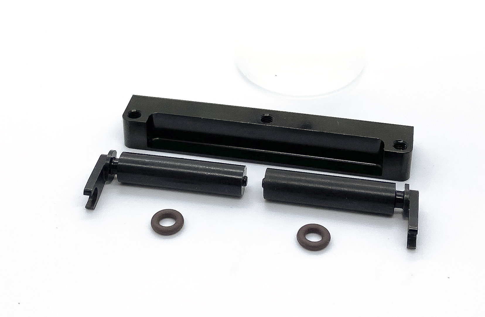
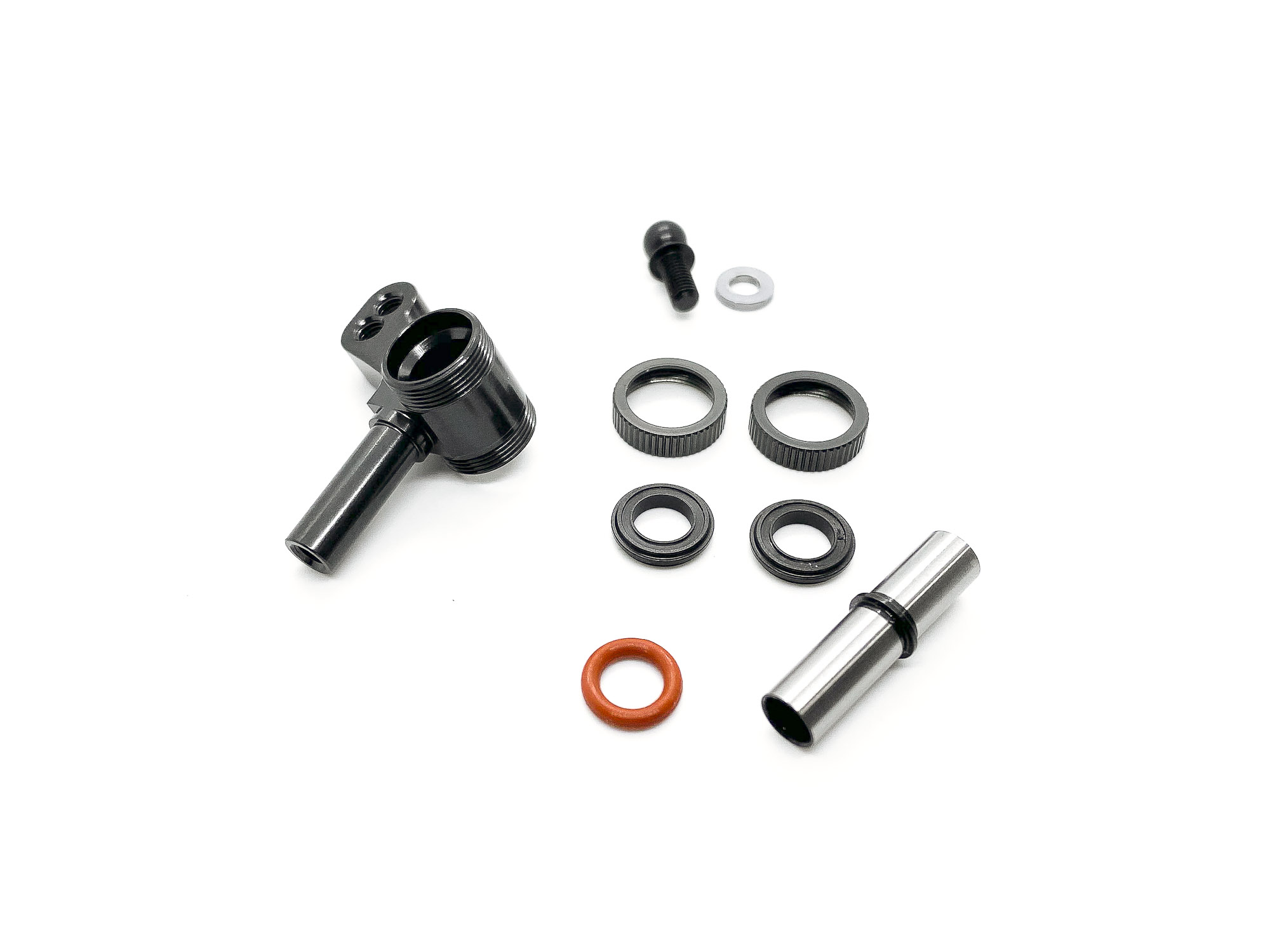
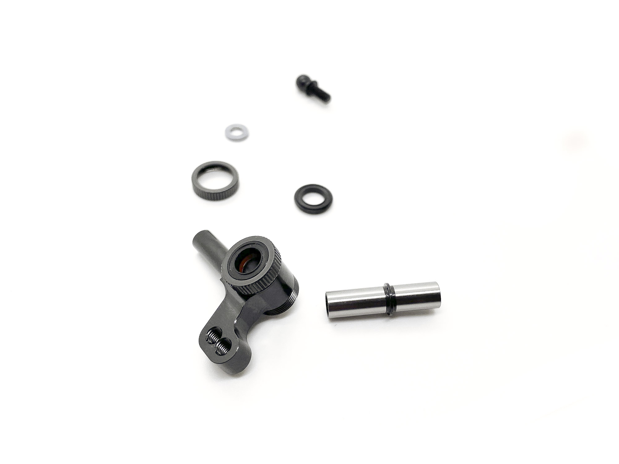
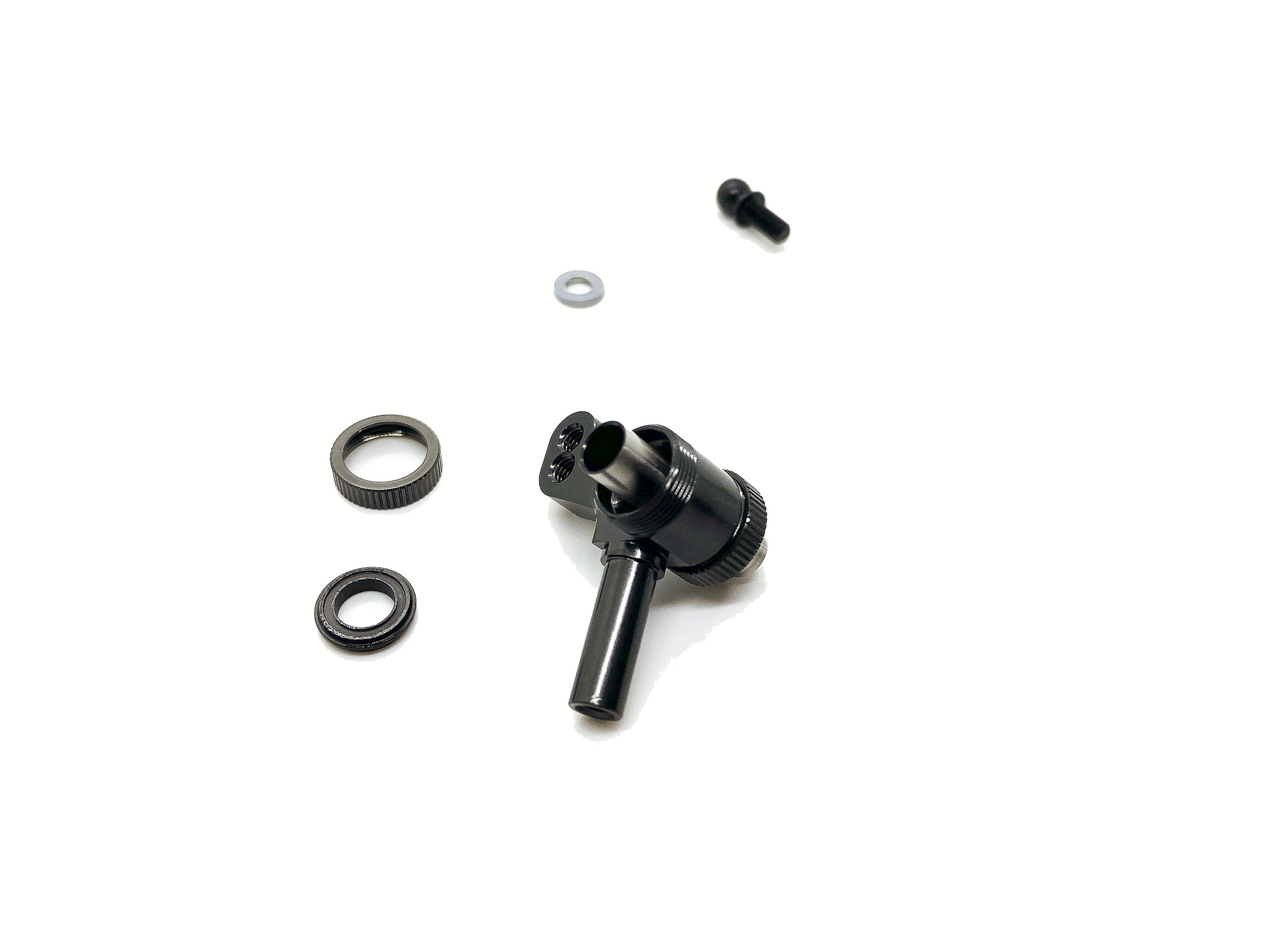
14: THE DAMPER!
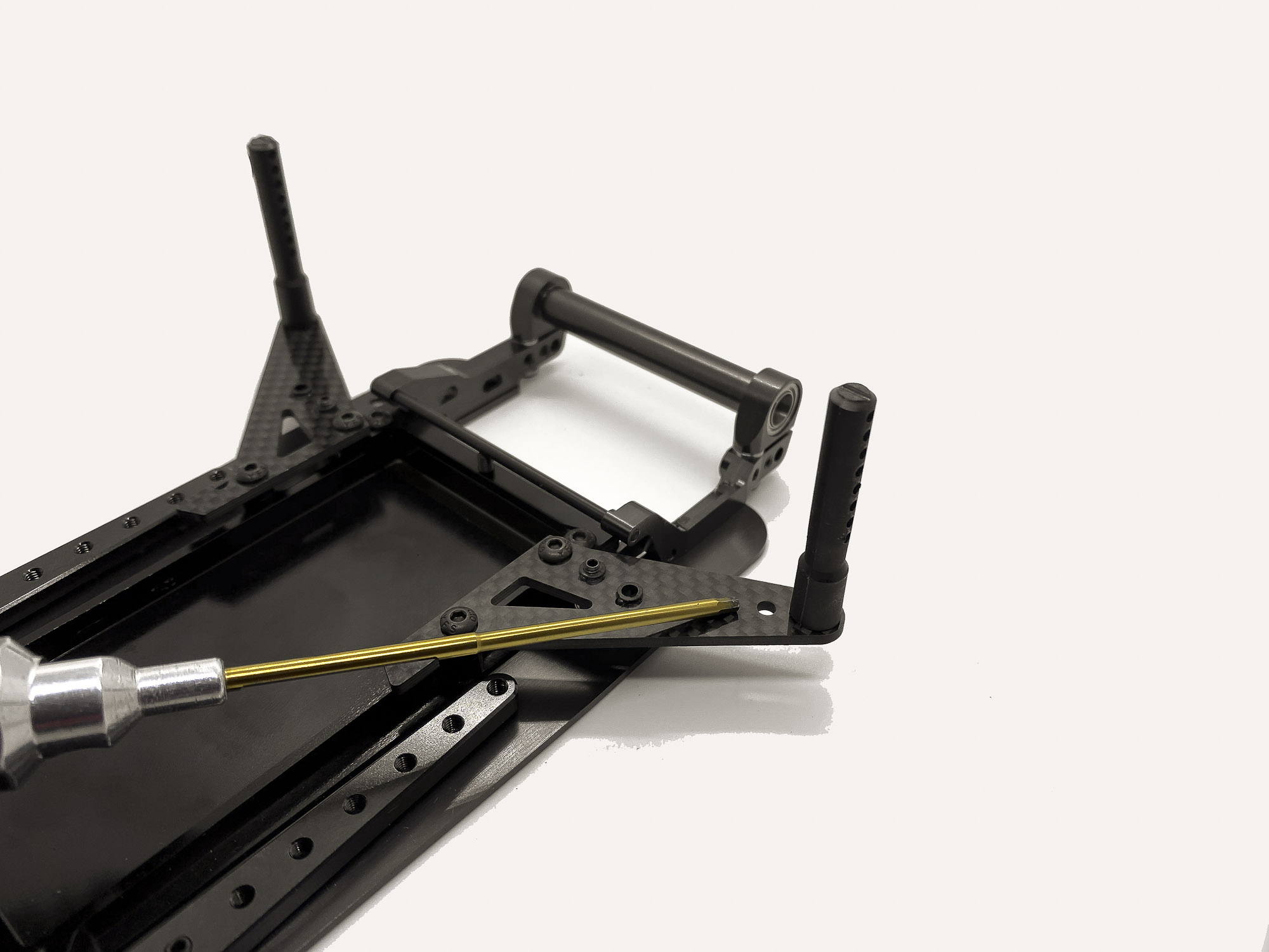
As the Awesomatix history tell - need to be rotary.
Overall only five parts build the unit which everyone was so curious about.
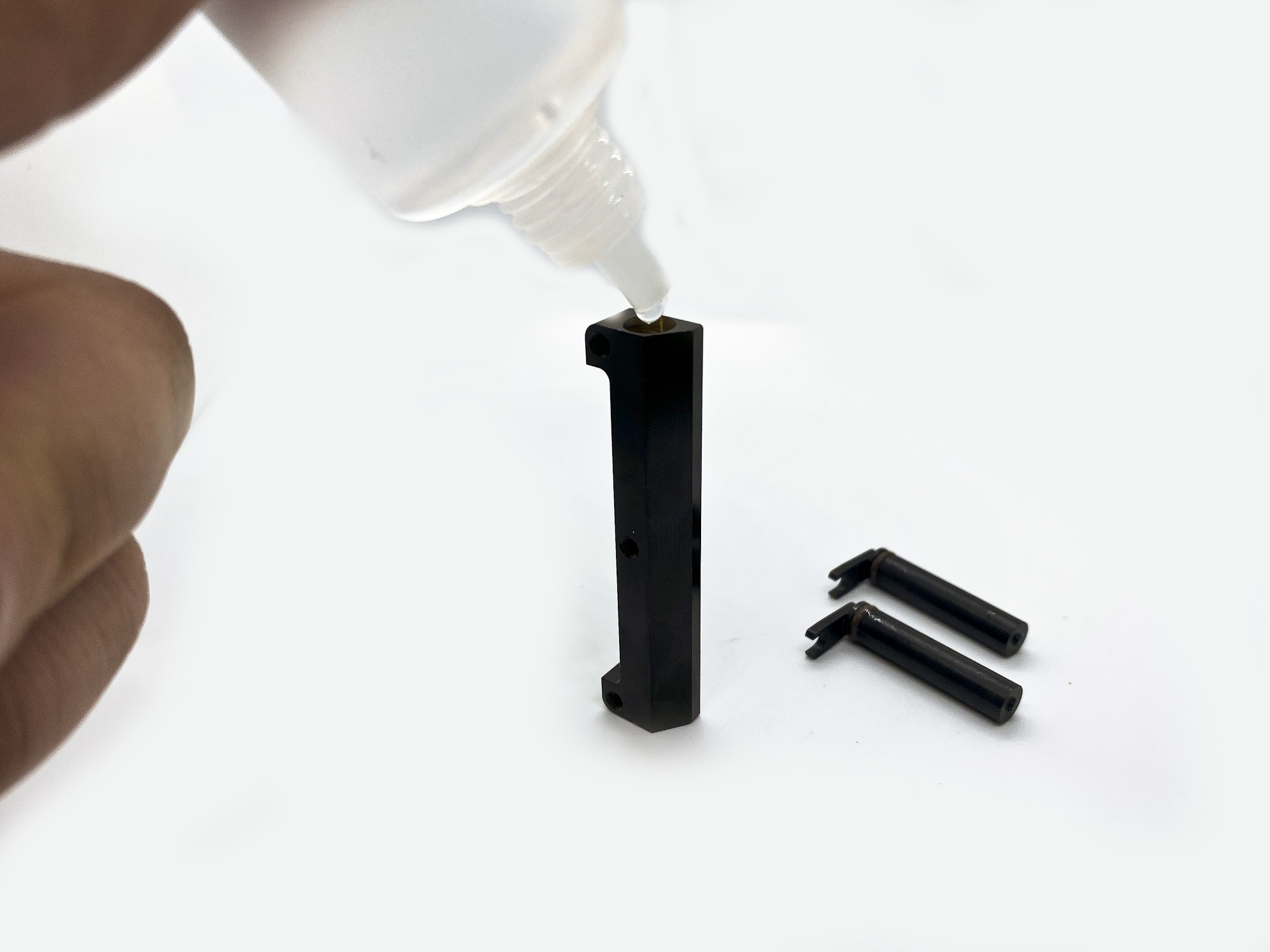
15: Please add a small drop of silicone oil into the groove of ST1202. Also pre-lube the OR153V o-ring before installation to avoid any damage.
16: Build one side first - then when fully finished the second. Put the case vertically on the table and add a small drop of oil into the case.
100.000cst (which is included in the kit) is a good starting point.
17: Now slowly enter the Rotor into the case.
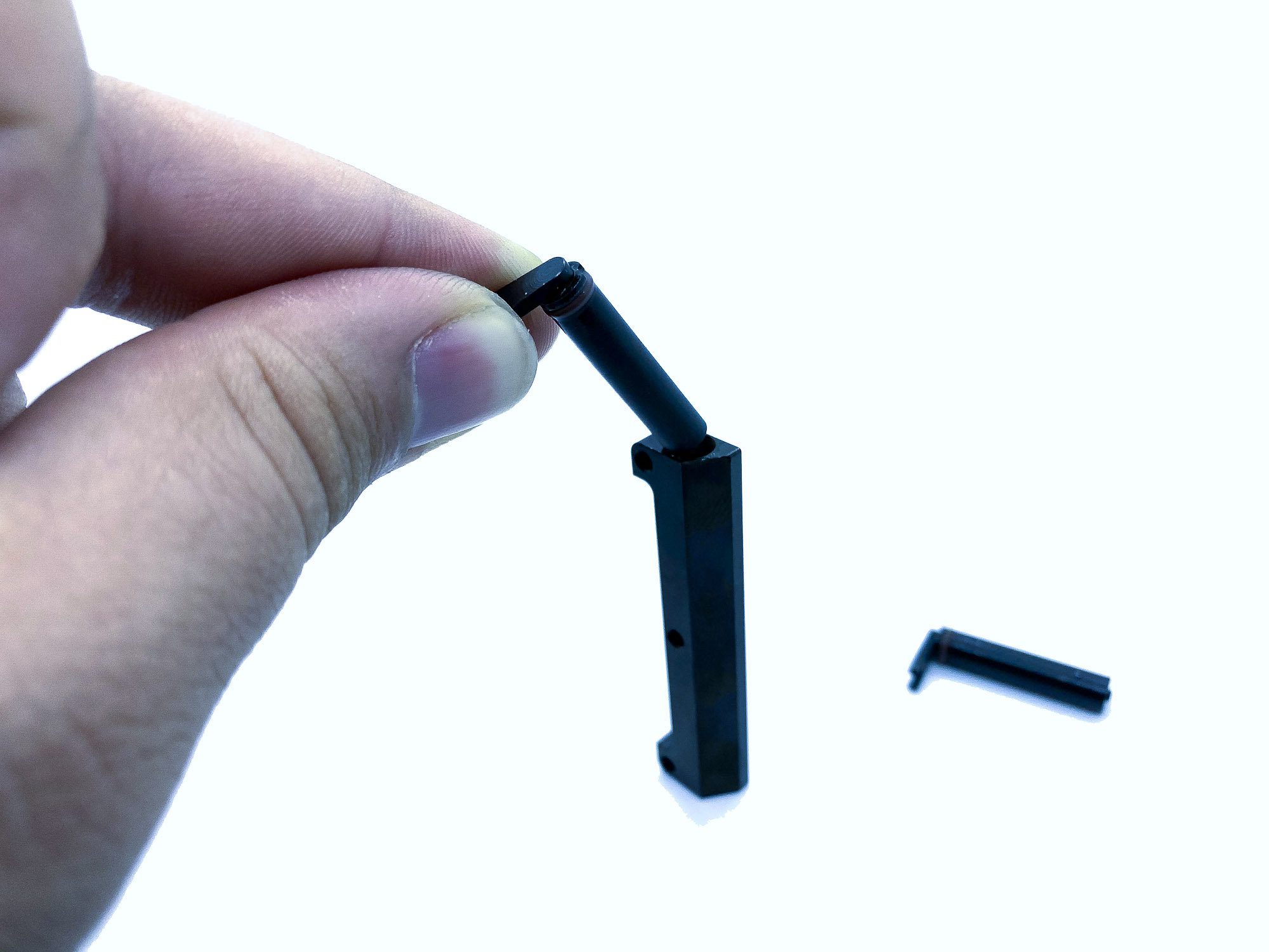
18: Let it sink down by the own weight. You even can push it down gently with your fingers.

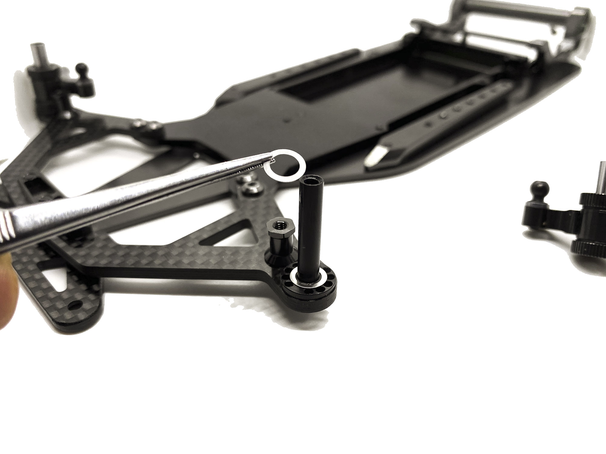
19: To get it fully down - there is a trick mentioned in the manual - by using the Battery o-ring and two M3 screws.
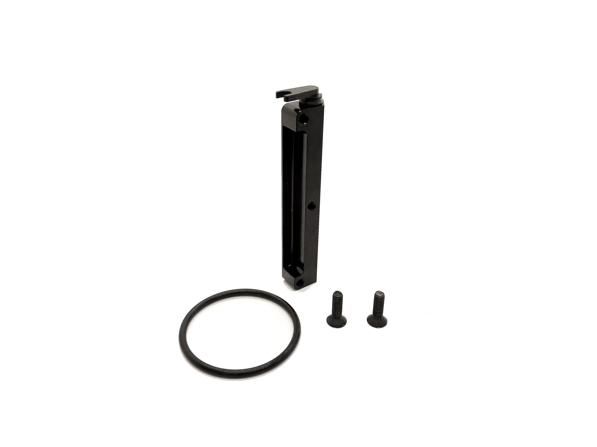
20: Screw the M3 screws from both sides into the thread of the case.
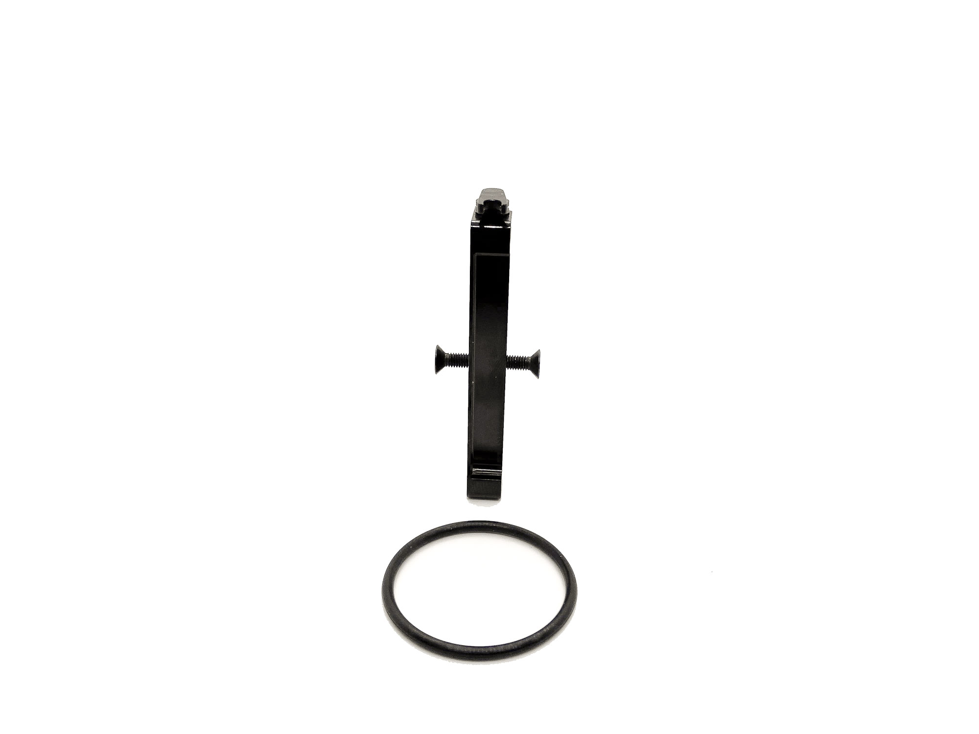
21: Now you can stretch the o-ring over the case and it will push down the Rotor. This will safe your fingers a bit

22: To get the Rotor fully seated its needed to move the OR153V oring a bit, to allow the excesive oil come out. You can use any small needle tool for this. A special recess area can be found in the Rotor for this. TAKE CARE and do not damage the o-ring!
23: The "bleeding" is very important to make sure the rotor is fully flush inside the damper case. It can need some practice.
I always do the bleeding 2-3 times to make sure all is perfect and not to much oil/pressure inside.
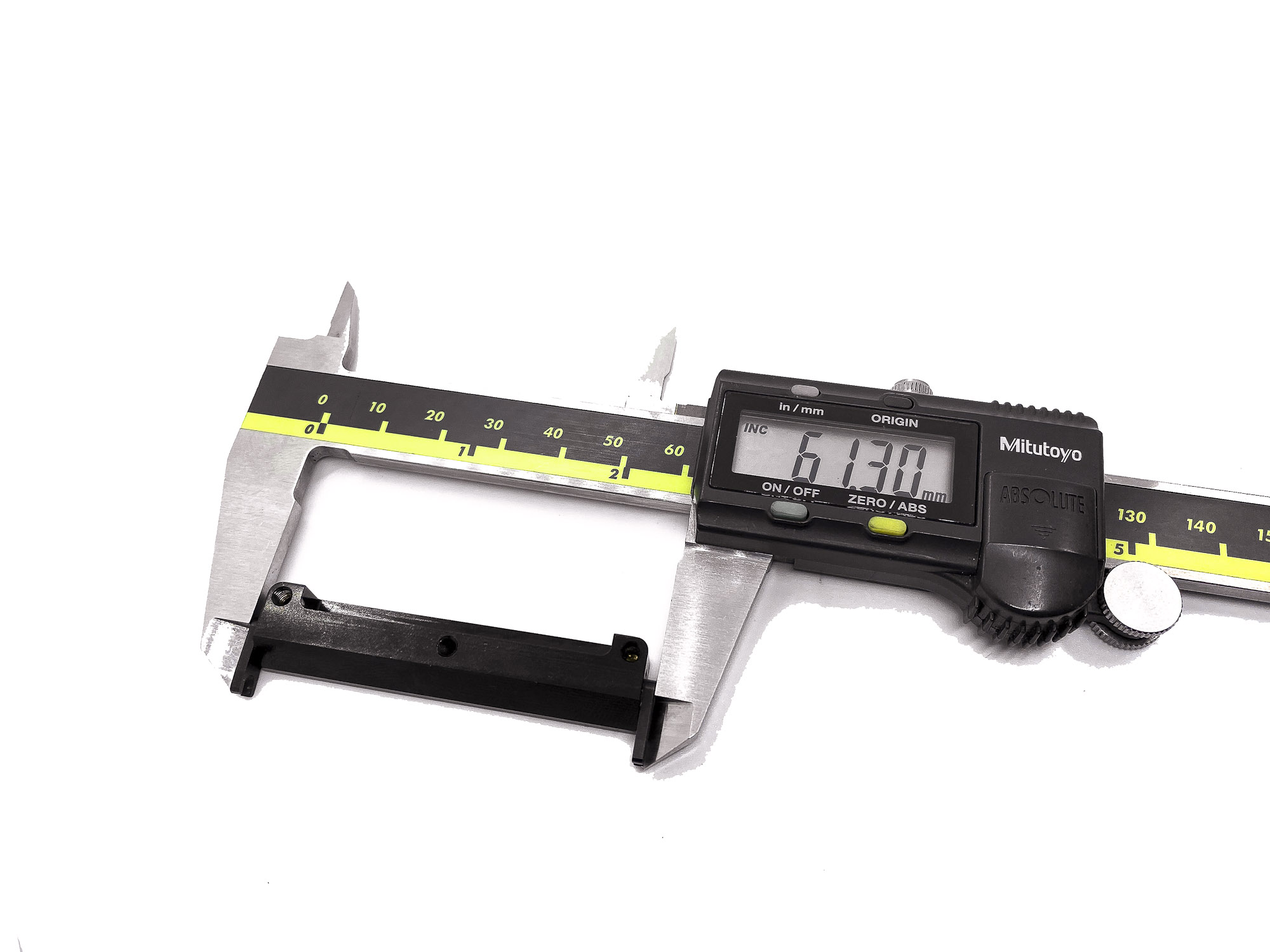
24: After the second side is done - make sure the overall width is in the range of 61,3-61,5mm.
This is important and the final check that the rotors sitting right.
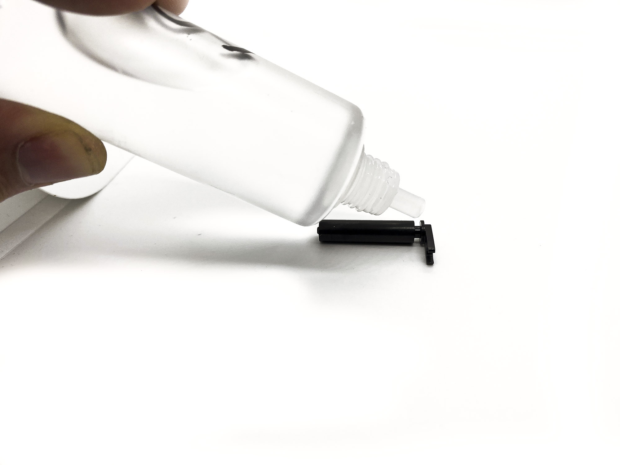
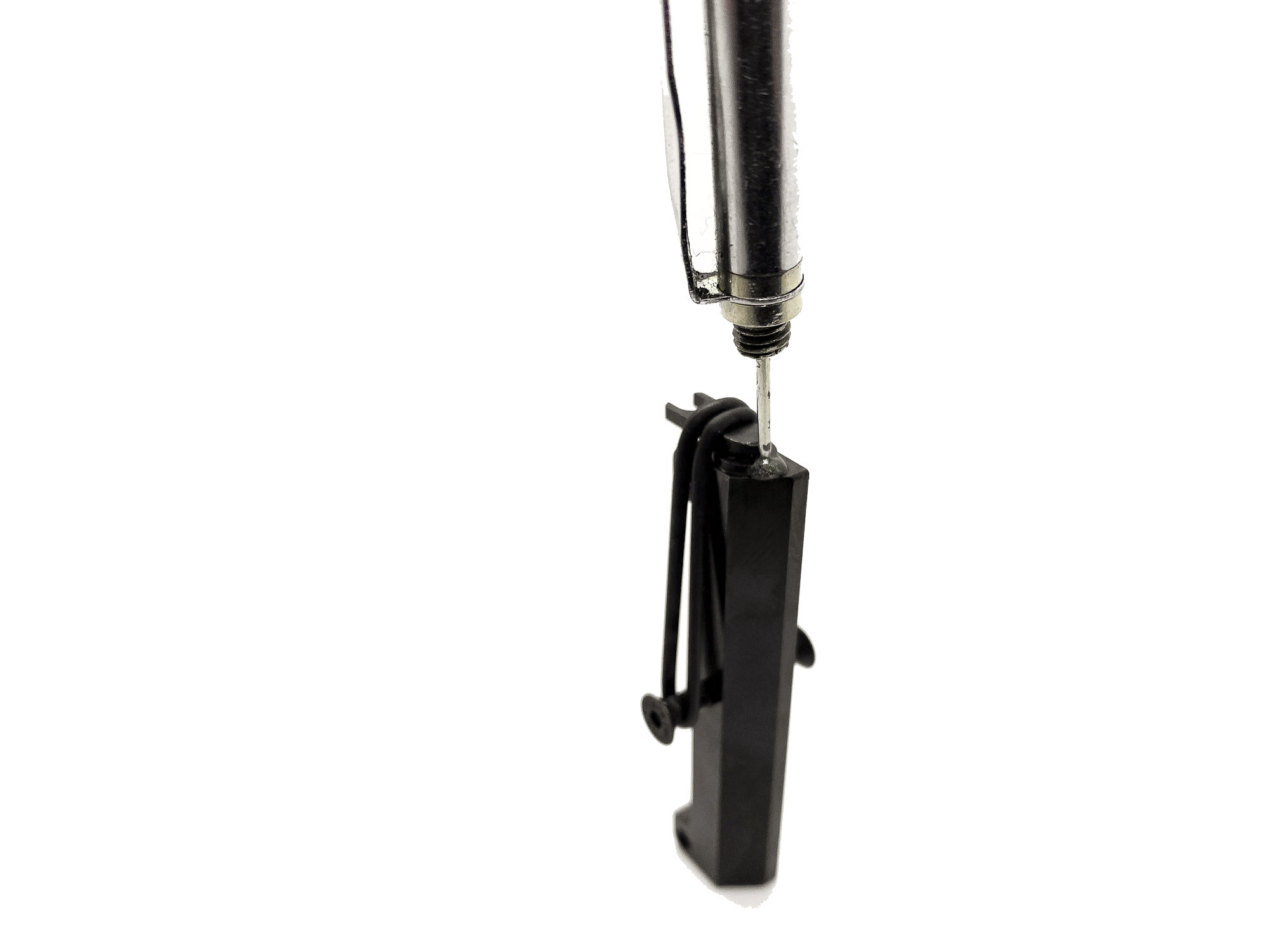
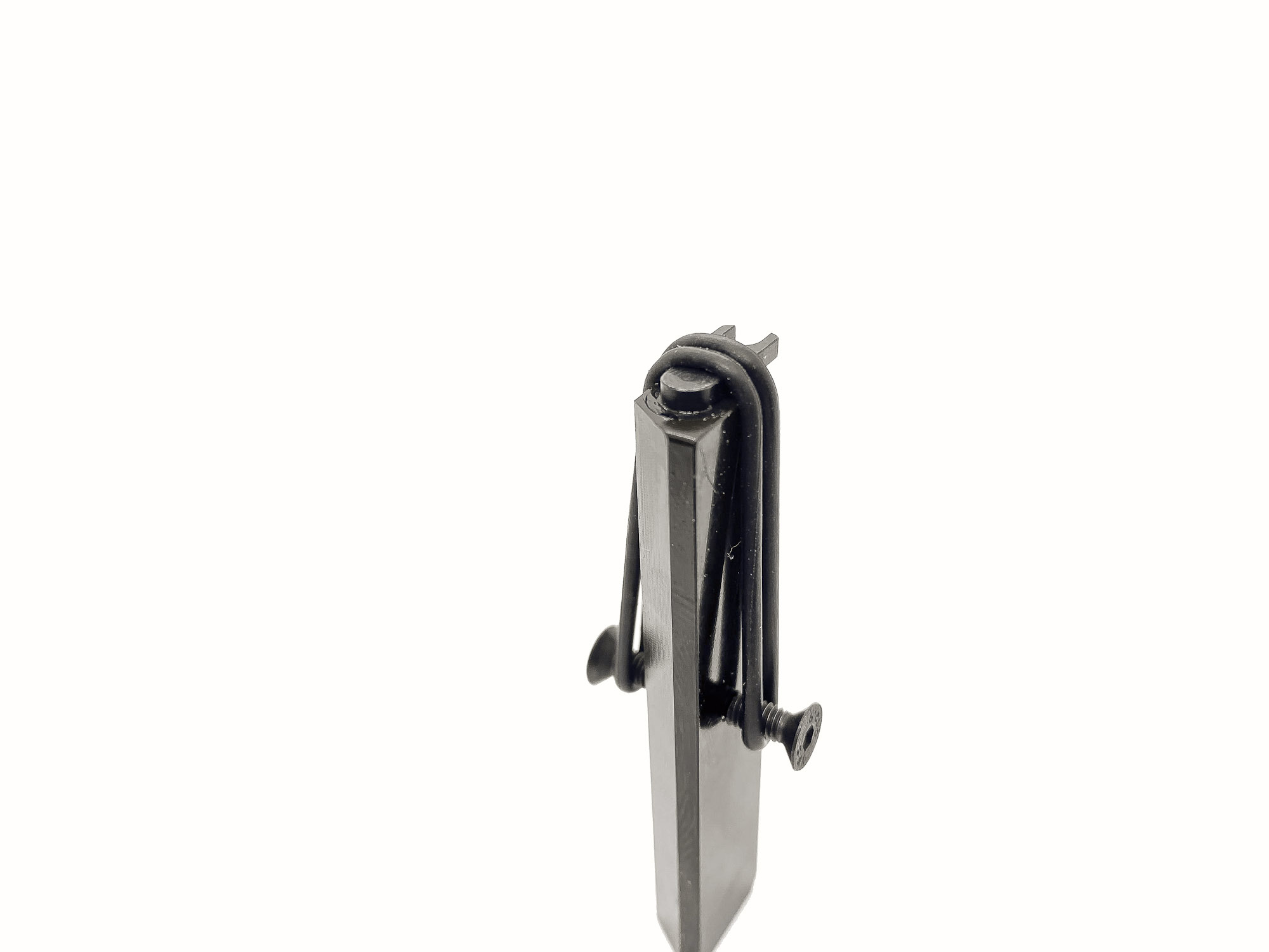
25: The installation of the Damper is very easy by just two screws. For the SS3X10 grub screw we need again a bit thread lock.
26: Just as a very small amount to the thread before screwing it into the Damper case.

27: Left and right Motormounts are different. Make sure to assemble them correctly according to the manual.
28: Both ST1201 Ball Studs need to face to the right.
ST1203 Downstop Rod is sticked into both Motormounts.
29: Four screws connect the Motormount to the chassis.
30: Take care that the "noses" of the Rotor will be connected with the ST1201 Ball Studs.
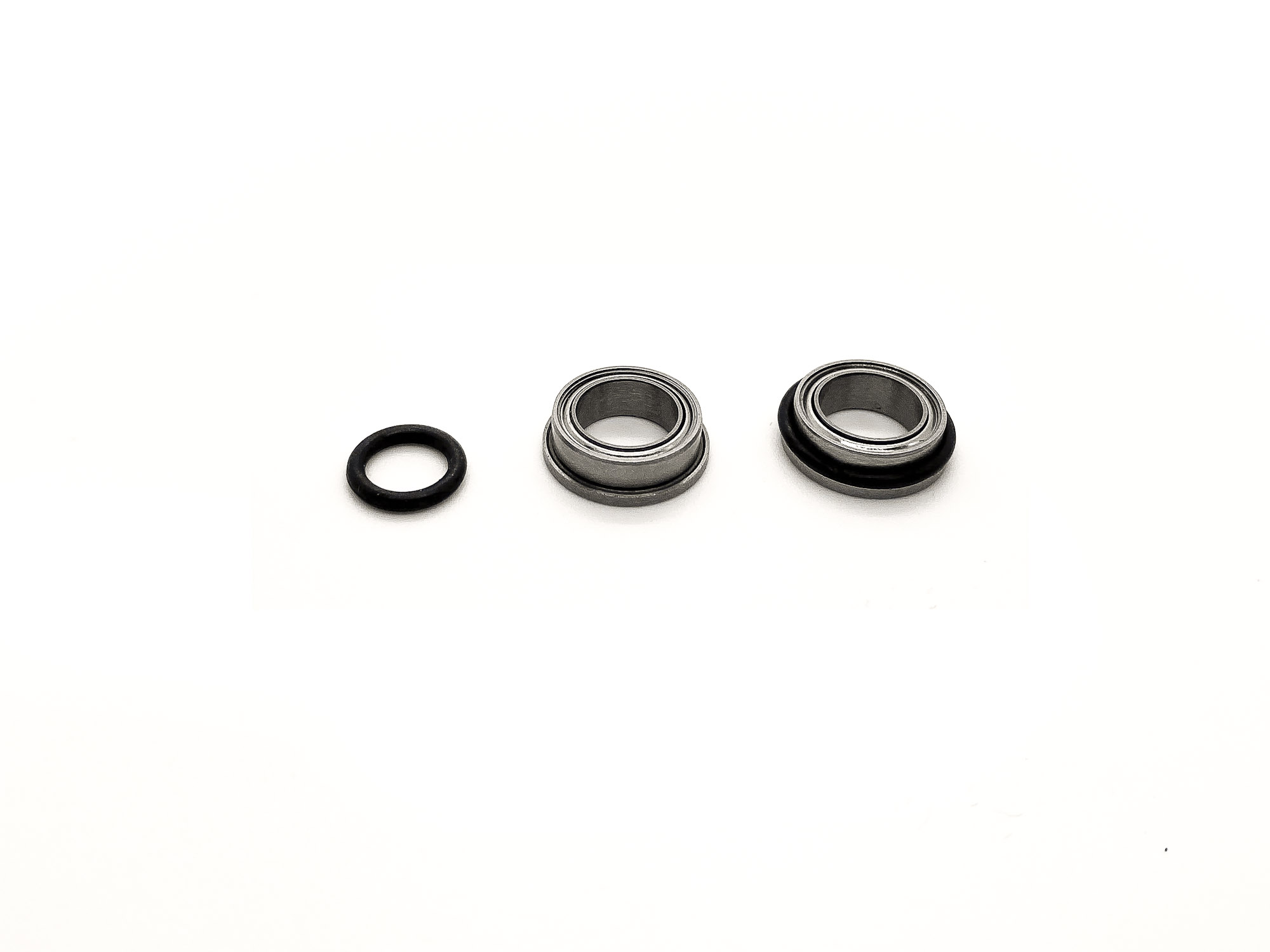
31: The bearings for the rear axle need to be prepared with OR15 o-rings. They allow some elasticity in case of hits to not break the bearing.
Take care at the installation.
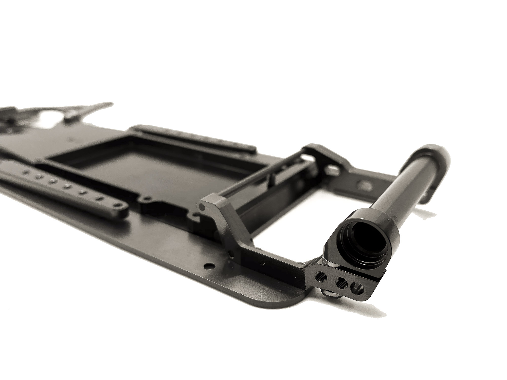
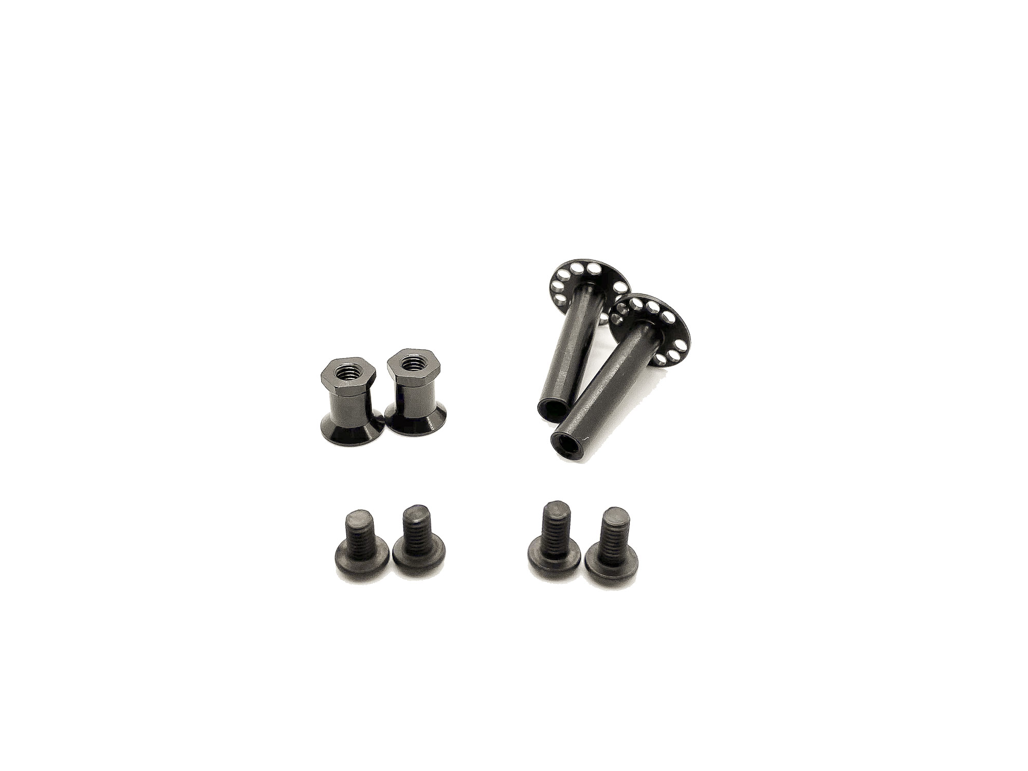
32: All parts for the Rear Beam installation.
IMPORTANT - I recommend to use ALWAYS and ONLY Awesomatix Steel screws and Awesomatix Shims here. Others can be to soft. This is a high load connection and strong materials are needed.

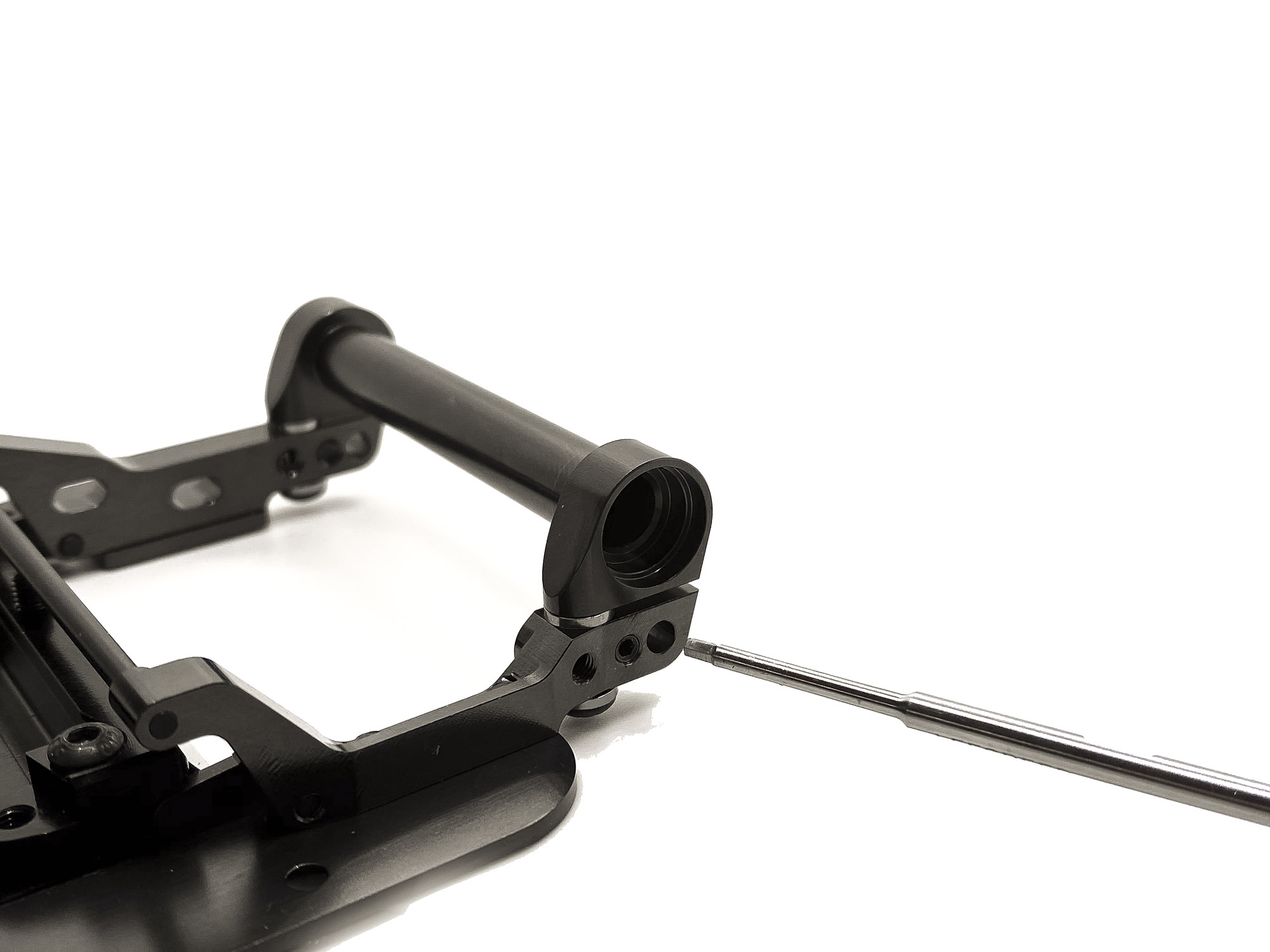
33: By using different thickness shims between the AT1203 rear beam and the Motormounts we can adjust the rear rideheight.
34: Its possible to use either short or long wheelbase.
This will be adjusted by placing the SS3X5 grubscrew in the front or the back hole.
It changes the wheelbase by 1mm!
IMPORTANT - use some soft thread lock for the SS3X5 screw.
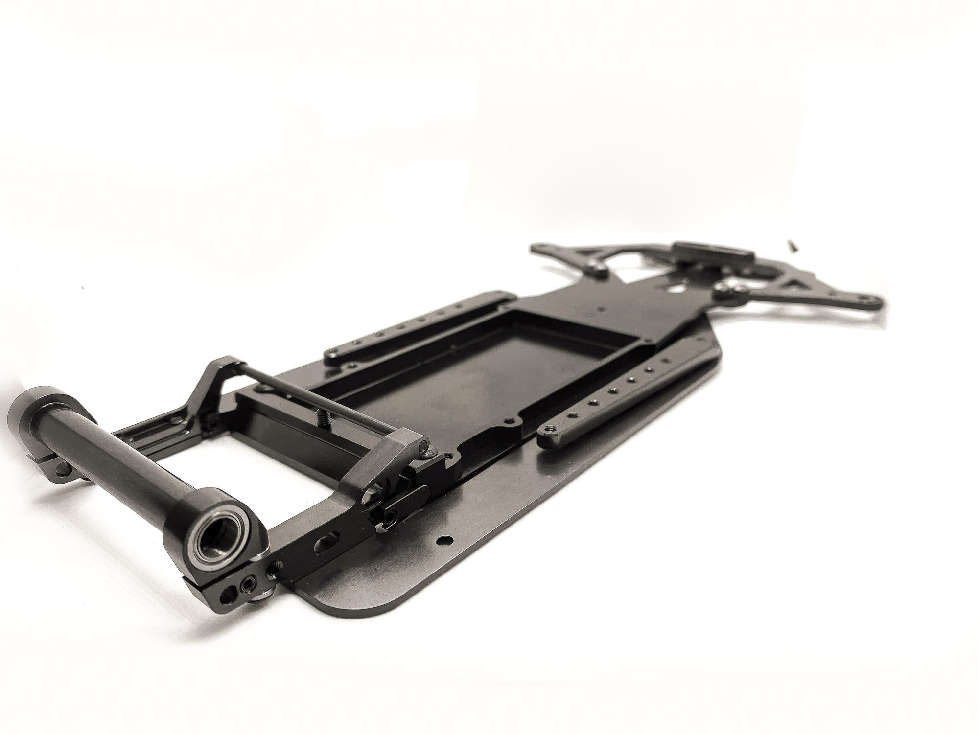
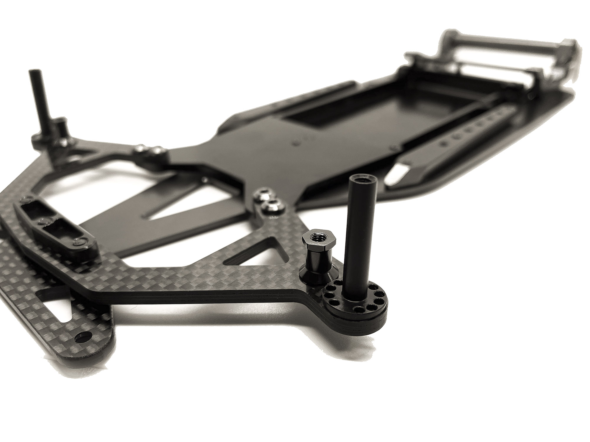
35: What a beauty
Let's move to the front end.
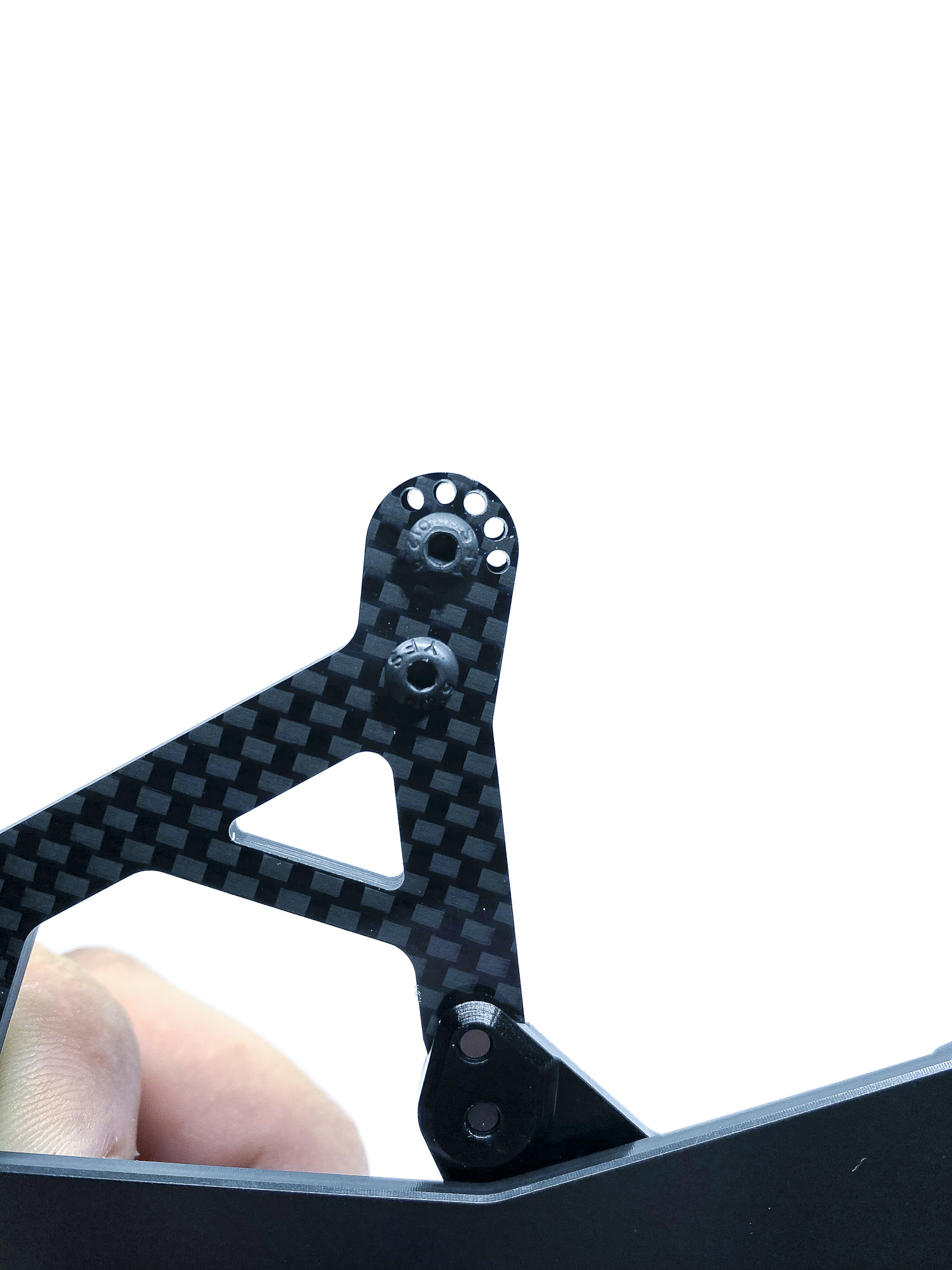
36: Step 14 of the manual is about the installation of the front Steering Block Posts and the Servo Plate posts. It's important to use here only Steel screws!
37: Setting of the front camber is unique and rather easy to do.
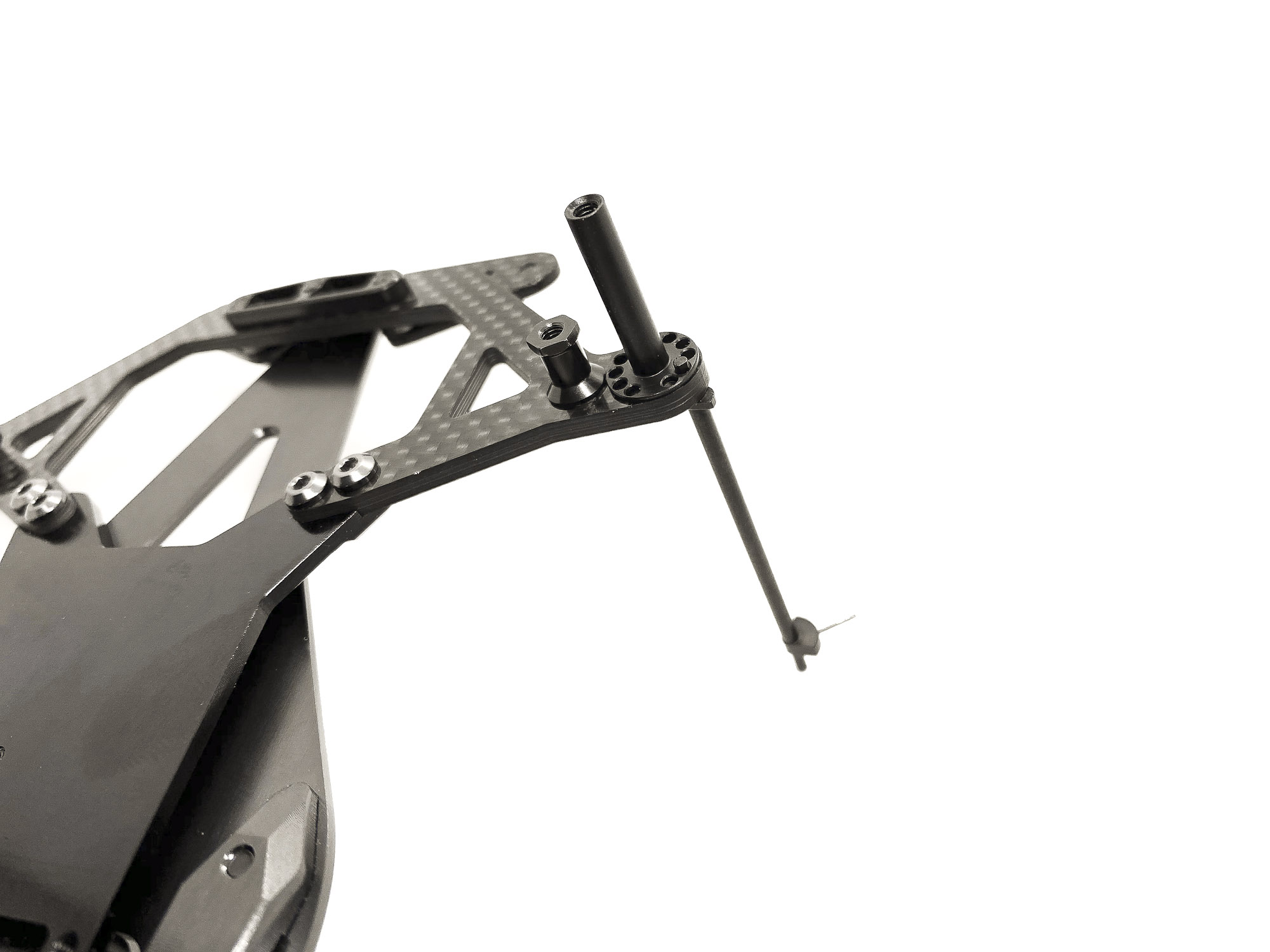
38: You can use the tip of the RHG tool or a 1,5mm tool. Check in the manual which hole you have to chose for the camber you wish to run, and align the post accordingly.

39: Install the screw to fix ST1208 with the alignment tool still in place. This ensure a correct setting.

40: To change camber - just release the center screw a bit and align the ST1208 and the Carbon Suspension plate by the correct hole and fix the screw again. Super easy - super fast!
41: Fancy front end!
42: Next up will be the front steering blocks. Another unique and wonderfull designed piece of the A12.
TIP: for EXTRA SMOOTHNESS - i used some 30.000 and 50.000 sandpaper and further polished the surface of the ST1207 Steering Block Tube.
43: My current prefered setting is to use just ONE OR155SI o-ring at the lower position of the hub without any SH0.1 shim. To lube the o-ring I recommend some light mineral oil or a soft grease. This will be a good initial setup.
Do NOT use silicone oil - it will swell up the silicone o-ring in very short time.

44: Put DT1202 and screw AT1201 gently. IMPORTANT - do NOT overtight it! It causes deformation of DT1202 at thus and leads to bad binding of the steering block.
TIP: I put a super small amount of thread lock there and just screw the nut very gently.
45: Put in the ST1207 Tube in correct orientation.
Shorter part should be on lower side (where the o-ring is placed). Then put DT1202 and screw the nut. Same as before - be gentle and may use some threadlock (highly recommended by me!)
46: To set the front ride height we place SH12S0.2 shims below the Steering Block.
The amount depend of the size of the tires. I use 6pcs with 40,5mm diameter tires to get 3.0mm front ride height.
47: IMPORTANT - make sure the shims surround the ST1207 Tube - but not below!
If this doesn't sit correct the Steering Block Tube will be above the ST1208 Post and cause blocking of steering action!
48: Make sure the post stick out slightly on top.
Then you can be sure all sit correct.
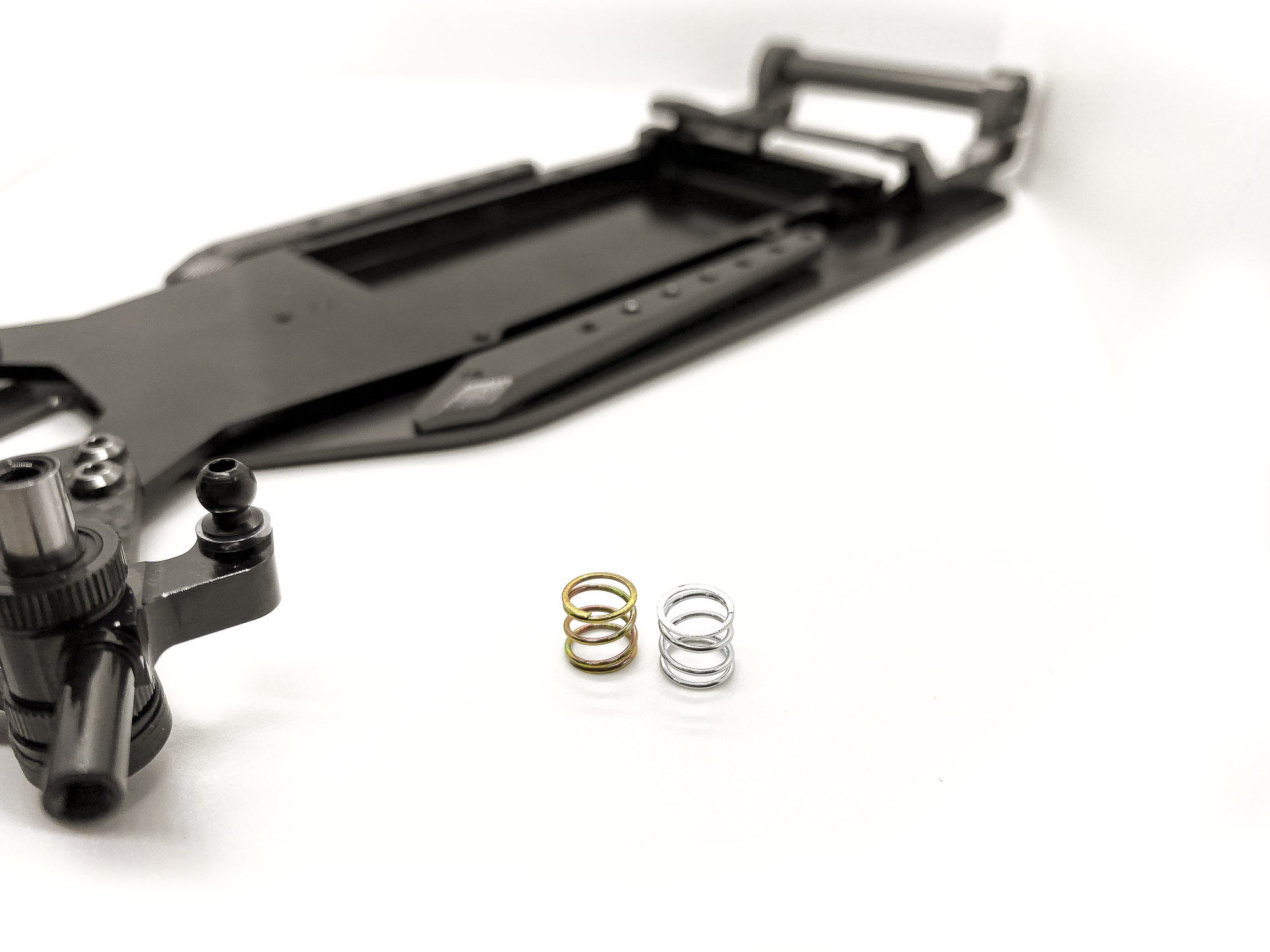
49: With the kit comes two front springs!
Gold = Medium
Silver = Soft
50: Put the SPR12FS (or SPR12FM) on top of the Steering Block. Place another SH12S0.2 shim on top and fix all by using a SB3X5 steel screw.
Make sure the shim surround the ST1207 tube - same as on lower side!
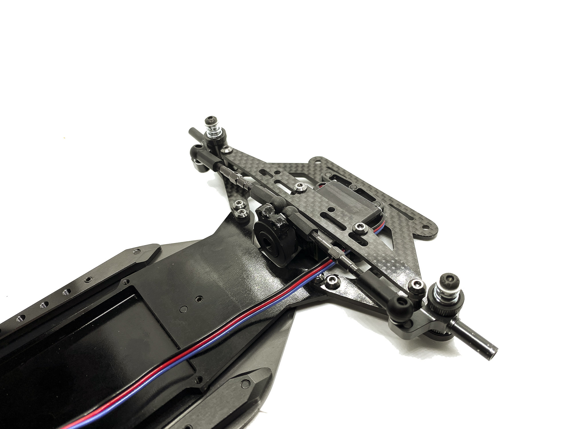
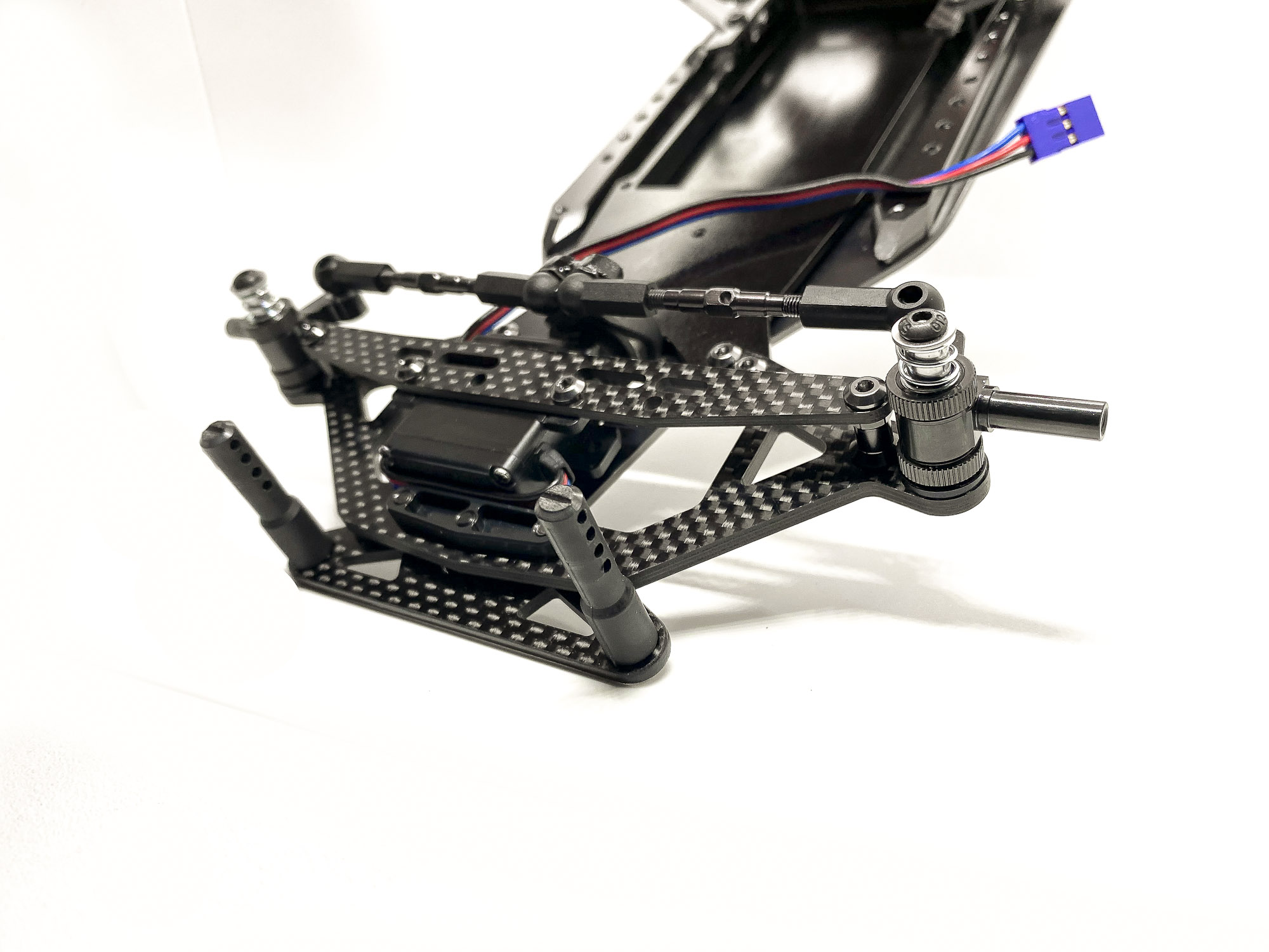
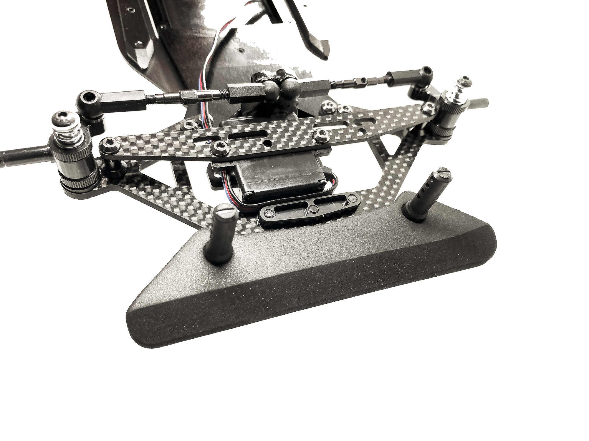
51: Installation of the Servo is next.
If you use a Sanwa Servo you can use the direct mount holes of the Servo to screw it to the carbon holder. In case you have another Mini servo you have to use the included Alloy Servo Mounts. Chose the correct possition/holes according to the manual.
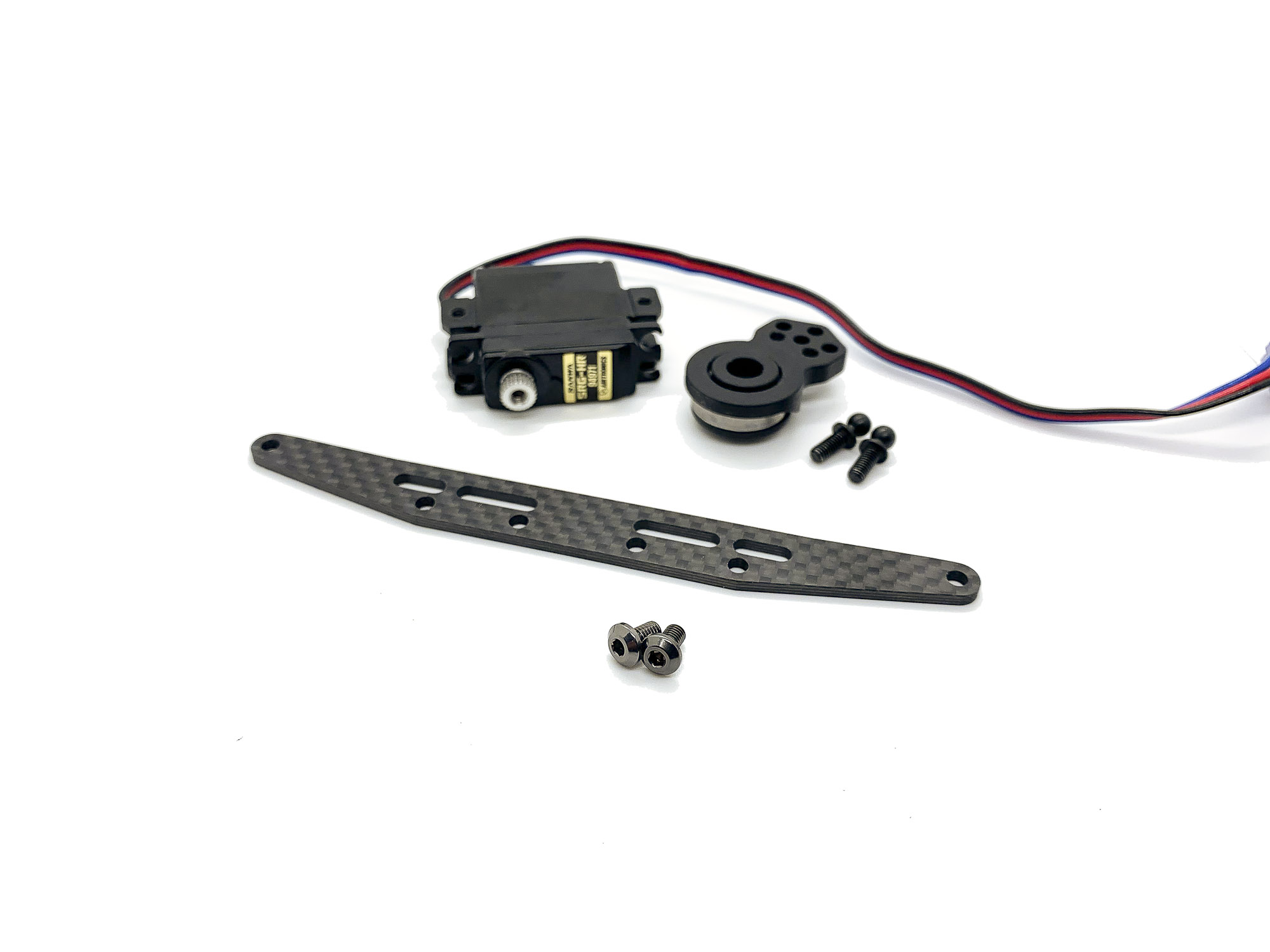
52: Install your Servo Safer (not included) to get the servo ready for mounting into the car.
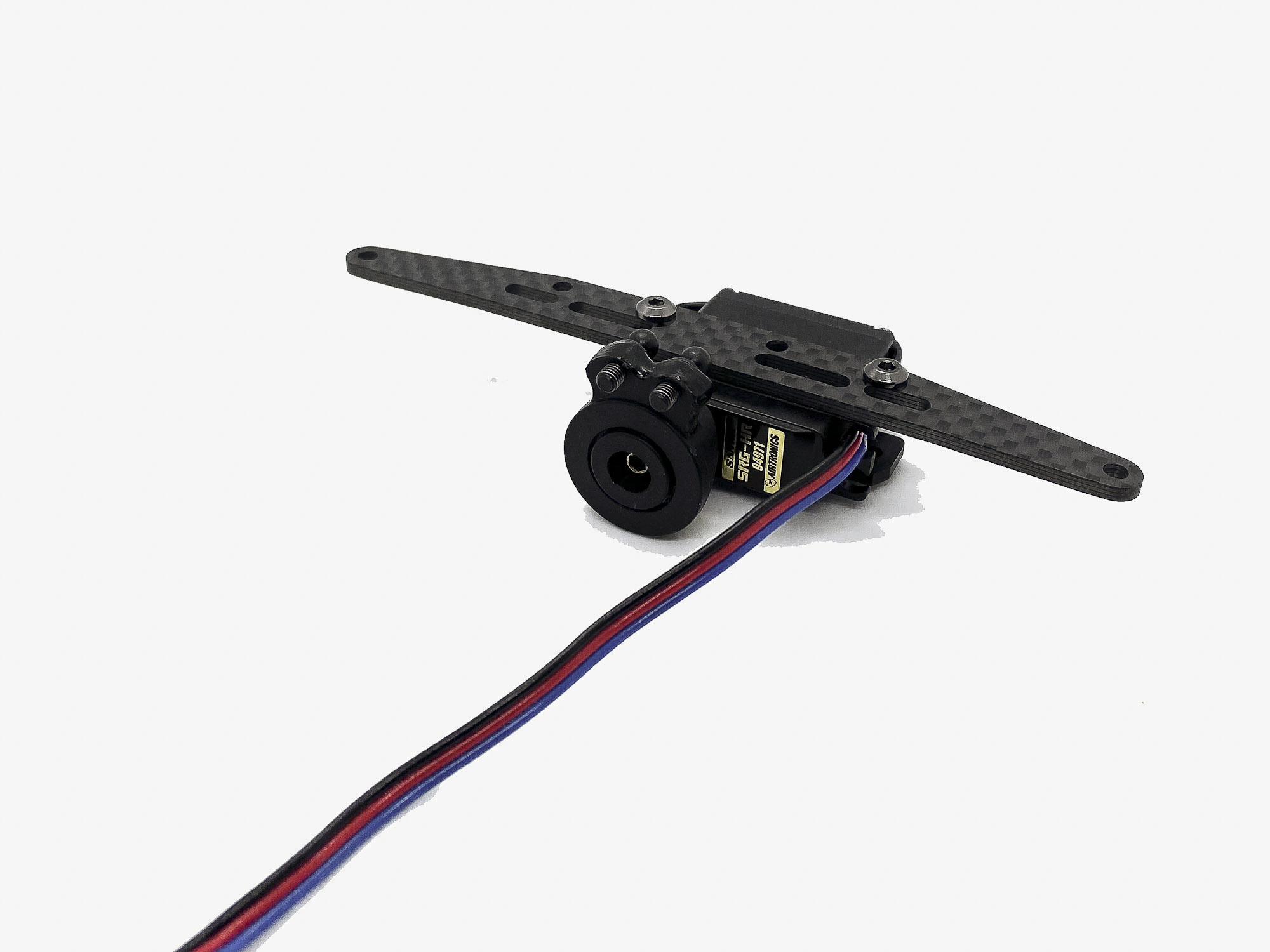
53: Use SB3X5AL screws to mount the Servo Brace on the posts. Again - they will secure it well and prevent any moving of the brace at hits.
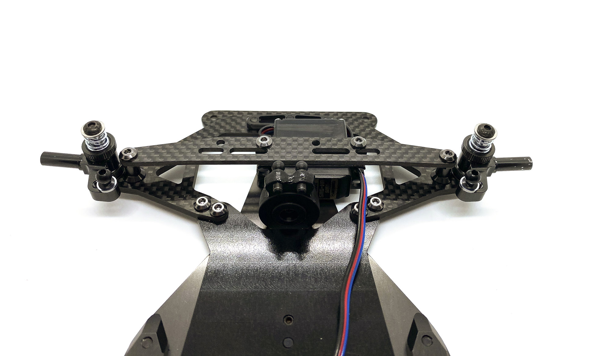
54: Turnbuckles are next. Outside on the hubs are 4.8mm cups and inside on the servo safer 4.0mm.
TIP: For EXTRA SMOOTHNESS you can polish the ballstuds with 2000grid sandpaper.
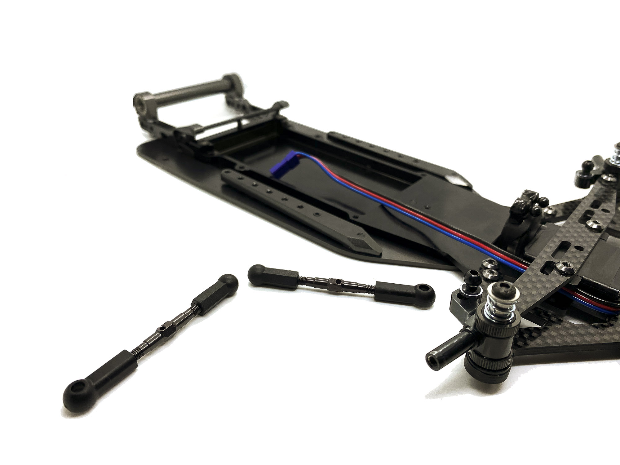
55: Snap the turnbuckles to finish the front end.
56: SIDE WINGS TIME
Super cool looking part in my opinion.
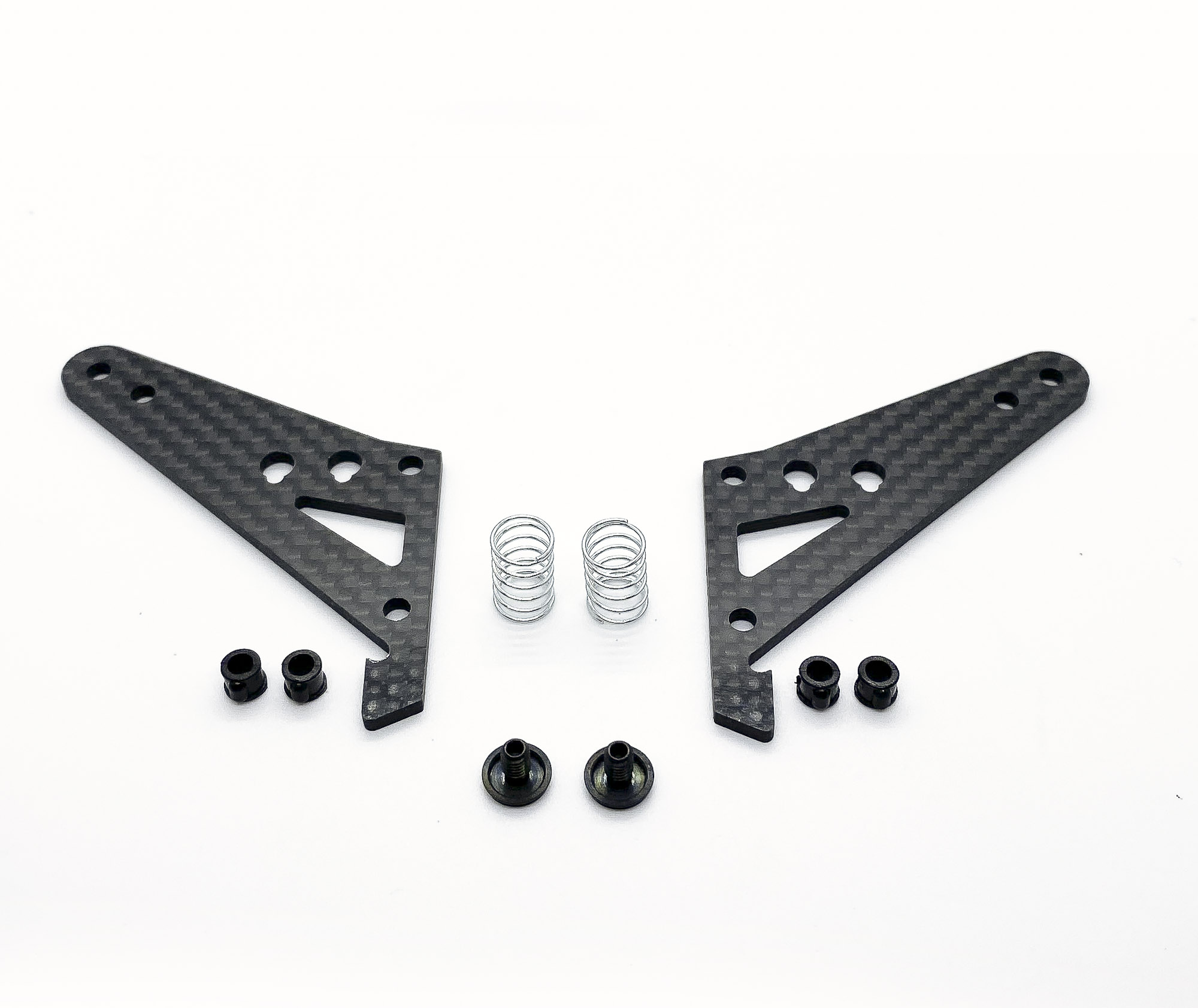
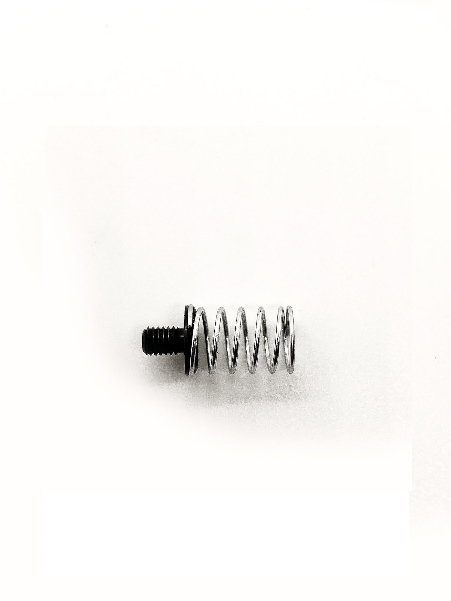
57: Snap the SPR12S0.5 side springs onto the ST1211 steel spring retainer.

58: IMPORTANT - make sure the coil springs are placed correctly and straight like shown on this picture!
59: Push P06-1 collars into the C1203 side wings. Align them correctly before you press them (force is needed for pressing!)
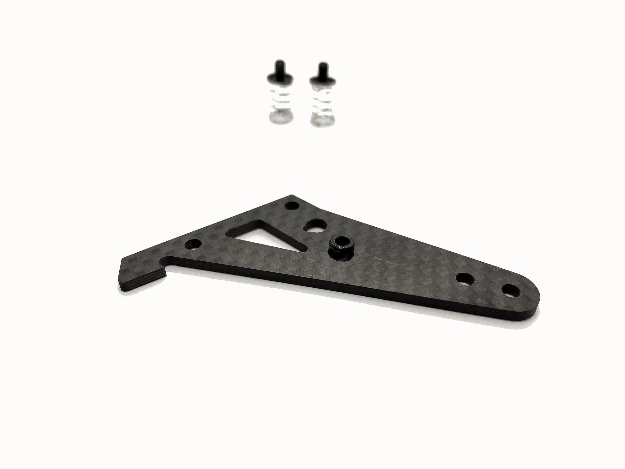
60: Use some CA glue to fix the P06-1 collars.
61: A small drop will be enough!
62: I put the CA on the lower side of the wings - so it looks more clean on topside.
63: Screw the ST1211 into the P06-1. First time is a bit tricky as the thread will be cutted by this.
I use the inner position as initial for the side springs.

64: Parts to install the wings to the battery plate.
(At the time the 4mm shims were not ready - so i needed to use 2x2mm ) In your kit will be four 4mm shims! Also a high strengt area where steel screws are mandatory!
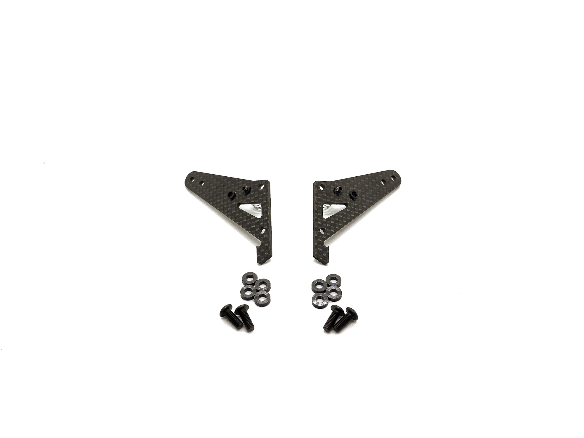
65: So fresh - so clean! Make sure to tight the screws well.
66: Bumper and Bodyposts are next.
The Bumper is very well made and super stiff to support the thin bodyshells well and protect them at crashes.
67: I cut the bodyposts directly before installing. I don't recommend to do this before you have the kit fully build and race ready. Different shells can need different height posts!
Additionally I put a super thin double side tape into the cavity of the Bumper to secure it additionally

68: There are two positions for the rear bodyposts on the wings. I prefer to use always the outer ones (if the bodyshell allow it) as it stiff up the bodyshell more.
69: Fix the front bodyposts with SF3X10 steel screws. Do not use any TI/Alloy screws ever in this area!
70: Install the nice shaped P1215 bumper.
Just press it fully down. Don't forget to remove the foil of the double side tape in advance
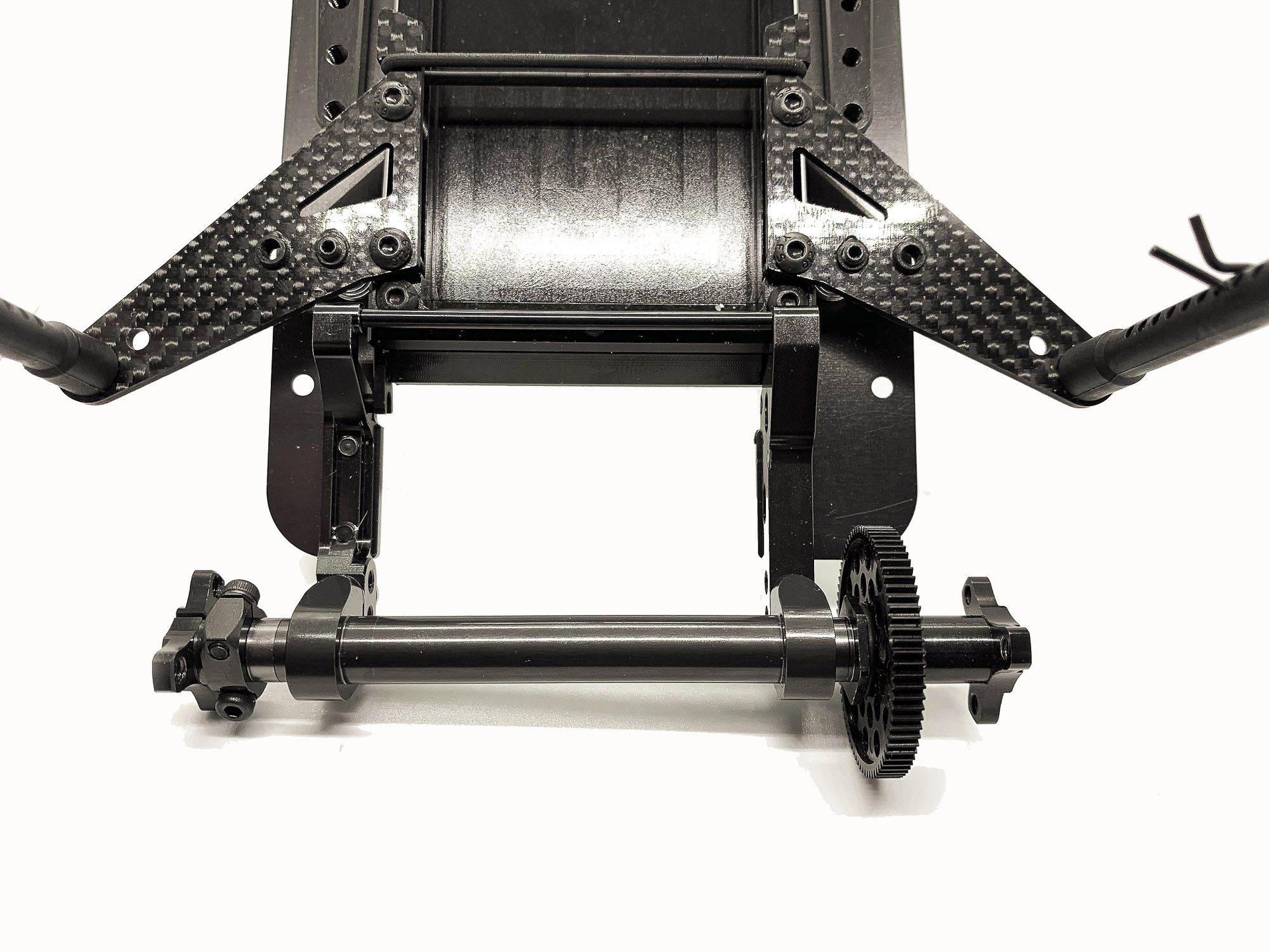
71: Another highlight of the kit at the end of the build.
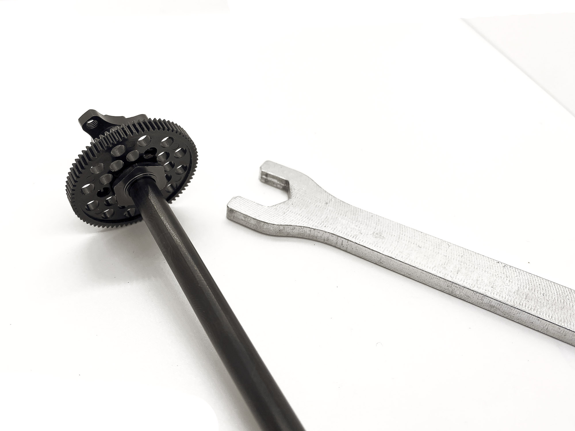
The rear axle. We decided to include a spool axle into the kit as this is recently the most used option by racers at most events.

72: To install the spur gear only ONE nut is needed.
Chose the correct o-ring size according to the thickness of your Spur Gear.
Use a 12mm wrench to tight the nut
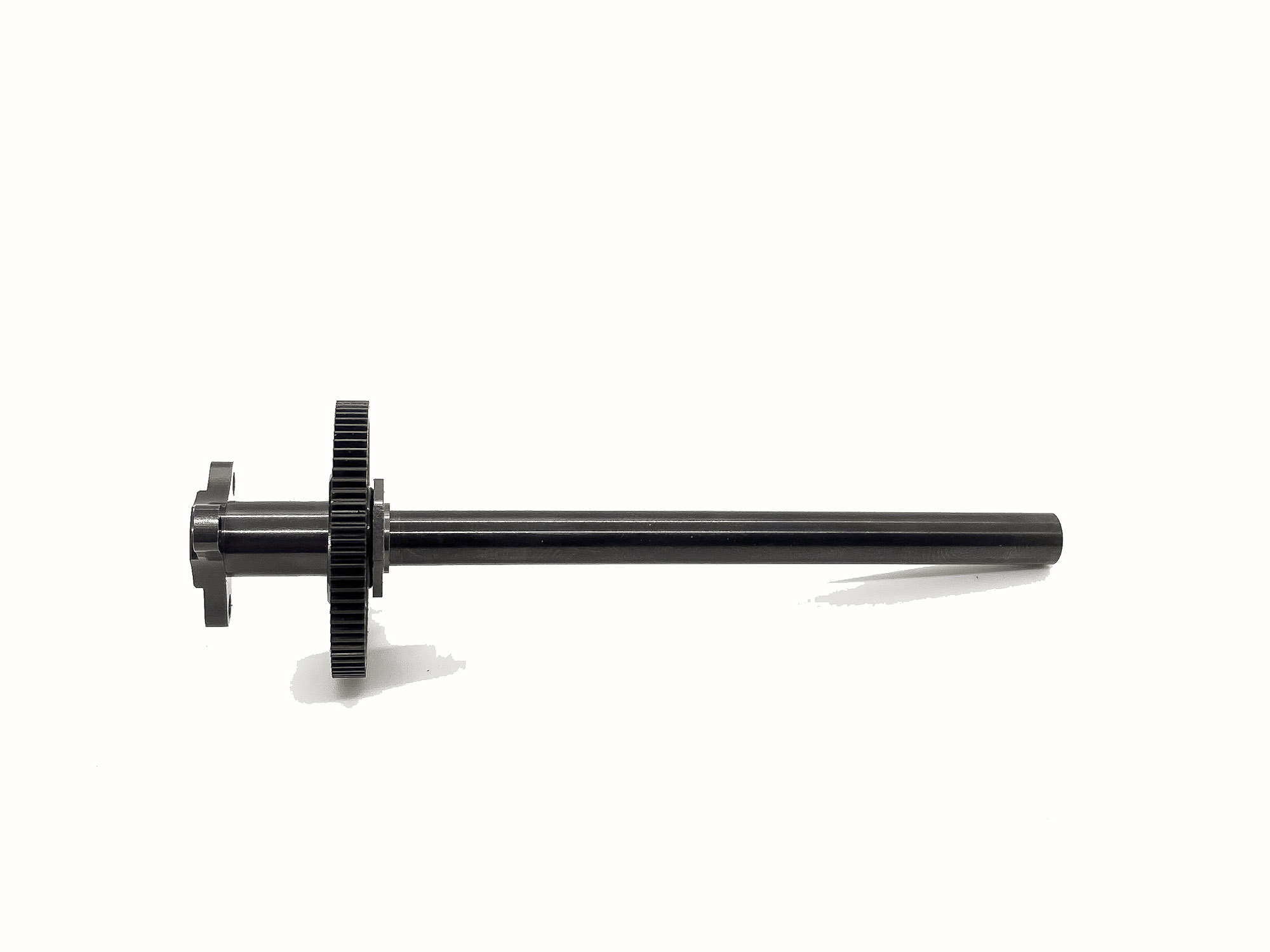
73: The masterpiece of a spool is super light and super strong - by using a solid but hollow steel tube which is precisely pressed into the outer alloy hub.
74: Use the shims accordingly the manual to install the reat axle correctly centered. The left hub uses two SC25X8 screws for perfect axle balancing!
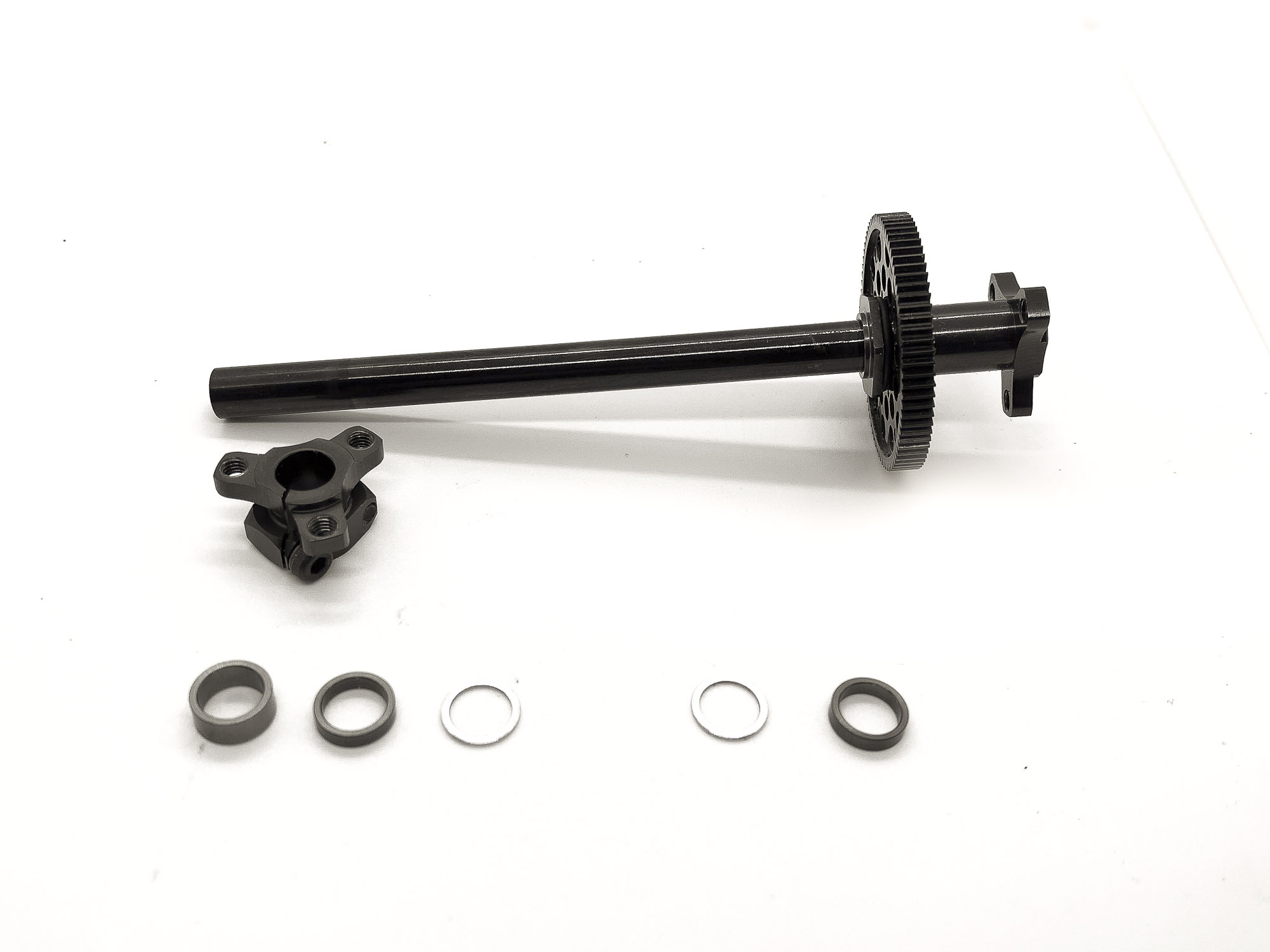
75: IMPORTANT - don't bind the bearings by pressing the hub and axle to strong against eachother at tightening of the clamping screw. 1/10 free play is usefull here!
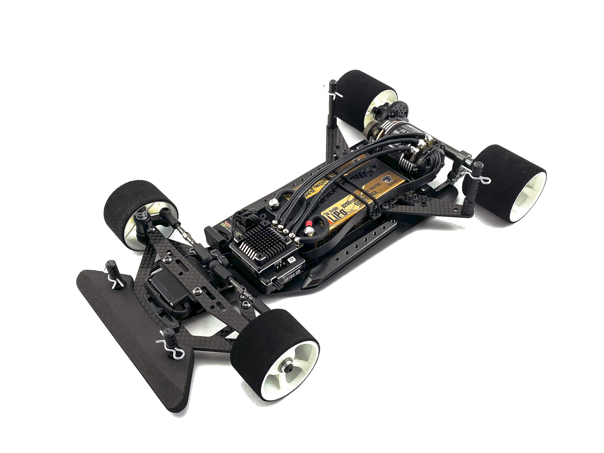
76: Install tires and electronics - set ride height and rear droop -> DONE
Time to hit the track and enjoy the A12.
|