| |
Article ID: 472 |
Pit Pass » Archives
|
[Pit Pass] Revo Performance Set-Up Guide (part 2) |
|
Revo Performance
Set-Up Guide
Steering System & Chassis Attachments |
Welcome
to the second installment of my Revo performance guide. This time, it's
about chassis set-up. I'm going to show you the little tricks that I do
to my Revos involving chassis attachments and radio boxes for better
weight transfer and ease of use. You'll also find simple mods to
greatly improve steering performance and chassis balance.
It's important to remember that paying attention to every little detail on your Revo
Important:
Some of the following procedures require the use of a rotary power tool
for cutting and grinding. Always wear eye protection when using a
rotary power tool.
Steering Mods
Trimming specific areas to attain "full-lock" steering
1. Remove the steering bump stops
This
is a very important step in achieving maximum steering angle from the
wheels. There are two molded bump-stops designed into the Revo lower
hinge pin retainer (part #5343) that straddles the steering
bellcrank. These bump stops limit the travel of the bellcrank, which
was intended to keep newer drivers from over-steering the truck.
With the bump stops ground down (shown above),
and the bellcrank arm beveled (shown below), the steering angle of the
wheels is significantly increased for more overall steering.
2. Bevel the bellcrank
Once
the steering stops are ground down on the hinge pin retainer, the
bellcrank can now travel to the body of the retainer. But, even more
range can be gained by beveling the edges of the bellcrank that touch
the retainer (see photo).
| |
| Left - Grinding the edges indicated in the photo can easily be accomplished with a Dremel™ tool. Right - This photo shows how the bellcrank and the hinge pin retainer meet after the mod. |
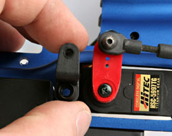
3. Make room for the steering arm
After
substantially increasing the range of the steering bellcrank, the part
of the arm that connects to the servo will now interfere with the
outside of the hinge pin retainer, where it mounts to the bulkhead (See
photo). Remove material, as needed, to get full range from the
bellcrank (left to right). You shouldn't need to remove any more
material than what is shown in the photo.
4. Eliminate the interference between the rod ends and the bulkhead
When
the suspension is fully extended, the inner rod ends on the steering
links may rub against the bulkhead halves in the areas indicated below.
This can slow steering response and limit range when under
acceleration. Be careful not to over-grind this area because this is
where the two rear suspension pins are captured for the front
suspension arms. Use the photos as a guide.
5. Remove the pivot ball dust boots
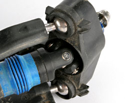
This
is very minor, and normally doesn't need to be done. But, if you've
completed all of the steps above correctly, then chances are the boots
are now keeping the hub carriers from bottoming out against the ball
shafts.
To get maximum angle from the hub
carriers, the boots must be removed. Make sure to check the pivot balls
and hub carriers regularly for dirt or binding. There should be no
problems with the operation of the pivot balls when routine maintenance
is performed.
6. Install a longer steering arm
After
all of the above modifications are performed, the steering system will
allow an extra-long servo arm to be mounted onto the steering servo.
The longer servo arm will provide the extra range needed.
I
recommend the use of a heavy-duty servo arm. Check with your local
hobby shop or your radio manufacturer for what's recommended for your
particular servo.
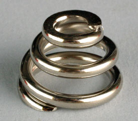
7. Traxxas heavy-duty servo saver spring (part #5344x) / Pro-Line™ aluminum steering arm
I
use the heavy-duty servo saver spring in all of my Revos. The HD spring
provides more steering authority and keeps up with the higher demands
of track surfaces that offer extreme traction. It's also best if the HD
spring is used with a strong high-quality servo. The stronger spring
may not give enough for weaker servos. This may lead to servo failure. |
| |
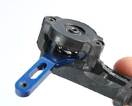
| You
can also check out the Pro-Line #6037-00 aluminum steering arm for the
Revo (right). I haven't actually broken the stock steering arm, but
this Pro-Line aluminum steering arm will ensure that nothing like that
will happen when using the extra-stout servo saver spring and a
high-powered steering servo. |
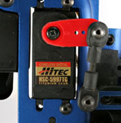
8. Upgrade the steering servo
| The
twin stock servo set-up is great for bashing and novice-level racing,
but when facing the demands of competitive off-road racing, a
high-powered/high-speed servo is what you'll need to transition from
left to right-hand corners quickly. I use the Hitec HSC-5997TG servo. |
I
recommend using a servo with at least 110oz. of torque, so only one
servo can be used. This will save a little bit of weight and will leave
you the choice of mounting the servo on the left or the right-hand side
of the chassis.
I place my steering servo on the left side
(drivers side). This helps balance the chassis after removing the
EZ-Start electric starting system from the engine.
Weight balance
Removing
weight is common for making a more responsive race truck. Sometimes,
removing too much weight can cause the truck to be unstable. I've found
that 7.5 to 8.0 pounds is a great range for the Revo. This weight range
offers a good balance between response and stability.
Most
everyone knows that removing unnecessary items such as the starting
system, and the reverse components will knock off the ounces. However,
when you get down to less than eight pounds, you may try moving some of
the weight around to different areas of the truck. This will change the
feel of the truck, and better suit your driving style or track
conditions.
I measure the front to rear weight bias on all of my race vehicles. So much can be gained from correct balance.
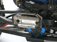
Removing weight from specific areas

There
are different ways to achieve desired results. There are many items
that can be removed or swapped with lighter versions of the same item.
You may choose to replace steel components with aluminum counterparts,
like the pivot ball (#4933X) in this photo. It's a good way to shed
some weight in a specific area. For example, if you want to reduce the
weight at the rear of the chassis, but not at the front, you can
replace just the rear pivot balls with a set of aluminum pivot balls.
This also works for items like toe links and push rods.
Strategic weight placement
Sometimes
you need to get just a little bit more out of your chassis. Adding
weight to specific areas can help. This photo shows where I mounted two
ounces. of lead (tire weight tabs) to the front skid plate. This helped
with steering and improved handling when using engines that generated a
lot of torque. This also helped keep the chassis flat off of high-speed
jumps.
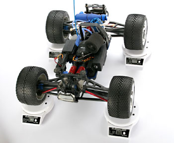
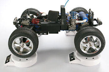
Weigh your truck
Keeping
track of your truck's weight will give you a good idea of what needs to
be done to get your chassis where it needs to be. The scale set (below)
is an elaborate one and not totally necessary to get the information
you need. Multiple digital scales like these can be pretty pricey. All
you really need is one scale.
When only using one
scale, place the scale under one corner at a time, while the other
three wheels are propped up by a solid object of the same height as the
scale. This way you can measure one corner at a time, and then total up
your readings.
A
good starting point for weight bias (front to rear) is 47%-front bias,
and 53%-rear bias. My truck in the picture totals out at just over
eight pounds, with a front weight bias of 47.8%, and rear bias of
52.2%. The more you increase the front bias number, the more steering
you will find.
Calculating weight bias (front to rear)
(total of both front corners) = total front weight (F)
(total of both rear corners) = total rear weight (R)
(F) + (R) = total truck weight (T)
(T) = 100%
(F) = n (front weight bias)
cross multiply (T)n = (F)100
n = (F)100/(T)
Now, let's do this using a sample scenario with actual numbers from an 8 pound truck:
weight of front = 61oz.
weight of rear = 68oz.
61 + 68 = 129oz. total weight
129 = 100%
61 = n
cross multiply 129n = 6100
n = 6100/129
n = 47.29% (front weight bias)
Once
you start recording changes to your truck's weight bias, you can use
those results as reference for when you decide to make a change in
set-up, or install aftermarket components onto your truck. You can see
what affect the changes made to your bias, and better understand why
your truck may have felt different on the track.
Radio installation and RX box mods
Here are few things you can do to better secure your radio boxes and to make working with them a little easier.
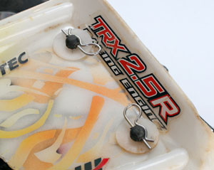
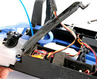
Zip tie radio the box hinges
I
made hinges for my lower and upper covers for my receiver box. This
allows the covers to be opened to access the receiver, battery, switch,
and etc. without having to separate them from the box.
They
also secure their respective ends to the radio box, so you don't have
to worry about the covers popping off from a hard crash or jump
landing.
RX cover |
|  |
Drill
the holes close to the pivot points of the covers (click on photos for
larger view). Use small zip ties for the hinges and be sure to make the
holes large enough for the ties being used. After drilling the holes,
insert the zip ties through the holes, and cinch them up (not too tight
at first). Make sure the lids close securely, and open all the way to
access equipment.
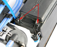
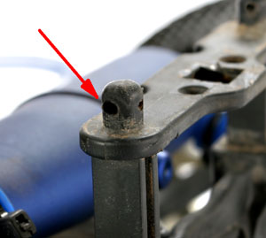
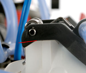
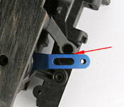
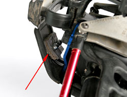
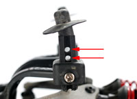
Extra antenna tube security
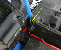
Here's
a little trick that I use to keep the antenna tube from loosening and
pulling out. Cut a slot (yellow arrow) right next to the groove that
the tube slides into. Now, drill a small hole (red arrow) to the other
side of the antenna slot about a 1/4-inch down from the top of the tube
entrance.
Insert the tie through the hole and around the tube
slot. After inserting the antenna tube into the slot, cinch down on the
zip tie. This will tighten the slot around the tube, making it much
more difficult for the tube to come out.
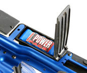
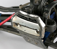
Extreme radio box mods
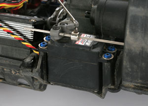 Left
- Here is an example of removing all excess material from the throttle
servo box. This is pretty extreme, but it does clean things up a little
bit, and makes getting to the throttle servo and linkage much easier. Below - This is an extreme modification to the RX box. All but the battery compartment was trimmed off to reduce weight and lower CG.
Left
- Here is an example of removing all excess material from the throttle
servo box. This is pretty extreme, but it does clean things up a little
bit, and makes getting to the throttle servo and linkage much easier. Below - This is an extreme modification to the RX box. All but the battery compartment was trimmed off to reduce weight and lower CG. 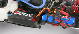 The receiver is placed inside of the battery compartment area, while the battery was moved up front for more front weight bias. Important:
This photo is to show what can be removed from the box only. It's very
important to cover all areas of the receiver box to prevent moisture
and dirt from entering. This set-up is fine for dry conditions, but I
don't recommend this mod to be run in wet conditions.
The receiver is placed inside of the battery compartment area, while the battery was moved up front for more front weight bias. Important:
This photo is to show what can be removed from the box only. It's very
important to cover all areas of the receiver box to prevent moisture
and dirt from entering. This set-up is fine for dry conditions, but I
don't recommend this mod to be run in wet conditions.
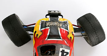
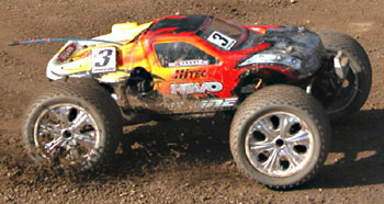
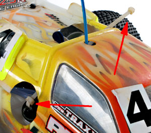
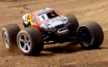
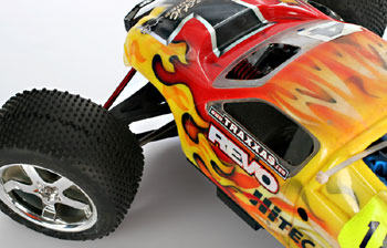
Body mounting
Here's
two of my favorite body styles for the Revo: The Traxxas S-Maxx body
(#5112X), and the Pro-Line Crowd Pleazer body (#3144-00). I'll use
these two bodies to show you a few things that I believe are important
for racing.
|
| Here's
both the S-Maxx (above), and the Crowd Pleazer (below) in action. These
are the two most commonly used body styles on my Revos. I prefer a
"fastback" style not only because I think they look more "racy", but
they also offer extra protection to the engine and exhaust system vs.
standard bed designs. |
|
Windshield cutout
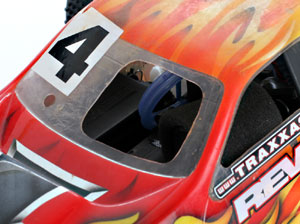
This
one should go without saying, but I can't stress enough how important
it is to provide a good amount of airflow to the cooling head of your
engine. Cut out about a 2-inch hole (round or square) into the
windshield on the same side that the engine is located. It doesn't hurt
to cut a little out of the drivers side window as well, to allow even
more cooling.
Tank cutout
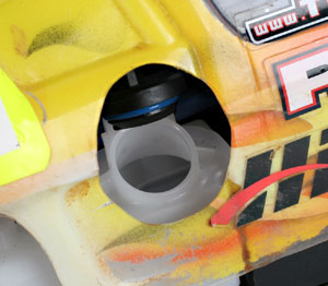
Making
the opening for the filler cap large and easy to use is the most
important part of this mod. A larger opening allows easier access,
which will speed up your pit times and cut down on the chances of a
mistake from your pitman. Make sure the hole is cut high enough to open
the tank lid fully, and so you'll be able to fuel accurately even at
extreme angles.
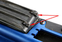
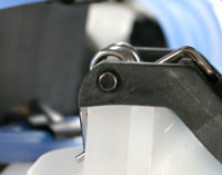
Roll bar trimming
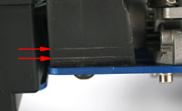
Many
Revo owners are unaware of what the two little lines are at the bottom
of the roll bar are for. These lines are actually there to show where
to cut when lowering the body. Each mark is an equal distance from one
another, just as each screw pin hole is on the body mounts.
This
means for each mark cut off of the bar, the body can be lowered one
hole to match. This keeps the top of the bar up against the inside of
the cab, where it needs to be. I generally run mine in the stock
position for extra protection against damaging the engine and exhaust
system, but the adjustment is there for those who want to lower CG, or
to just get that slammed look.
Cross-drill rear body mounts
Tired
of losing rear body clips? Cross-drill the body pin holes in the rear
body posts. This will allow you to insert the body clips into the posts
sideways, like the front end. This will help prevent the clips from
popping out during a crash or rollover.
Miscellaneous tricks
Trim the bumpers
| |
| Trim off the sidebars from the bumpers to "clean-up" the appearance and to make caster clips easier to access. |
Tank strap
Attach
an extra-long Zip-tie to the fuel cap on the tank for easier pitting.
The longer strap is much easier to grab quickly for fast pit stops.
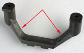
Fuel tank cap mod
Cut
off the material indicated by the red line in the photo. Remove
material from both sides of the cap to allow the cap to open further.
Be very careful not to cut into the tank.
Uncut Cut
Eliminate the On/Off switch
Switches are vulnerable to dirt and moisture. This can lead to failure from worn out contacts, or from shorting the circuit.
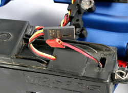
This
failure can't be detected beforehand, so you risk the chance of the
switch failing during a very important race. A failed switch could not
only end your main prematurely, but it can also cause a runaway, which
can be very damaging to your engine and chassis.
Using a servo
extention wire to directly connect the battery to the receiver will
eliminate that from being possible. Just plug-in when you're ready to
race.
Stayed tuned to Traxxas for more information..
Article ID: 472 |
|
| Last update: 2006-01-23 10:31 |