Building the Associated L4 Type Front End
Words: Mark Payne
(Mark
Payne's 1:12th Scale RC Notes)
Introduction
I use the Calandra CRC
Carpet Knife 3.2R but the following build note apply to any car using
the Associated reactive castor "L4" type front end.
I am heading towards
explaining how to fully tweak out the CRC Carpet Knife 3.2R chassis.
Before we look at the final tuning of the whole car it is important that
the Associated front end is built as consistently and accurately as
possible.
Get it right!
Fractional errors and
“left to right” differences in spring lengths, shimming, block
moldings and general alignment within the front end will cause
unpredictable handing on the track.
It took me a whole season of 1:12th racing to realize that the driving the car is hard enough on its
own without the thing wanting to pull right or left under acceleration.
I am not an “inch perfect” driver but I am learning to build and
inch perfect car. Unfortunately, predictability measured in inches on
the track needs accuracy down to fractions of a millimeter or 1/100th of
an inch .. or better!
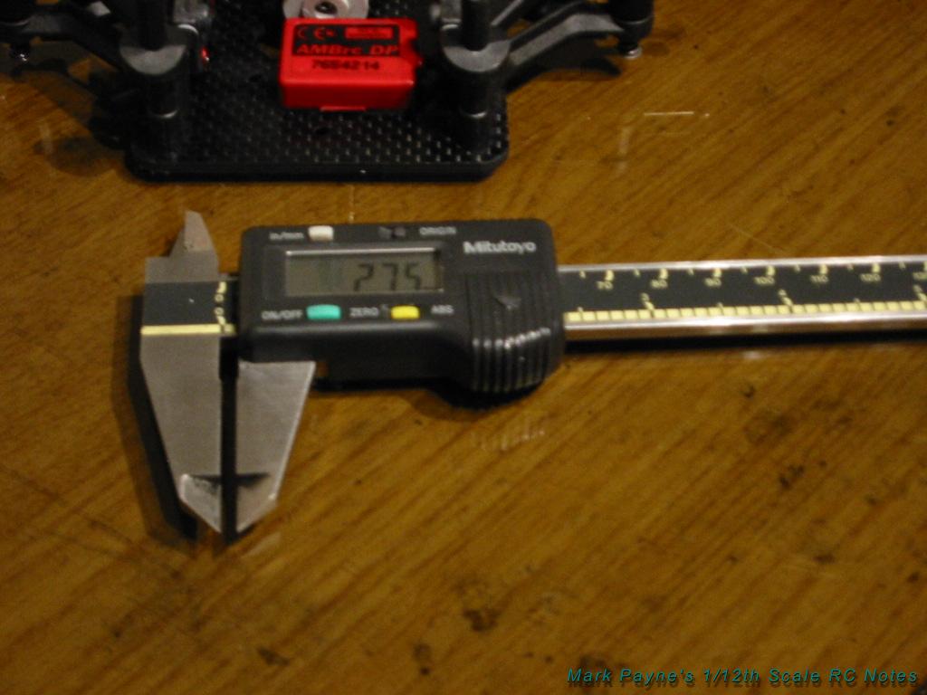
You are going to need a set
of Vernier calipers to make the required measurements. I use a digital
one from Mitutoyo
Step 1: Checking the
Lower Arms
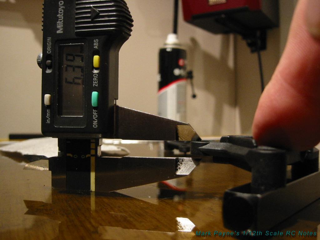
Using your flat surface (I
use a 2.5 sq ft safety glass offcut), make sure the Associated left and
right lower arms are the same height. You will be surprised how
different these things can be. I have had two arms from the same packet
as different as 1mm (0.04 in).

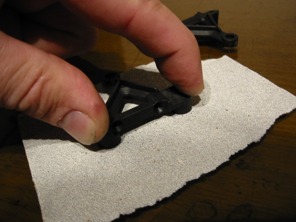
If there is a difference,
you will need to “grind” the high one down until they match. To do
this, lay a new flat piece of 200-300 grade abrasive paper on your flat
surface and apply an even pressure, keeping the molding parallel to the
surface. It is important that you do not grind an angle into the block
as you remove the material.

In measuring here, the
critical height is from the glass plane to the upper surface of the arm
where the ball gets inserted.
Step 2: Choose your
balls
I have found a much
better king pin pivot ball than the standard kit part.
The suspension balls I use are Teflon coated. You will end up with a
much freer suspension using these parts while keeping the suspension
free of play.
I think IRS do these also.
Not cheap but worth it… trust me.
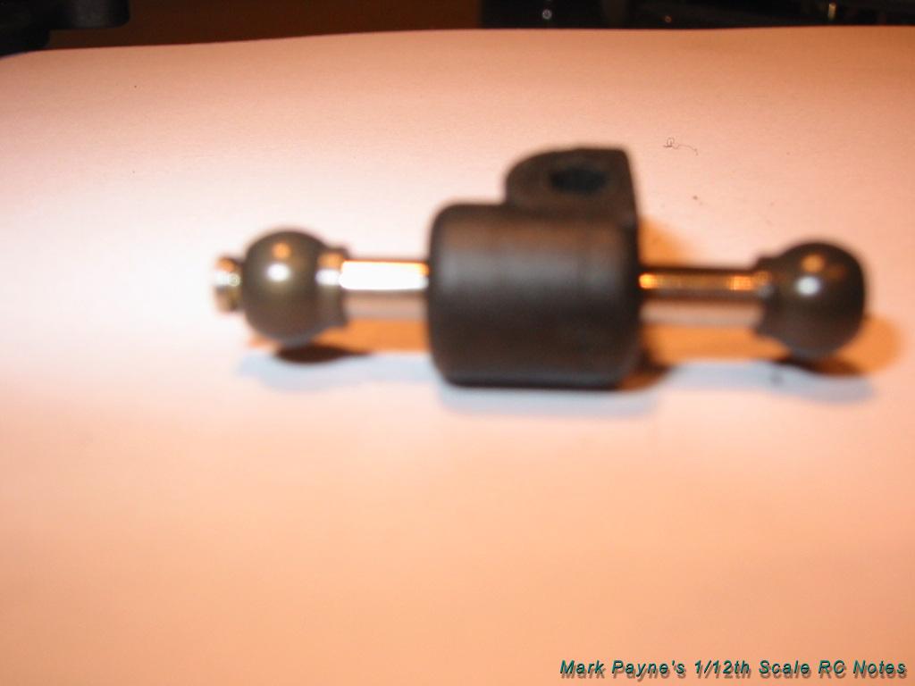
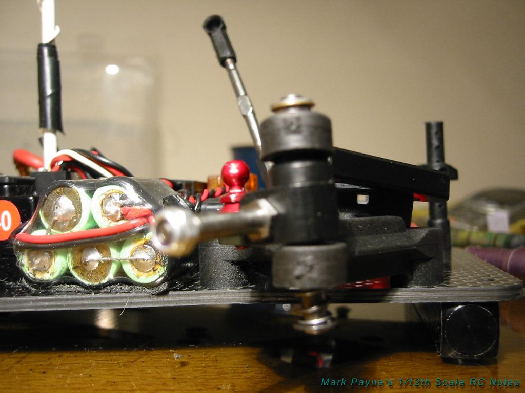
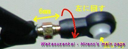
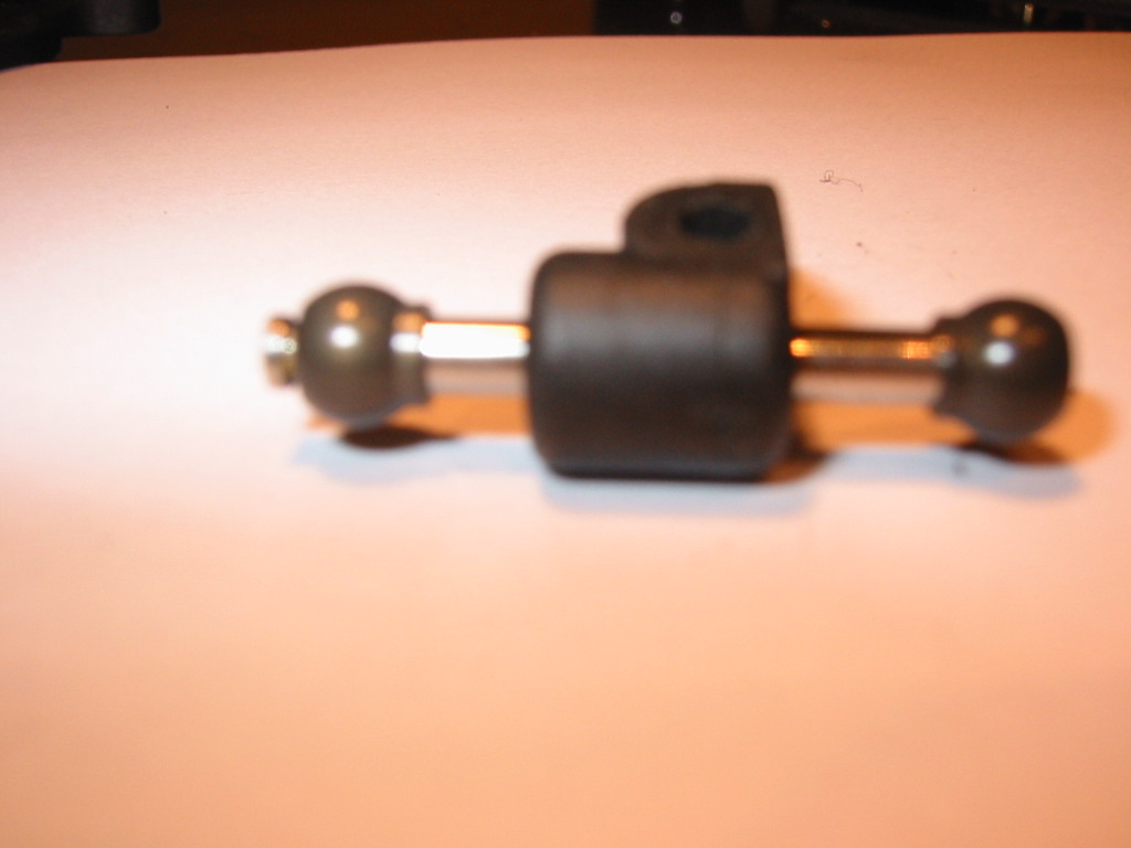
Finally, when you push the
balls into the moldings, make sure the collar is orientated towards the
steering block. The collar will be pointing up in the lower arm and down
in the top ball joint.
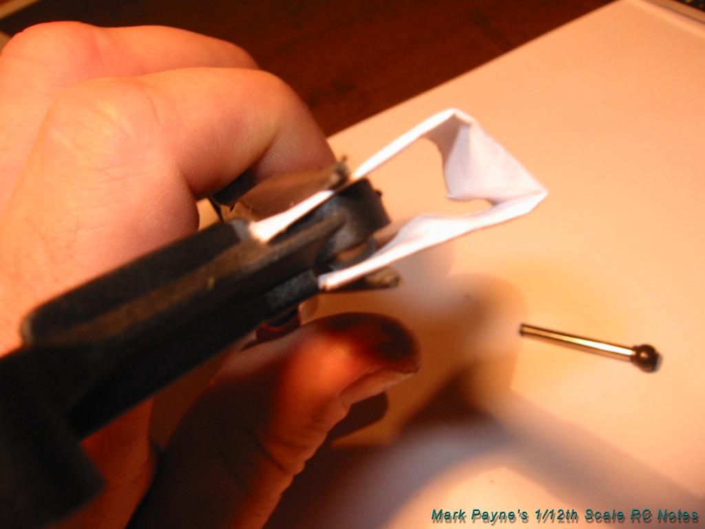
If you use pliers to force
the balls into location, do use some folded paper to prevent the pliers
from causing damage.
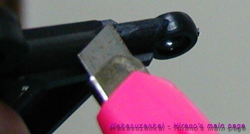
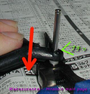
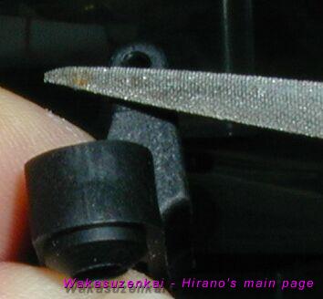
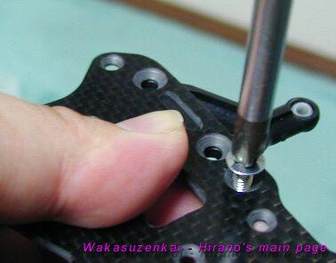
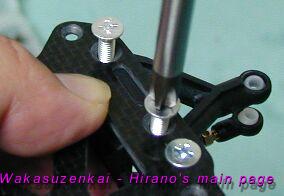
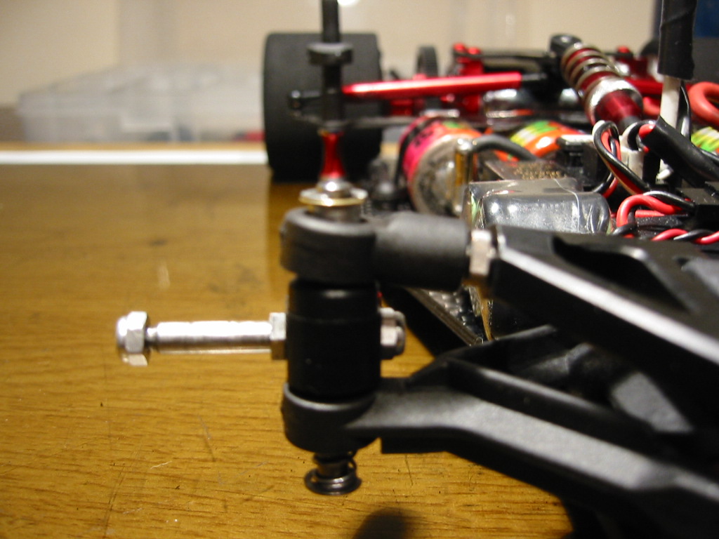
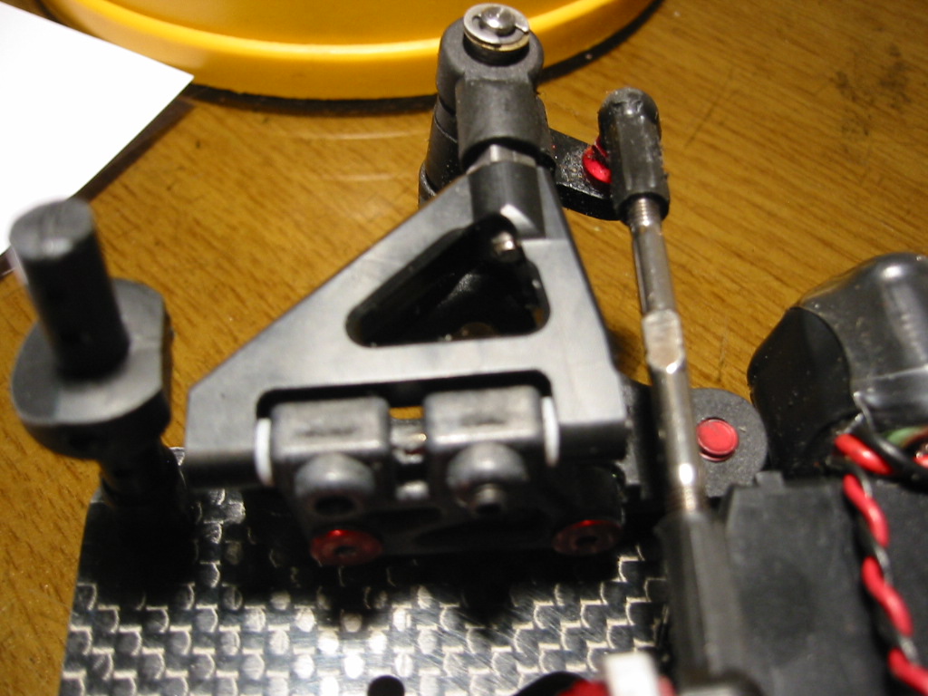
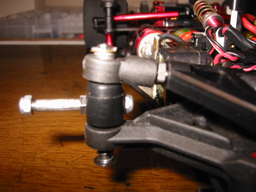
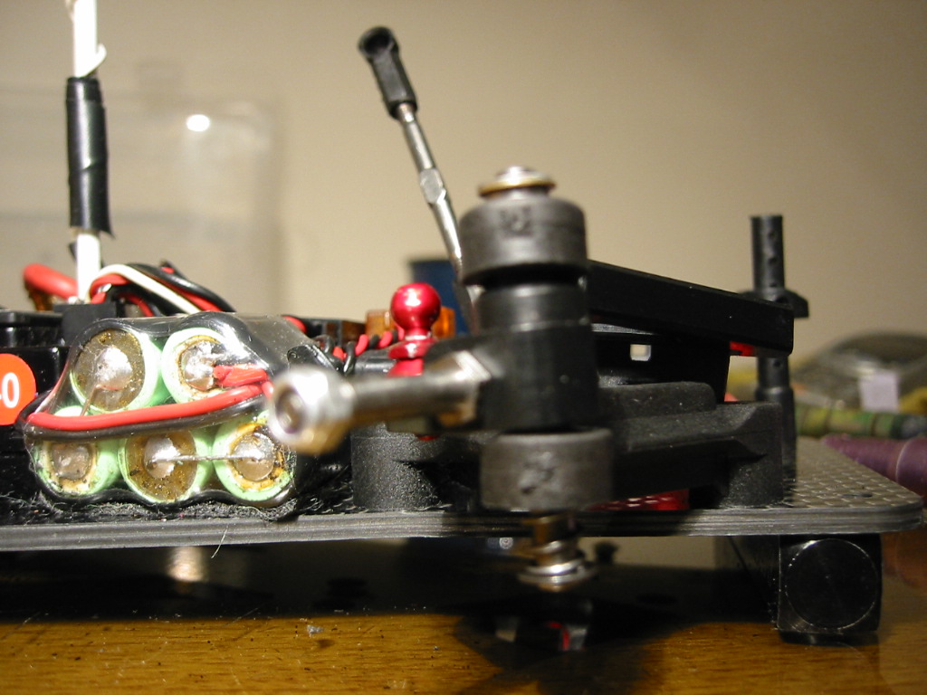
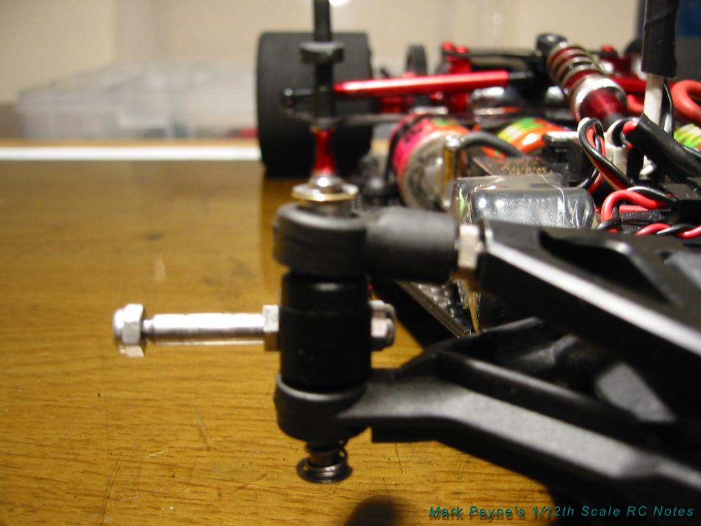
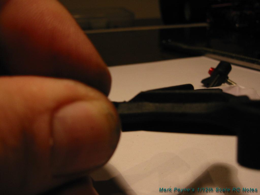
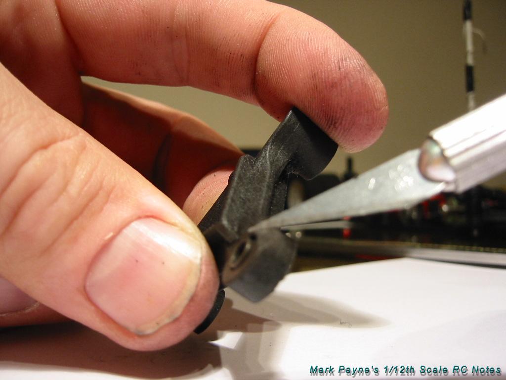
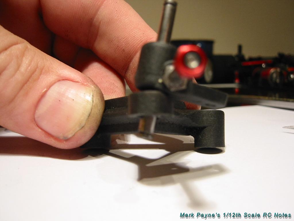
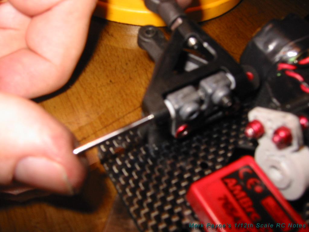
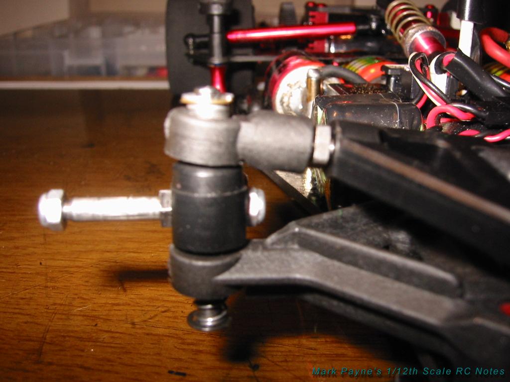
Step 3: Trim the
lower arms
If you use the CRC front
axles (as I am sure you do.. the titanium ones are great!) the securing
nut on the inside of the front block will hit the lower arm on full lock
so some trimming is needed here. The two photos below show this trim.
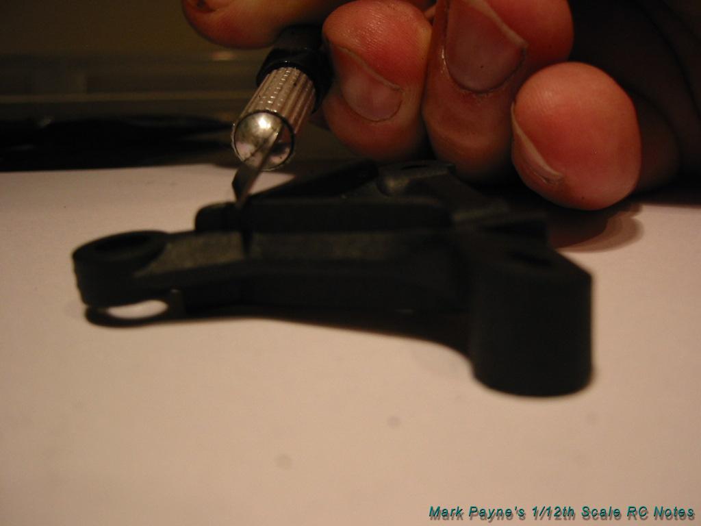
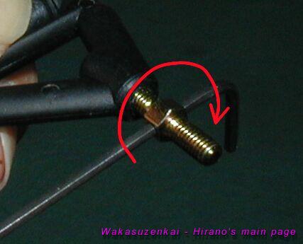
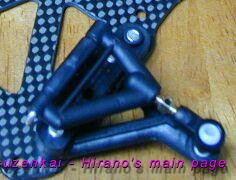
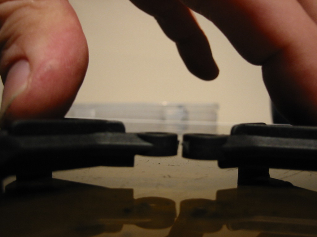
Also when the suspension is
built the steering block must ride top and bottom on the metal pivot
balls, not the lower arm or the upper ball joint plastic moldings.
The castor of the steering
block (as a result of the king pin angle) tends to make it bind on back
edge of the lower arm while steering, lifting it off the lower ball. To
stop this, trim some material off of the lower as shown.
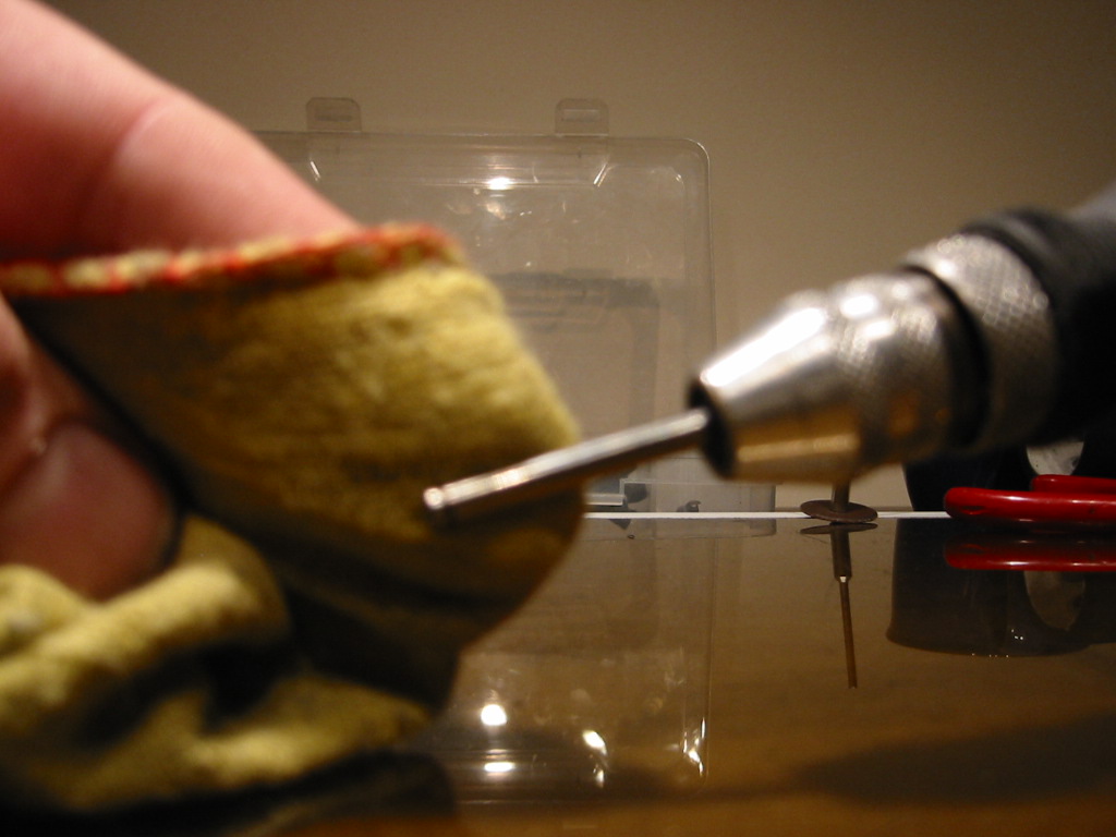
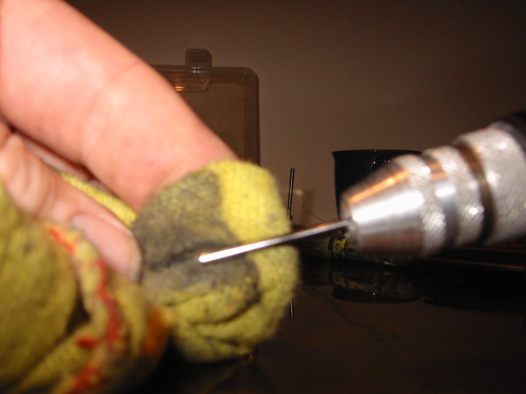
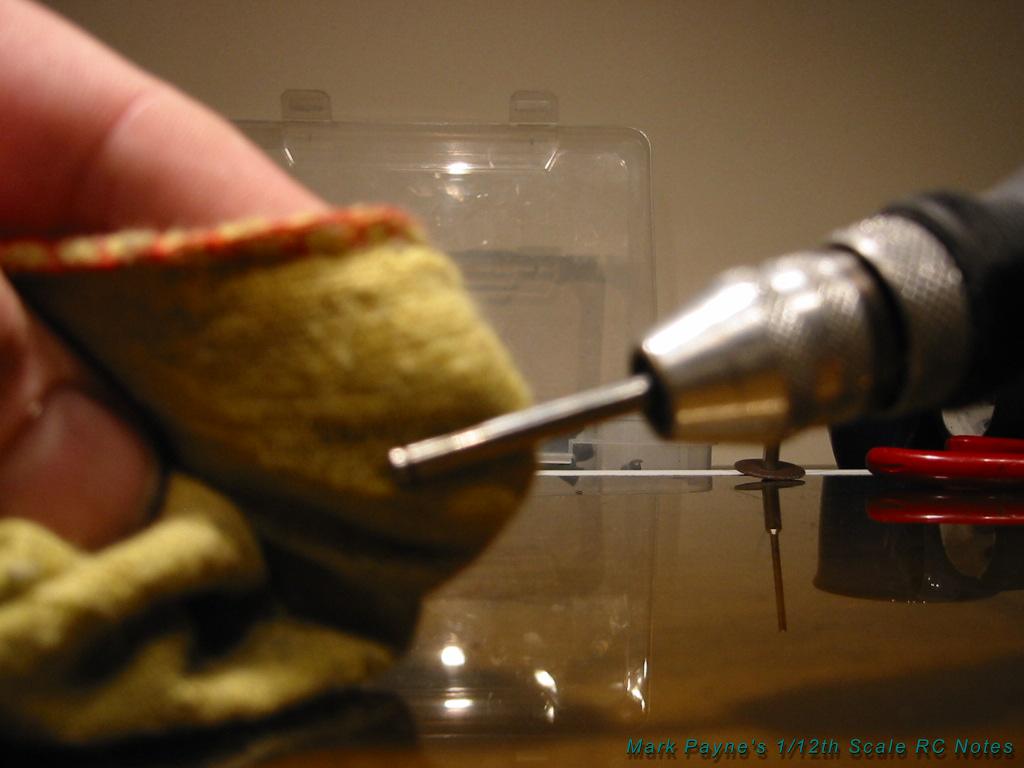
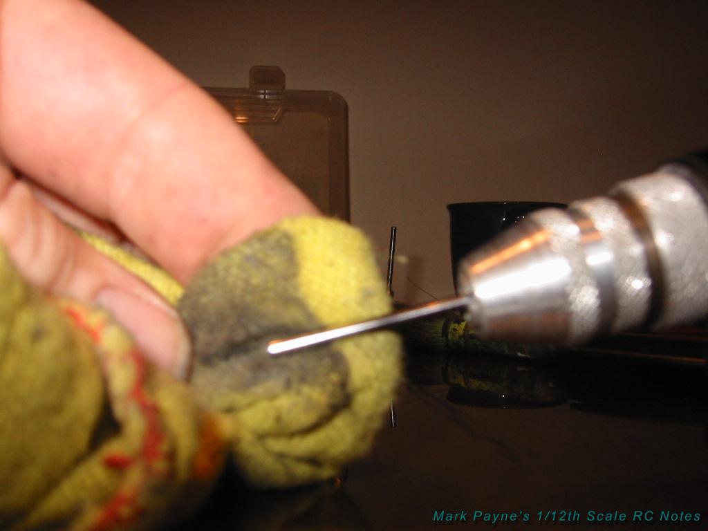
Step 4: Polish the
king pins
It’s a simple thing to do
but it makes a real difference to the feel of the suspension. Make sure
the king pins move freely in the pivot balls. I use a house hold metal
polish to do this. After polishing it is important that all residue is
removed. If you fail to do this the polish grit itself will become a
binding agent in your suspension.
The king pin may be burred
where the slot for the E clip has been machined. This makes the king pin
slightly oversized and it may scratch the ball as you push it through. A
light touch with abrasive paper around the ends followed by a polish
will solve this problem.
The king pin moves through
the lower arm ball like a piston as the suspension compresses on the
spring so it is important to make sure this area runs especially free.
It is also important for the
king pin to move freely through the steering block. I use the optional
Delrin CRC block. This is more accurate than the stock Associated
molding.
… the reaming for the king
pin is really nice and free… but…. There is a problem here. The
Delrin blocks include stock axles but if you screw in the CRC threaded
axles, the king pin hole tightens up and the suspension will bind.
After screwing in the CRC
axles it is necessary to ream out the king pin hole to an accurate 1/8th
fitting again. You can do this by hand using a 1/8th drill or (even
better) a 1/8th reamer. Alternatively, just stick with the stock axles
that come with the blocks.
Step 5: Polish the
upper pivot pins
I have started to use the CRC
optional Delrin upper arms as they are more accurate than the
standard associated ones.
The upper pivot pin can bind
on these arms, mainly because the tolerances in the pivot hole on the
CRC part is tighter.
Polish the pivot pins,
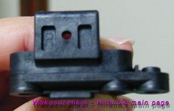
especially at the ends where the bearing surface is made with the upper
arms. You do not need to get the pin to run free in the reactive castor
angle block (the 0°, 5°, 10° part), you will probably want to lock
the pin in place with a grub screw here anyway to hold the pin fast.
When assembled, the top arm
should pivot around the pin with no noticeable friction, damping or
binding.
Handling note: I normally
run the 10° reactive castor block which does offer the most aggressive
steering out of the three (10, 5 and 0°). I will reduce to the 5°
block if the car is too snappy on the front.
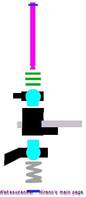
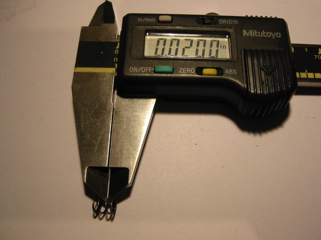
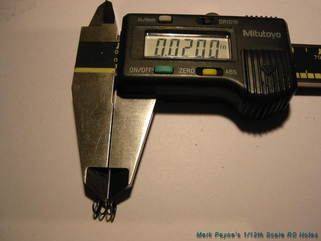
Step 6: Shim and
Spring the King Pins
Handling note: My starting
point is to work with the 0.020 in. front spring. The spring number is
referring to the diameter of the wire used to form the coil. The higher
the number, the thicker the wire and stiffer the spring. Optional
springs are as follows:
-
0.018 in. Soft
-
0.020 in. Medium
-
0.022 in. Hard
-
0.024 in. very Hard
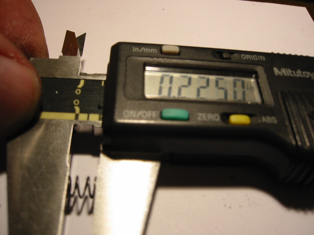
Spring Errors
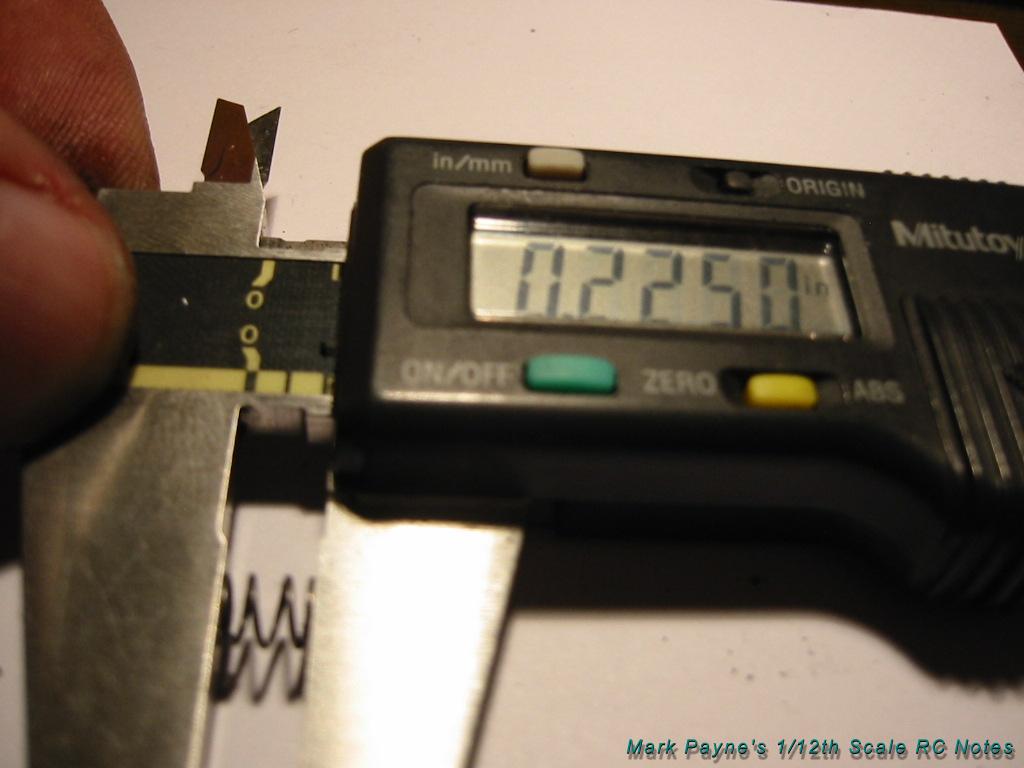
First pick two springs with
the same thickness and measure them with your calipers to double check
yourself. I know this sounds stupid but I have made mistakes in the past
and ended up running different springs left and right!
It is also important that
both the springs are the same length to within 0.01 in (0.25 mm) which
is the thickness around two shims. If the springs differ by more than
this I would assume that one has collapsed and is damaged. Get a new
pair.
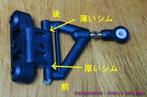
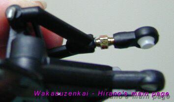
Adding Shims
I like to shim the king pins
so the play is just taken out of the assembly when there is no load on
the suspension. The shims are applied to the top of the king pin between
the top ball and the upper E-clip. Do not use motor shims as their
outside diameter is too large and they will bind up in top ball joint
molding.
The correct shims for this job have an outside diameter of 4.92mm
(0.1940 in).
The two shims sizes I have
are 0.11 mm (0.0045 in) and double that at 0.22 mm (0.0090 in).
If you use the Teflon coated
balls (as mentioned above) with the 0.020 spring and have trimmed the
back part of the lower arm also, a good starting point for the shim
stack is 2.22mm (0.0870 in). The problem with giving this measurement is
that there are so many variables including the balls, steering arm, king
pin length and even the E clip thickness.
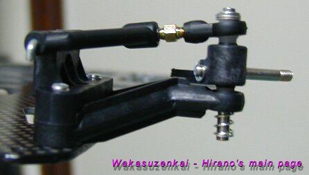
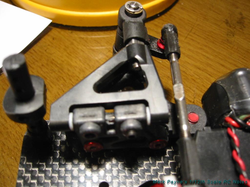
Step 7: Final Check
Finally mount the front end
on the car.
Adjust the servo links for 0°s
toe. Then use a camber gauge to get to set 1° of negative camber.
Always remember, when using
the turnbuckles to adjust the front camber, ensure the top ball joint
part finishes inline with the king pin. That will mean that it is angled
back slightly.
Finally check that the shims
have just taken out all of the king pin play and that the suspension has
the same free feel when you compare left to right.