|
- X-6 CUBED ASSEMBLY INSTRUCTIONS -
Previous - Table of Content - Next
BAG F - FINISH IT UP
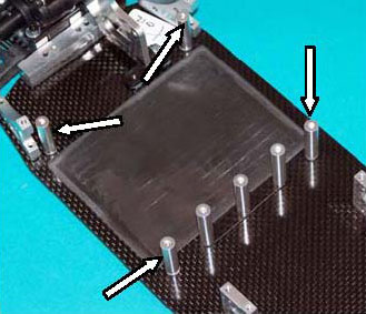
F1) Place two 3/8" flat head screws up through the two holes at the right rear corner of the chassis.
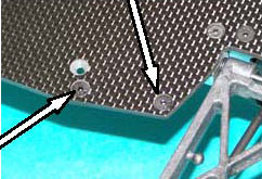
F2) Remove the bag of Chassis Shims (XF 1012) from Bag F and place one of the medium-size shims over the two bolts from F1 above. Then bolt on a Rear Top Deck Support (XF 1311). If you use thread lock, a drop in each hole of the top deck support. Repeat for the left side.
F3) Place three 4-40 X 3/8" flat heads up from under the chassis in the center just ahead of the battery compartment and put the long chassis shim over them.
 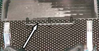
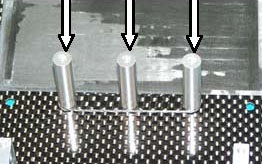
F4) Install the three long 1" Stand-Offs (XF 6801). A drop of thread lock on the standoffs if you use it. Again, a cloth and some pliers will help.
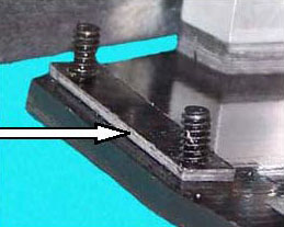
F5) Place four 4-40 X 3/8” flat head screws up through the chassis, one at each corner of the battery compartment, and put a 0.060” shim on each bolt.
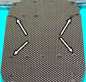 
F6) Install the four 7/8” Stand-Offs (XF6802). If you are into thread lock, a drop in each one.
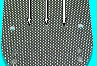
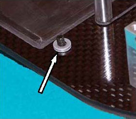
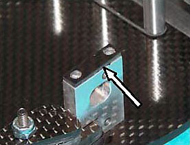
F7) Find the two button head screws you saved from inst. 11 and the two 4-40 X 1/4 button head screws (XF 6041) from Bag F. Install the four 0.156" Hex Stand-Offs (XF 6805) in the slots of the battery strap (XF 1229). Finger tight for now. The stand-offs will hang down to locate the battery.
F8) Check the Set-Up Sheet and Tuning Section, then put the battery in the car where you want it. Now put the battery strap in position, hold the strap in with four 4-40 X 3/8" button head screws (XF 6042) finger tight, and adjust the stand-offs to keep the battery in the desired position. Now tighten the stand-offs. You can leave the battery in for now or remove it, then tighten the battery strap to the 7/8" stand offs. The side of the battery strap with the dog leg is the front.
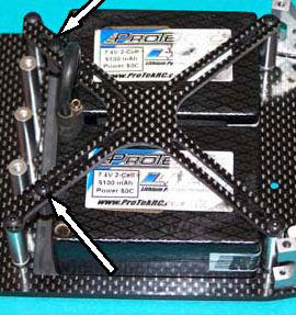
F9) SADDLE PACK - Use the battery spacer foam (AE 9238) from your B4.2 between the two saddle batteries to space them out to the edge of the battery compartment. For pack forward (left photo) use only the rear two hex stand-offs, adjusting them to hold the battery tight against the front of the battery compartment. For pack back (right photo), use the front two hexes.
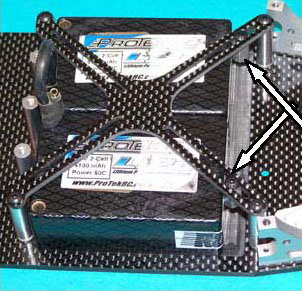 
SHORTY PACK Here you have more choice of placement. The pack can go anywhere in the battery compartment.
Pack Forward
Only 2 rear hexes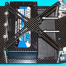
|
Pack Center
All four hexes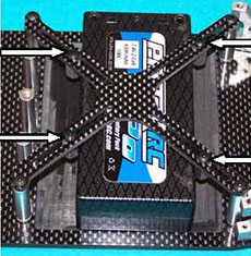
|
Pack Back
Only 2 front hexes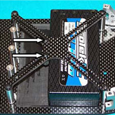
|
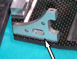
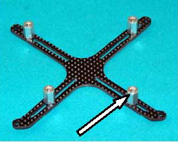
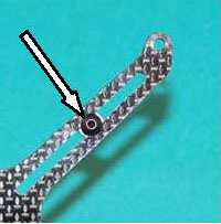
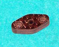
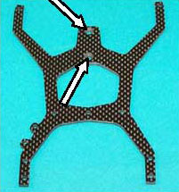
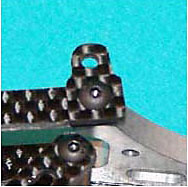
F10) Put the Antenna Mount (left photo, XF 9001) on the bottom of the Top Deck (XF 1503). The bottom of the top deck is the side with the two countersunk holes (center photo) which accept the bracket of the optional Transmission Brace (not included). Use the two 4-40 X 1/2" button head
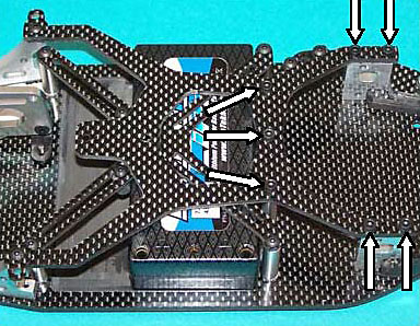
F11) We are showing you the top deck here because it makes sense to us this way, but you may want to install the electronics before the top deck. Place the smallest two chassis shims on the front top deck supports (left photo) and place the top deck over its supports. Use seven 4-40 X 3/8" cap head screws for the front deck supports and center posts.
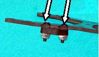
 F12) Place a 4-40 X 3/8" Button Head screw through each dialed carbon fiber (!) Body Mount (XF 6321), then attach the rear of the top deck. The body mounts should be at 90° to the top deck, not the top deck support. Team drivers often put a small bevel around the top and bottom of the rounded portion of these body mounts so the body clips slide on and off easier. F12) Place a 4-40 X 3/8" Button Head screw through each dialed carbon fiber (!) Body Mount (XF 6321), then attach the rear of the top deck. The body mounts should be at 90° to the top deck, not the top deck support. Team drivers often put a small bevel around the top and bottom of the rounded portion of these body mounts so the body clips slide on and off easier.
ELECTRONICS
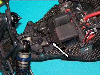
F13) Mount the servo in the Cubed just as it was in the B4.2. Attach the servo link. If you have not removed the servo horn, if should be set perfectly. Don't be confused. This is a photo of Paul's car and he mounts his transponder and E.S.C. capacitor on top of the servo
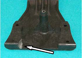
F14) If your servo is wide, it may foul the corners of the nose piece. Not to worry, just use a file or a rotary tool to remove about 1/8" of material from raised corner of the nose piece where indicated. We have been doing this for several years and there is lots of material here, so you won't weaken it. Only the left side has been done in this photo so you can see the difference.
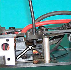
F15) Install the antenna tube into its mount by pushing it through from the top. Extend a part of the tube down below the mount so the wire does not touch the CF. This helps keep the glitch demon in his cage.
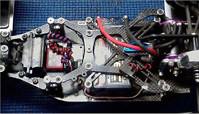
F16) The photo on the left is Paul's car with E.S.C. and receiver installed. The right photo is Team driver Dan Reino's car with the shorty pack forward and the E.S.C. between the battery and motor. Dan's way is not legal for R.O.A.R. but it works well at Thunder R/C, Dan's home track. Of course, you can do this any way you want!
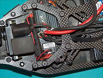 
You can get some more inspiration by checking others electronics setups.
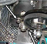
F17) Install the motor, using the saved screws.
Previous - Table of Content - Next
|
