|
- X-6 CUBED ASSEMBLY INSTRUCTIONS -
Previous - Table of Content - Next
BAG A - TRANSMISSION BALL DIFFERENTIAL
The B4.2 and B4.1 diff uses metric outdrives and the X Factory 4-Gear transmission uses U.S. measurement, so we'll re-build the whole thing now. If your donor truck is a B4, you have the U.S. sized outdrives & bearings. They fit the 4-Gear.
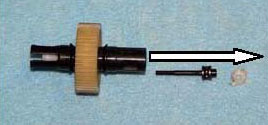
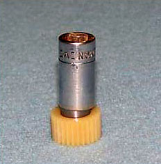
A1) Hold the outdrive with the T-nut (AE6575) in one hand and insert the Allen driver through the white protector cap (AE6575) and into the head of the diff thrust bolt (AE6573). Unscrew the bolt. Use the T-nut to push the bolt through the diff and out. The white cap will come with it; set it aside for reuse. Make sure the thrust bearing stays on the diff bolt-and don't lose any of the six little balls! Take the thrust balls (AE6574) and washers (AE6573) off the bolt. Clean the balls, washers, and bolt, and set them all aside with the cap
 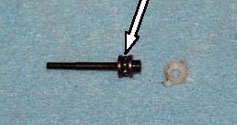
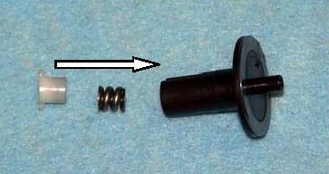
A2) Take the rest of the diff apart. Be sure to remove the T-nut and spring (AE6582) from the male outdrive. One diff bearing (XF 6204) should stay in the diff gear. The other may fall out or it may stay in the female outdrive.
A3) Remove the 12 diff balls (XF6500) and bearing from the gear (AE7664). Clean the balls and gear and set them aside to air dry. Clean and re-lube the two diff bearings, using just a drop of good bearing oil. Set the spring and T-nut aside with the gear, balls, and bearings. This leaves the outdrives in front of you. Remove the diff rings and clean them. Our second diff bearing wanted to stay in the outdrive, so we removed it now. The rings will be used in step A4 below. Metric outdrives can be discarded.
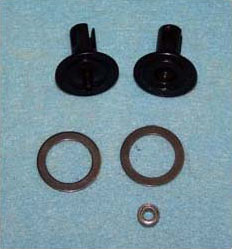
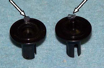
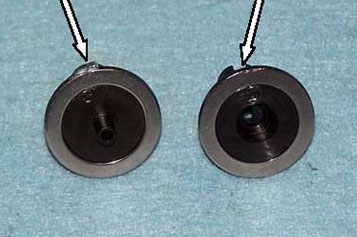
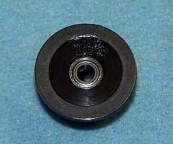
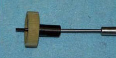
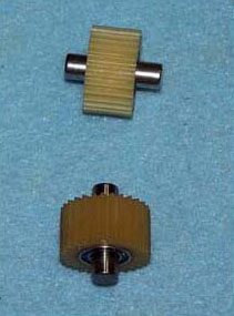
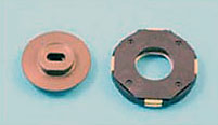
A4) Check your diff rings for wear. If they're not new, there will be a thin line on the face of each one where the balls run. Darker line = more wear. You can use both sides of the rings, so if one side has not been used, flip them over. Carbide diff balls like X Factory's #6500 are much harder than the rings, so one set of balls should last through several sets of rings. Many X Factory drivers prefer B Fast diff rings for smoother, longer-lasting diffs. Take the new outdrives (AE7667 & 7668) from Bag A and on each one put a small drop of diff lube on one part of the edge where the ring will go (left photo). This grease does not lubricate, it merely holds the ring on during assembly. Grease attracts dirt (bad) so use as little as possible here. Wipe off any excess grease (right photo).
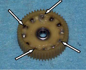
A5) Re-install the diff balls and one diff bearing into the diff gear. Put a small amount of diff lube on one side of each of the balls. We used too much in the photo so you can see the lube. You need surprisingly little lube, and excess is just thrown off inside the transmission case. Many X Factory Team drivers use B-Fast Pro Lube.
A6) Install the second diff bearing into the female outdrive.
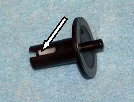
A7) Install the spring and T-nut into the male outdrive. Be certain the lugs on the T-nut engage properly in the slots of the outdrive. Set aside until A10.
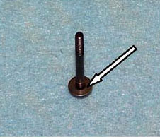
A8) Check the thrust washers for wear. They wear just as the diff rings do, and are also reversible. Stand the diff bolt up on end and install one washer on it with a new side up (left photo). Put some thrust grease all around the exposed surface of the washer and place the six thrust balls on the washer (center photo). We use a magnetized screw driver to pick up and place the balls. Then slide the other washer over the bolt, good side down (right photo). Don't use too much grease here-the assembly must be well lubricated BUT excess grease cannot escape and can cause the diff to malfunction! So after the inner washer is installed run your finger
A9) Put the thrust bolt, with thrust bearing, on your Allen driver, and install the bolt into the female outdrive (center photo). Leave the driver engaged in the bolt through step A 10. Now put the diff gear, with balls and bearing, over the bolt so the diff balls contact the diff ring (right photo).
A10) Now slide the male outdrive from step A7 into the female outdrive assembly from step A9. Slide the diff bolt through the male outdrive and screw it into the T-nut. Do not tighten very much yet. See A11 below.
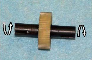
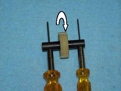
 A11) As the bolt begins to tighten, stop every revolution or two, remove the wrench, and rotate the two outdrives at the same time in opposite directions while pushing them together (photo on the right). This helps seat the balls, rings, and thrust bearing while it distributes the grease. Keep tightening and rotating until there is a bit of tension on the bolt. Now put an Allen wrench through the slots of each outdrive, hold the wrenches still, and rotate the diff gear, Continue tightening the diff bolt, twisting the outdrives and checking with the wrenches, until the gear will no longer rotate at all between the outdrives. (right photo). As soon as the gear is driving the outdrives, stop right there. Be sure the outdrives will still rotate against each other. This will be a starting point for diff break-in and final adjustment. A11) As the bolt begins to tighten, stop every revolution or two, remove the wrench, and rotate the two outdrives at the same time in opposite directions while pushing them together (photo on the right). This helps seat the balls, rings, and thrust bearing while it distributes the grease. Keep tightening and rotating until there is a bit of tension on the bolt. Now put an Allen wrench through the slots of each outdrive, hold the wrenches still, and rotate the diff gear, Continue tightening the diff bolt, twisting the outdrives and checking with the wrenches, until the gear will no longer rotate at all between the outdrives. (right photo). As soon as the gear is driving the outdrives, stop right there. Be sure the outdrives will still rotate against each other. This will be a starting point for diff break-in and final adjustment.
CLEAN & INSPECT
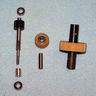
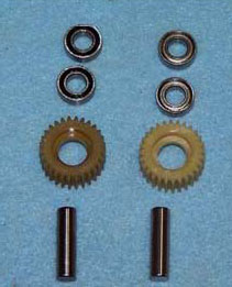
A12) We suggest you clean and inspect the rest of the B 4.2 transmission parts at this time. If you re-lube the bearings, make sure the outside is clean and dry so they do not attract dirt. You need the following items from your B 4.2: the assembled diff, the idler gear (AE9360) with its shaft (AE9361) & two 3/16" X 3/8" bearings (XF6202), and the top shaft (AE9601) with its spacer (AE9602) & two 3/16 X 3/8 bearings (XF6200). Replace worn parts as necessary.
ASSEMBLE THE X-6 Cubed TRANSMISSION
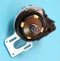
A13) Remove the transmission case (XF5001) from Bag A and separate the two halves. Note the small round ejector pin bosses on the mounting tabs. You may wish to file these flat for ease of installation in the truck.
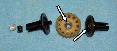
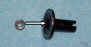
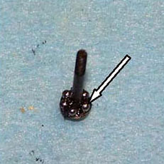
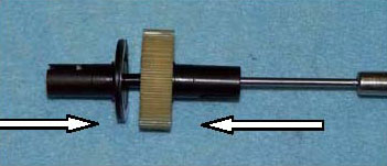
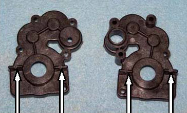
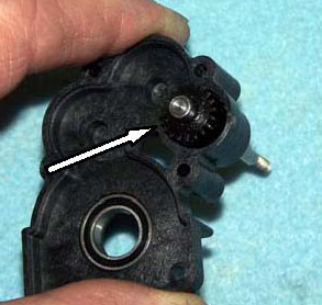
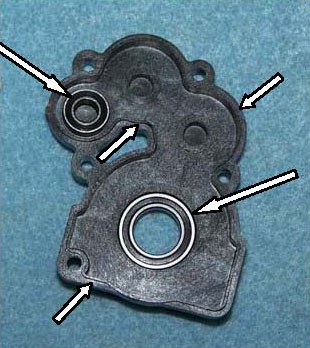
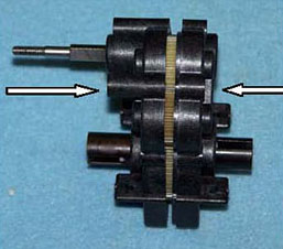
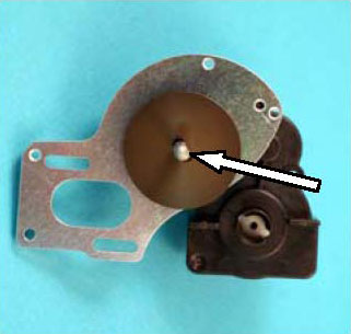
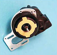
A14) Install a saved 3/16" X 3/8" rubber sealed bearing (XF6200) all the way into the top shaft boss in the left transmission case half (short arrow) and a 3/8" X 5/8" (XF6203) bearing from Bag A in the boss for the differential (long arrow). The Team pushes them in with the shank of an Allen driver or, better yet, with a socket. See Inst. A16.
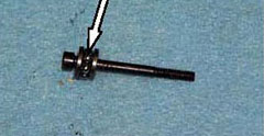
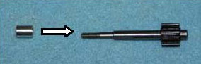 A15) Make sure the spacer (AE9602) is on the top shaft (AE9601) and slide the shaft with spacer through the bearing in the transmission case. If your top shaft is worn, you will want to try our one-piece steel top shaft (XF5210) made for us by M.I.P. No more spacer to lose and longer wearing too! A15) Make sure the spacer (AE9602) is on the top shaft (AE9601) and slide the shaft with spacer through the bearing in the transmission case. If your top shaft is worn, you will want to try our one-piece steel top shaft (XF5210) made for us by M.I.P. No more spacer to lose and longer wearing too!
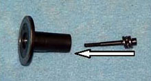
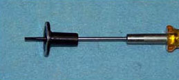
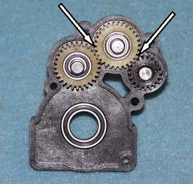
A16) Gather together the idler gear from the B 4.2 (AE9360) along with its 3/16" X 3/8" bearings (XF6202) and shaft (XF5201) along with the same parts from bag A so you have two gears, two shafts, and four bearings. Install a bearing into each side of both idler gears. Team drivers do it by pushing on the outer race with a socket.
A17) Slide an idler shaft through the bearings in each idler gear, then place the shafts in their bosses in the left transmission half. Be certain all gears mesh properly and the transmission turns smooth and free. Transmission should be free and smooth.
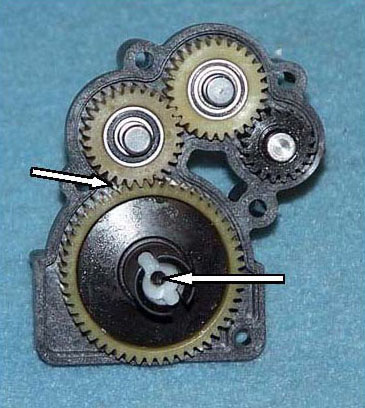
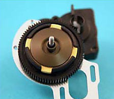
A18) Install the diff in the left transmission case bearing, ensuring it meshes properly with the idler gear. The head of the diff bolt should be up. Again, the transmission should be free and smooth.
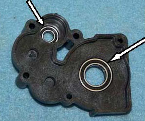
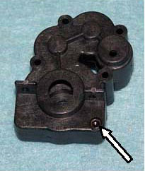
A19) Install the remaining 3/16" X 3/8" rubber seal bearing and 3/8" X 5/8" bearing into their bosses in the right transmission case half. (long arrows) There is a small hole in the case where the top shaft bearing goes so you can use a hex wrench to push out the bearing. Some drivers like to run a small bead of inexpensive grease around the mating surface of the right transmission case half. (short arrows) This grease is to seal out dirt, not to lubricate anything, so be thorough but don't over-do it. Other Team drivers have discovered that the X Factory 4-Gear transmission case seals so tightly that they do not use the grease. It's your choice.
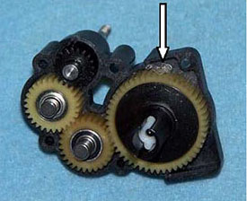
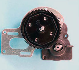
A20) Some Team drivers put a small glob of grease on the diff gear to lubricate the transmission. That little glob will be spread throughout all the gears as the trans turns, so one little one is all that's needed. Other Team drivers use no grease, saying the trans is freer that way. Pay your money and take your pick. Carefully put the two halves of the transmission together, sliding the outdrive through its bearing, the two idler shafts into their bosses, and the top shaft into its bearing. Make sure everything rotates very free and smooth. No hitches, no slow-downs. Now is the best time to fix any problem. Wipe any excess grease from the outside of the case.
A21) Install the 4-40 X 3/8" cap head bolt (XF6001) in the lower corner of the trans case, just finger tight for now to hold things together.
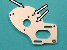
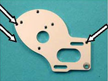
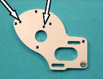
A22) The X Factory 4-Gear motor plate (XF1234) has four "extra" holes. Two of them (left photo, short arrows) are used to install the optional #5050 heatsink and fan. Two more may be used later if we make a gear cover (center photo, short arrows). Long arrows in the right photo point to the three holes that attach the motor plate to the transmission. Team drivers put a drop of threadlock now in these three holes. Don't put the
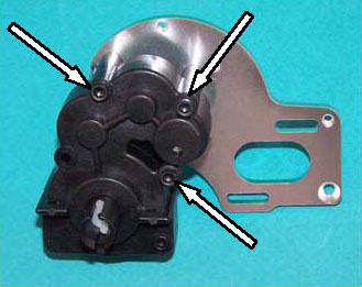
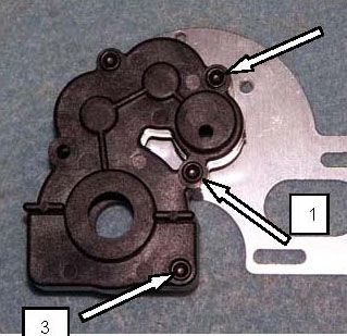
A23) Insert the three 4-40 X 1" screws from inst.16 through the three holes that go into the motor plate and attach the motor plate (left photo arrows). The center rear hole will not be used on the X-6 Cubed due to a clearance issue. Use a crossing pattern to tighten all four trans bolts to equal tightness. Check one last time that the transmission rotates free and smooth. This is your last chance!
SLIPPER INSTALLATION
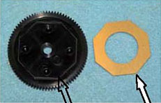
A24) Install a slipper plate (XF5530) onto the top shaft, flat side out. The flats inside the plate will key to the flats on the shaft.
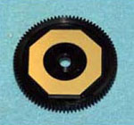
A25) Put the inner slipper pad (AE9603) on the spur gear (AE9651) (left & center photos). The hex of the pad fits into the molded hex in the gear. Now turn the transmission so the top shaft with slipper plate is facing down. Hold the plate on with your thumb and slide the spur gear, pad side up, onto the shaft so the pad & gear are tight against the plate. Keep pressure on the spur so the pad stays in its hex until step A27 below. This transmission is in the car!
A26) Turn the transmission back over so the top shaft is pointing up, but be certain the slipper pad remains engaged in the spur and the spur is tight against the plate. Now place the slipper housing, with pads and center plate, onto the top shaft, followed by the outer slipper plate.
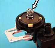
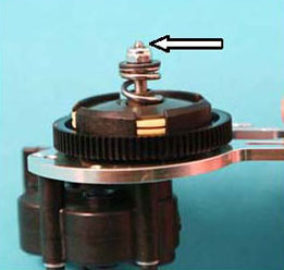
A27) Install the spring (AE9739) on the shaft so it fits into the slipper plate's hub, then place the black retainer (AE7486) over the spring, flat side up. Install the 5-40 nut (XF6074) to hold it all together, tightening until there is one thread of the shaft showing. Final adjustment later.
That's it for the hardest, longest bag. All downhill from here!
Set the trans aside and we'll do the front end.
Previous - Table of Content - Next
|
