Welcome to the 1st official article of the new Race Vehicles Series, featuring the TLR 22-4 2.0 4wd 1/10 scale racing buggy.
The TLR 22-4 2.0 buggy comes in kit version, so it needs to be assembled. I think assembling kits is one of the best parts about owning them! The kit is an all inclusive chassis, so we’ll still need to get all the electronics, tires, tire glue, and polycarbonate paint.
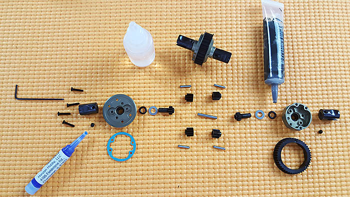
So let’s look at what’s included with the TLR 22-4 2.0 buggy.
Complete chassis (assembly required)
Polycarbonate cab forward body and rear wing (pre-cut, needs painting)
Plastic spacers (roll center (camber link height) and wheel base)
Aluminum spacers (roll center)
Rear sway bar (rear stability)
Shorty or Saddle packs configuration. (batteries not included)
Other tuning options in the kit (camber, toe, ride height, roll center, wheel base, center of gravity, shock position and angle, wing angle)
Many other tuning parameters can be achieved through purchasing parts or modification (rear toe, front caster, rear roll center through the pivot blocks, spindle height, shock dampening, spring rate, and many aluminum parts)
What’s needed: (see the 22-4 Electronics article (coming soon) for what I’ve chosen to use)
Brushless ESC (preferably sensored)
Brushless Motor (preferably sensored)
Steering Servo
Transmitter and Receiver (2.4GHz, 2-Channel)
LIPO battery pack (2S Shorty pack or Saddle Packs)
I’m not putting this next item on the list, since it’s not NEEDED to complete the kit, but stocking up on some spare parts is always a good idea. I’ve found that trying to be fast, while learning a new kit, makes it easy to hit things. Lol
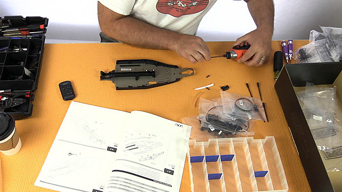
The Build
Steps A1 – A3
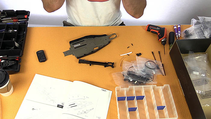
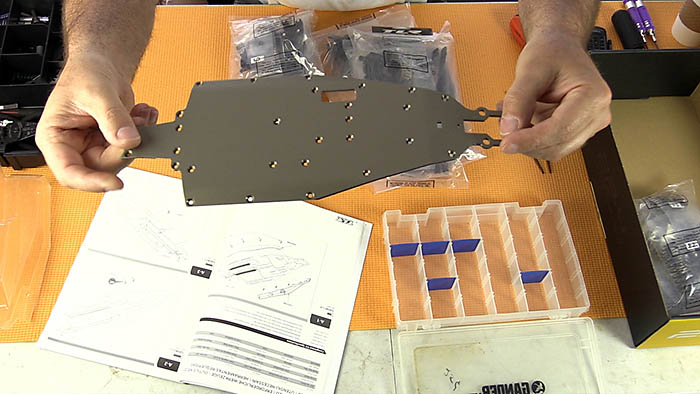
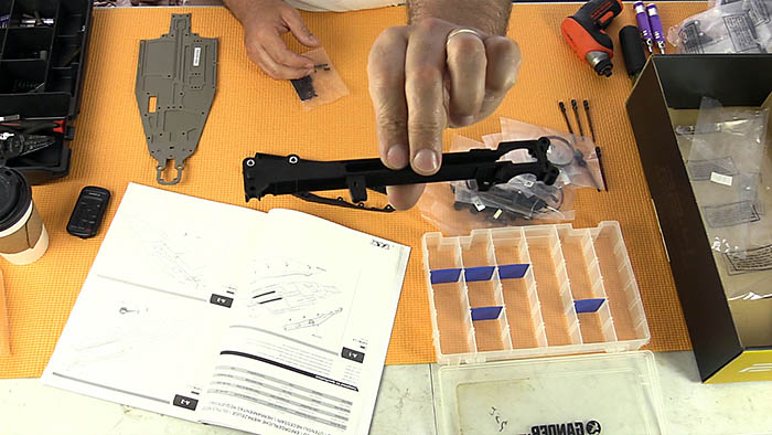
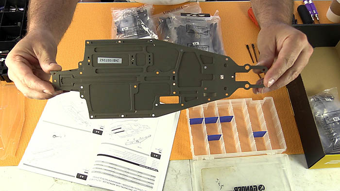
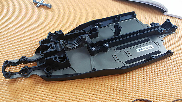
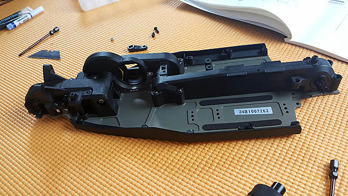
The CNC machined 2.5mm chassis has milled pockets for reducing weight and is coated in a semi-rough finish. A mudguard attaches to each side of the chassis with countersunk hex screws. The rear sub-frame/lower belt channel has aluminum threaded inserts molded into the plastic.
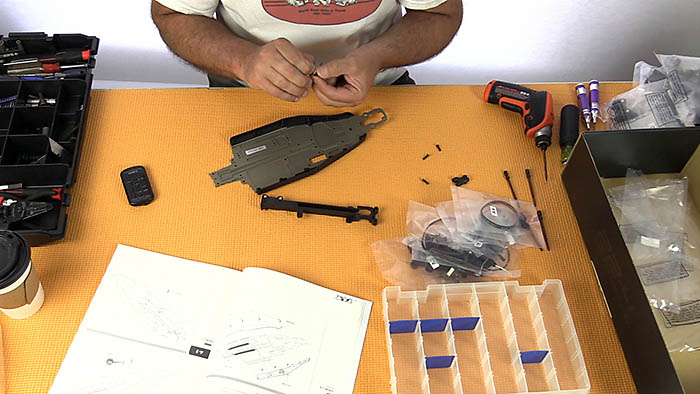
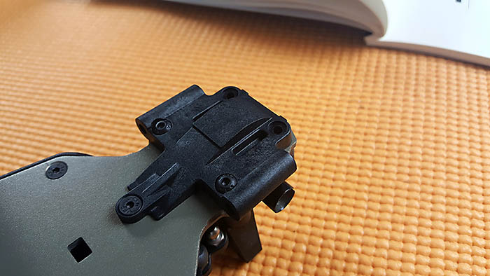
Steps A4 – A7 The machined aluminum motor mount snaps in-between two plastic lower belt covers, which are also part of the subframe. After snapping the three pieces together, the unit gets screwed to the front of the chassis. This is where the front differential, slipper unit, motor, and one side of the jack shaft will sit.
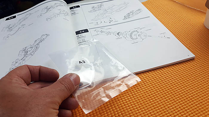
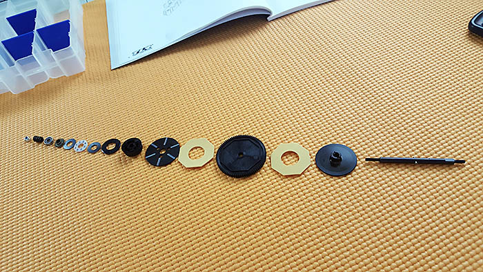
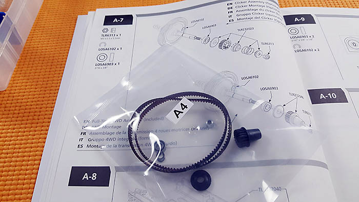
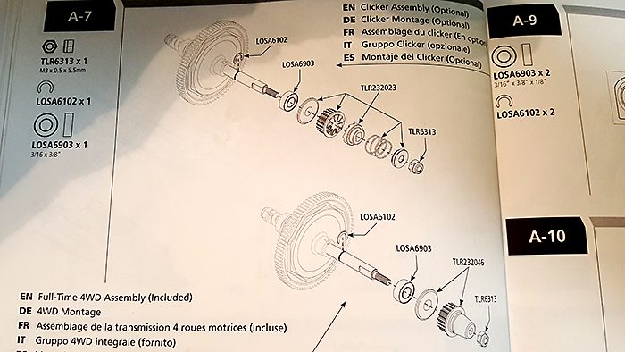
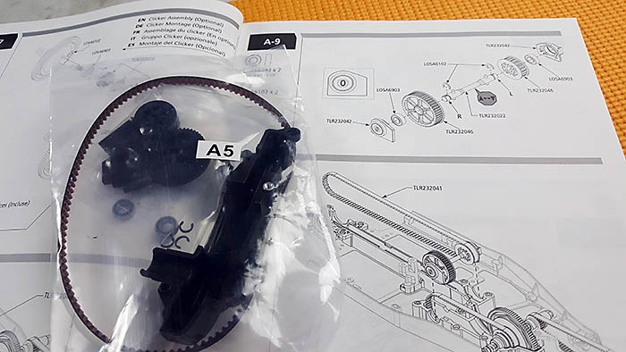
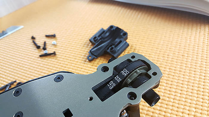
Step A6 requires assembling the slipper clutch unit. When looking for the parts bag, I noticed it was labelled incorrectly. The slipper assembly was in bag A3. As you can see in the images, parts bag A4 actually contained the parts for step A7. This actually happens a few other times throughout the build. It’s not a big deal, since the bags are clear and you can easily see the parts inside, but…………..
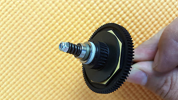
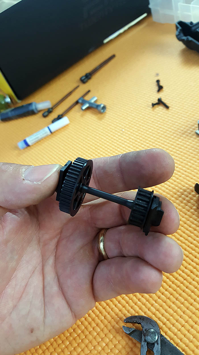
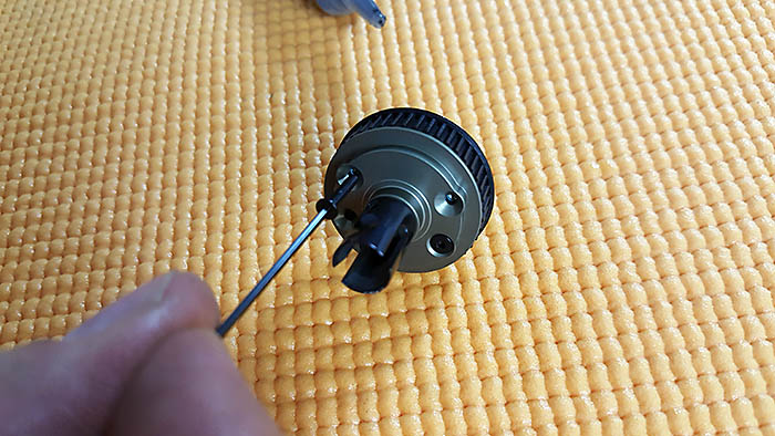
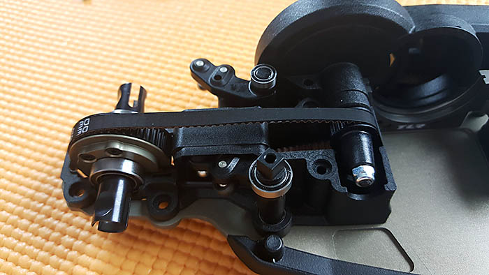
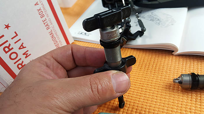
The slipper clutch uses two slipper pads, one on each side of the spur gear. Near the thrust bearing is the tension spring, and a good starting point is with the end of the slipper nut flush with the end of the slipper shaft. We will find the perfect setting once our electronics are installed. That will be in the next article.
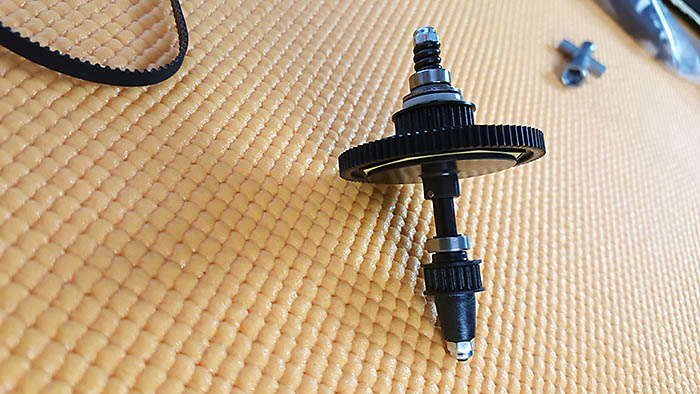
The kit includes the full time 4wd pulley to be mounted to the other end of the slipper shaft. TLR also offers (sold separately) a clicker assembly, that can be installed in place of the 4wd pulley. This clicker pulley allows the driver to adjust front to rear braking bias, kind of. So here’s how the clicker works. With the clicker installed, a loose setting allows the front wheels to spin freely when applying full brake. The tighter the clicker is set, the less the front wheels will be able to spin under full braking. This, of course, only affects braking the vehicle. Both wheels will hook up while under acceleration. So to summarize, the clicker is in no way a center differential. So what is it? It’s more of an adjustable One-Way-Bearing, which is allowed to spin one way but not the other. One more thing! If you decide to purchase and install the clicker unit, there will be an adjustable nut on both sides of the slipper shaft. One will adjust the slipper clutch, and the other will adjust the clicker assembly.
Steps A8 – A12
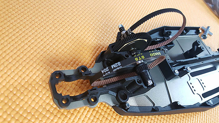
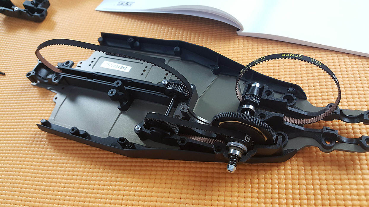
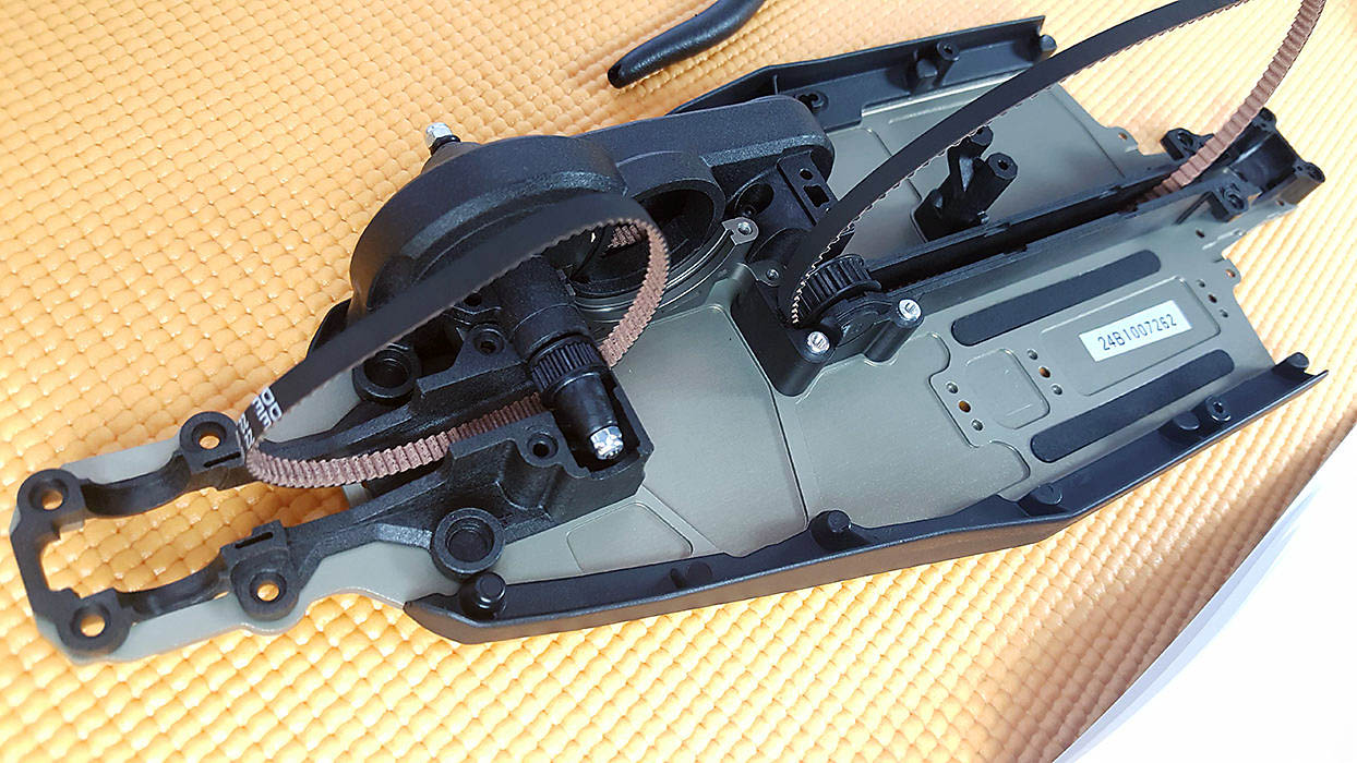
After fitting the front and center belt around the slipper shaft, it drops right into the sub-frame.
Building the jack shaft, I ran into another mis-labelled parts bag. Oh well, the build must go on.
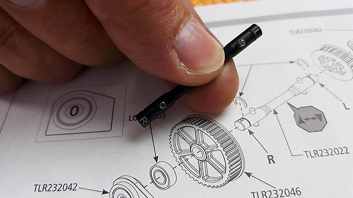
The Jack shaft has a small “L” and “R” on the ends of the shaft. Even though the two ends of the shaft look similar, it’s important it is oriented correctly.
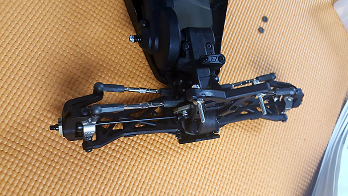
As you can see in the photos, we’ve got all the belts in place, with the jack shaft installed. When screwing down the center belt cover, I noticed I didn’t line up one of the belt inserts correctly and needed to adjust it. Once the slipper assembly is installed correctly, the center cover fit perfectly, and I screwed it down tight.
All belts are now locked into place, so there’s no chance they’ll fall out while assembling other parts of the buggy.
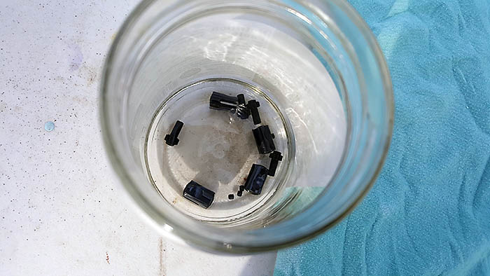
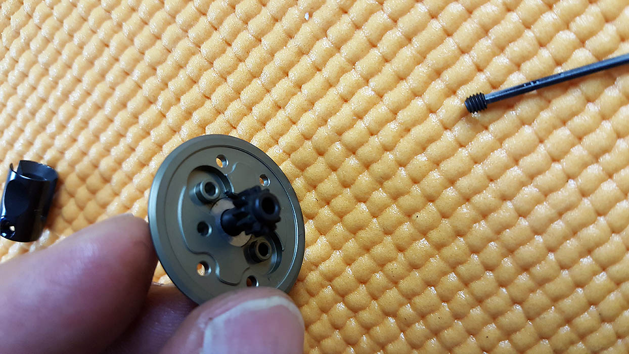
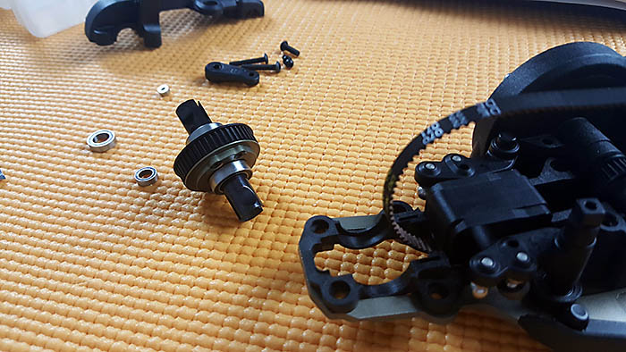
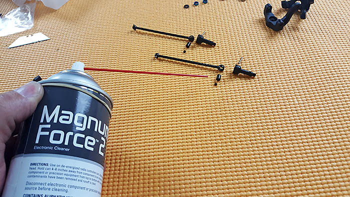
Cleaning the Diff Parts
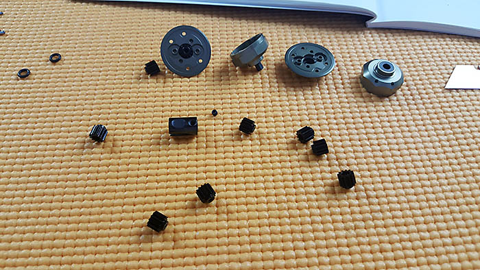
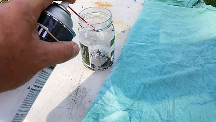
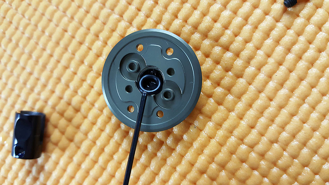
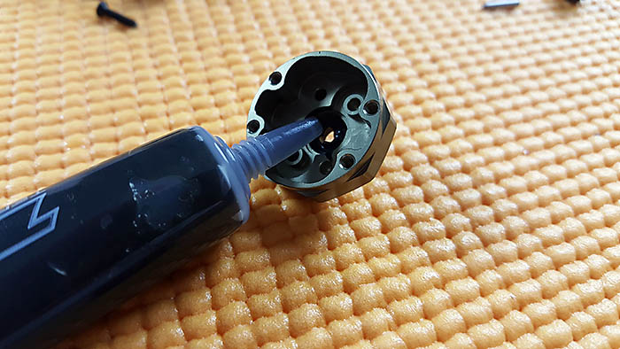
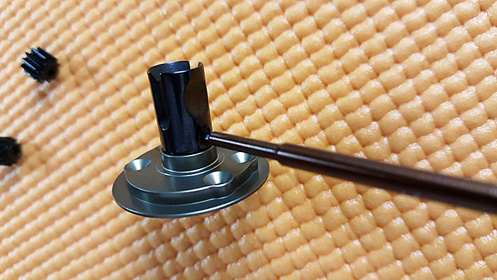
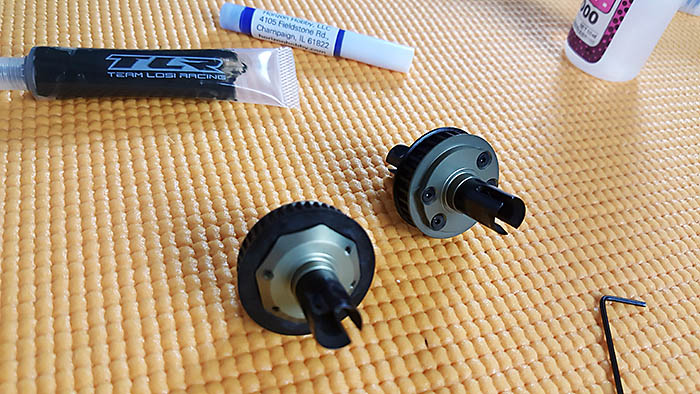
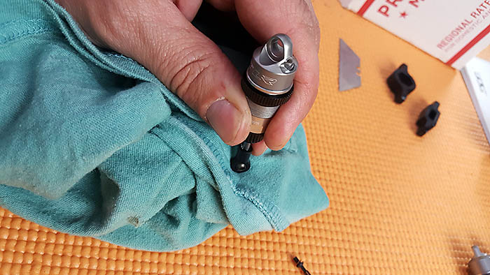
Assembling the differentials isn’t difficult, but requires some additional steps. All the set screws, outdrive cups, and output shafts (shaft with sun gear on one end) need to be cleaned with a powerful degreaser. I used Dynamite Magnum Force 2, and it did a great job getting all the oil off of the metal parts.
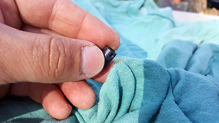
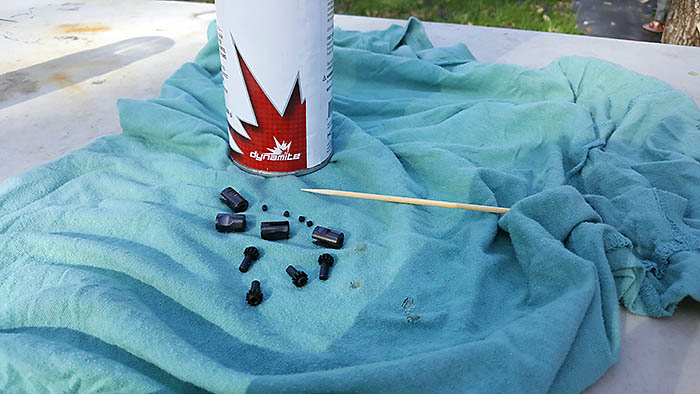
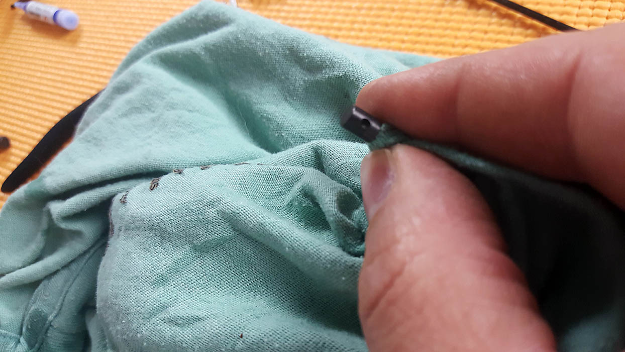
I started by placing the parts into a glass jar and spraying them with the cleaner. After swirling them in the jar, I dumped them onto an old T-shirt and made sure I got all the oil off of them. Using a wooden skewer, I was able to get the inner female screw threads, found inside the out-drive cups, nice and clean.
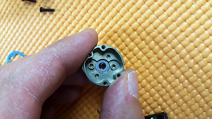
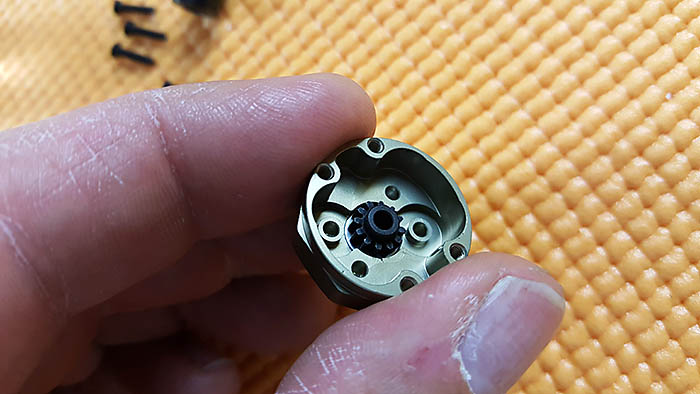
Steps B1 – B12
Now I’ll be the first to admit, I sometimes don’t pay attention to what I’m doing, and building the first diff was a good example of that. I forgot to put the small shims in-between the black O-rings and the sun gear, found at the end of the output shafts. Unfortunately, I didn’t notice this until I had one diff completely assembled. I noticed four shims lying on the table when I knew there should only be two remaining.
I disassembled the diff, but on the last outdrive cup, I stripped the set screw. Well, I guess my cleaning job was a success because the thread locker certainly worked. I ended up having to drill the set screw out of the outdrive cup, and thankfully none of the threads were damaged in the process. I also had another set screw I stole from a pinion gear that I wasn’t using, so it all worked out in the end.
The kit calls for 50,000 oil in both front and rear differentials. I used a different setup that we’ll talk about in the set-up article.
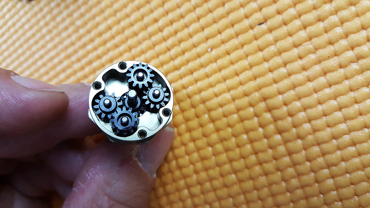
One thing to note, The four planetary gears need to be correctly oriented. Two face up and two face down. The manual clearly shows this in the images. Paying close attention to the images of each step makes assembly a snap.
Steps C1 – C9
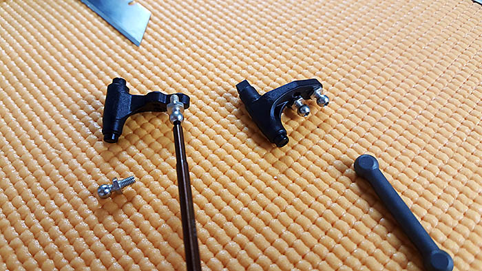
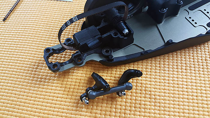
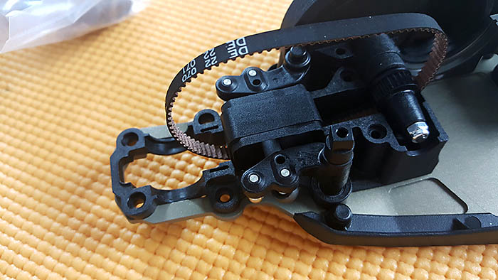
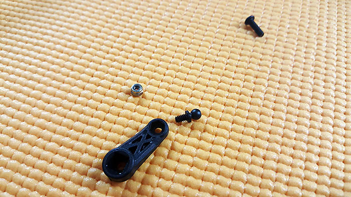
After inserting the rear differential and rear belt cover, I screwed the ball studs into the steering bell cranks.
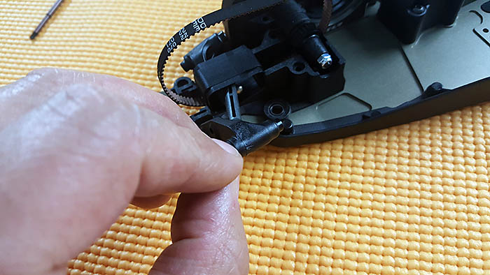
The 22-4 ackerman link rides inside the front belt, and to protect the belt from hitting this assembly, a plastic tunnel is used. It easily snaps into place inside the front belt loop and the steering assembly then is fitted inside the tunnel. This setup is actually pretty genius and works flawlessly.
Next I installed the front belt cover and front plastic steering horn.
Steps D1 – D5
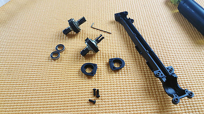
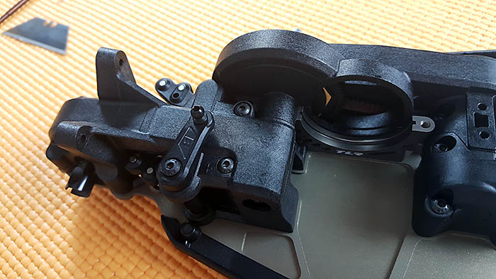
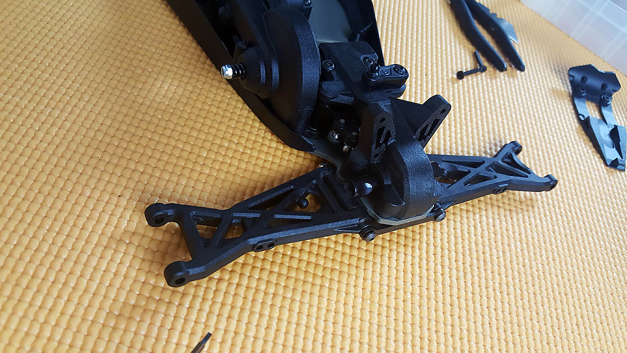
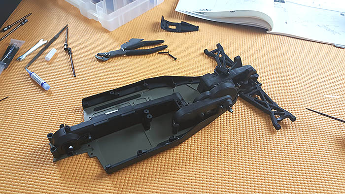
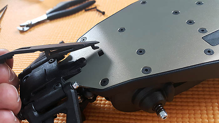
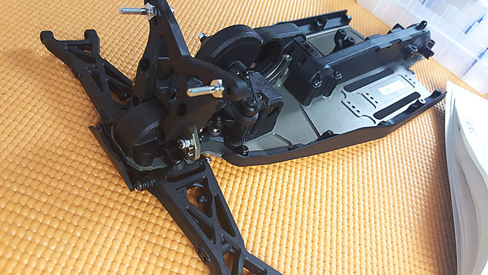
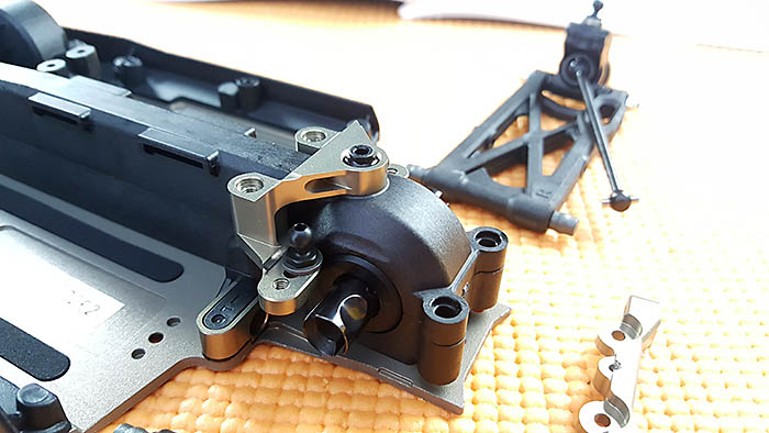
You can tell the engineers over at TLR were trying to get the center of gravity as low as possible in this buggy by looking at how the front differential protrudes through the chassis plate. The front pivot block protects both the differential and belt, while a front bumper adds further protection. The front bumper clips in at the rear and two screws secure the front.
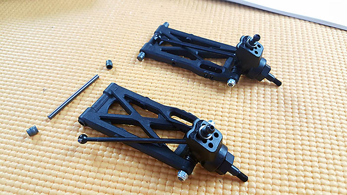
After inserting the front suspension arms, a steel pivot brace helps secure the hinge pins and adds rigidity to the pivot block.
When I first assembled the front suspension arms, the left one was binding just a little. After removing the arm from the buggy, I inserted the hinge pin into the arm to see if the hole needed to be reamed. It didn’t. Upon further inspection, I noticed the arm rubbing the pivot block. A small file was used to smooth both the arm and pivot block in the problem area. This solved the problem and the arm moved freely after that.
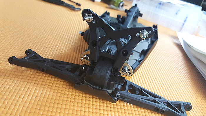
I’ve got to say, I really like the design of the shock towers. They are both designed with strength in mind and it shows.
The front camber block is aluminum and offers five inner front camber link positions.
Steps D6 – D7
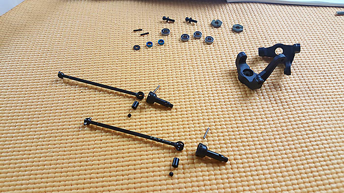
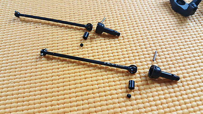
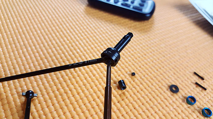
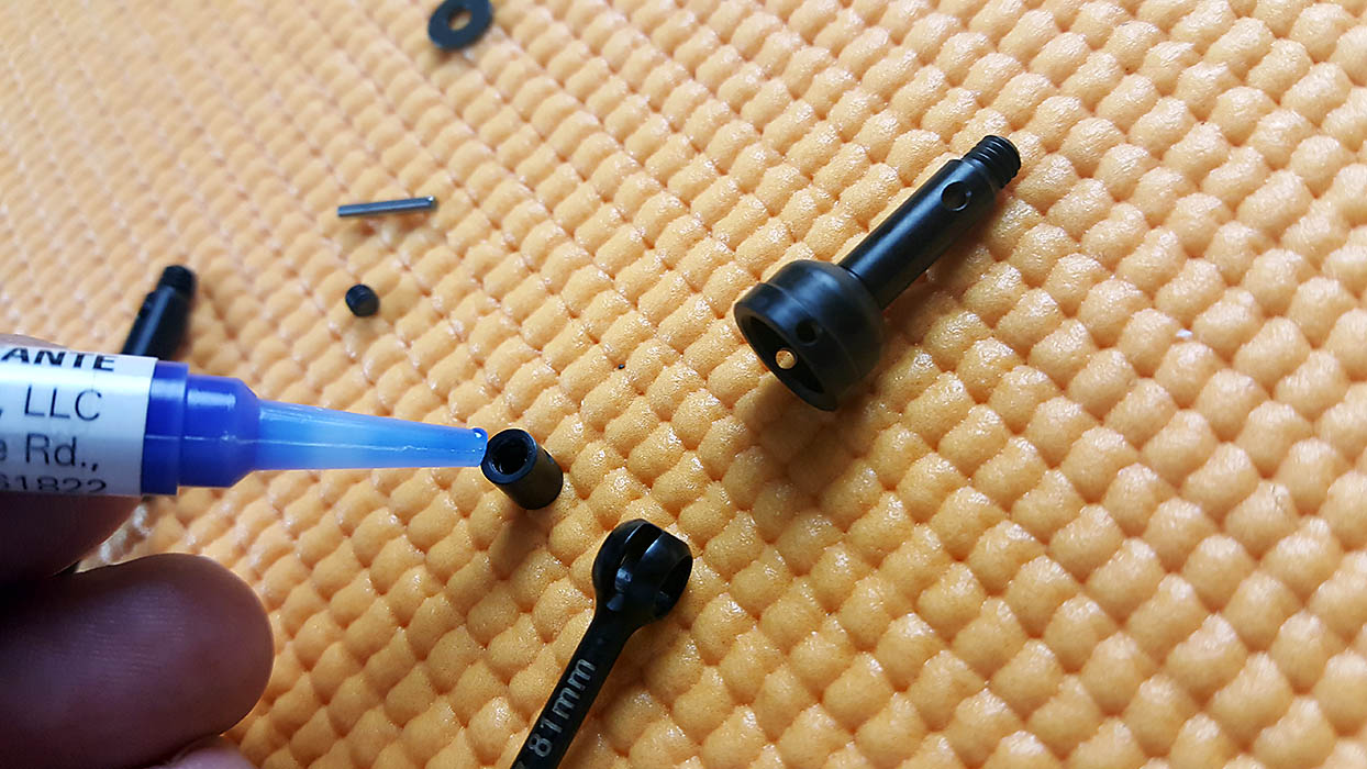
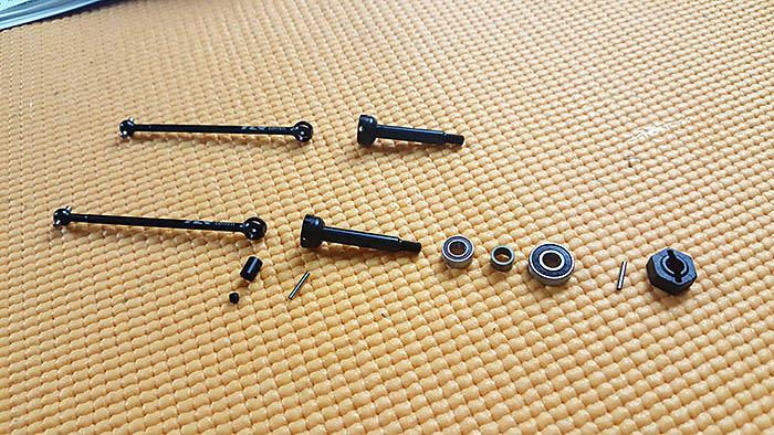
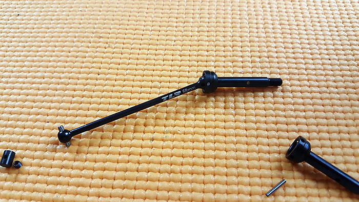
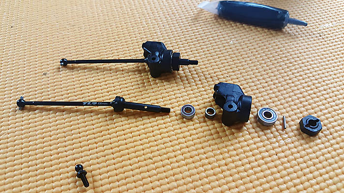
The front CVA drive shafts were a breeze to assemble. A little Magnum Force 2 to clean the set screws and female threads found in the joint “barrel” did the trick.
Applying a small amount of black grease will help keep the joint running smoothly for a few races, before they need cleaning.
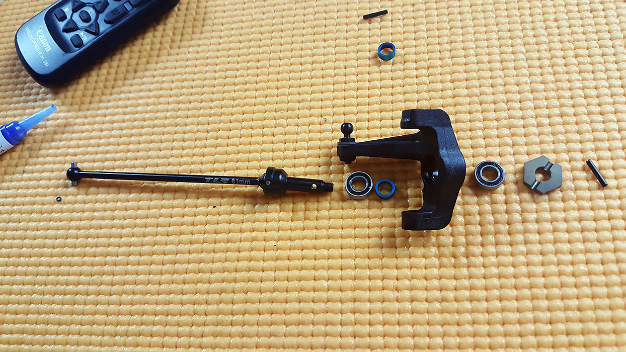
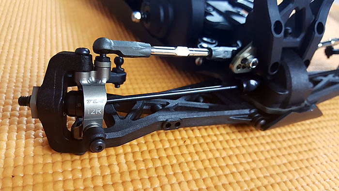
Steps D8 – D14
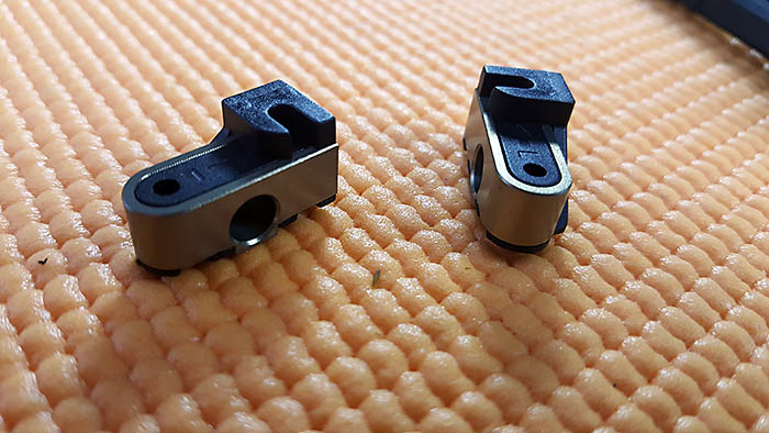
The front kit caster blocks are machined aluminum 12ş caster blocks. We modify these caster blocks in the set up article, using a Dremel and cut-off wheel, but we’ll talk about that in the setup section of the carpet track article.
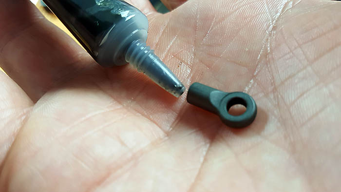
The front camber links were a bit tight to thread, but a small amount of black grease inside the ball end threads helped tremendously. The manual gives an exact setting in millimeters for each turnbuckle on the kit.
Steps E1 – E3
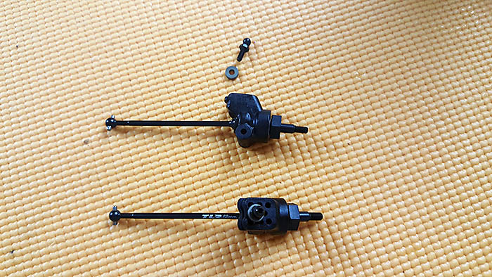
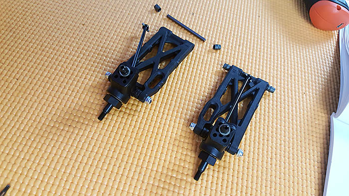
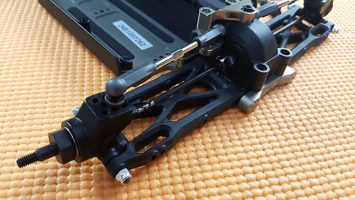
The rear CVA axles assemble just like the front axles, and the rear hubs are plastic. The ball stud screws into the top of the rear hub and has 8 different mounting positions. An aluminum spacer is used beneath the ball stud to help level out the camber link. Replacing this spacer with a larger one, or removing it altogether allows the driver to alter the buggies roll center.
Steps E4 – E10
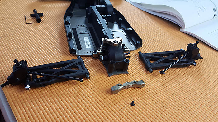
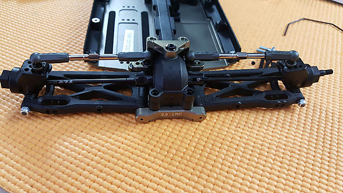
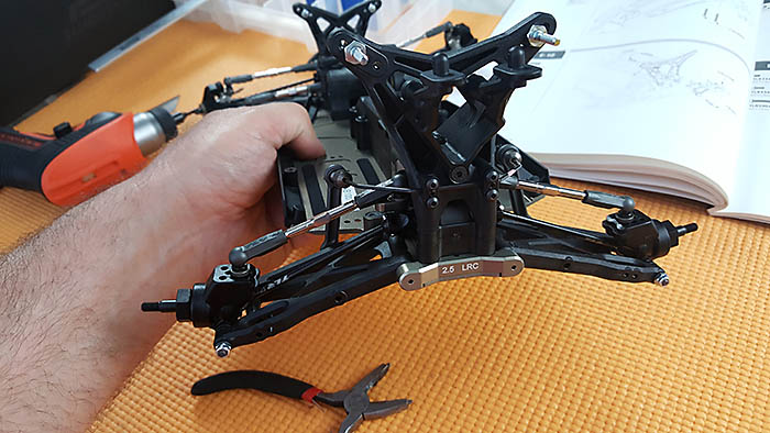
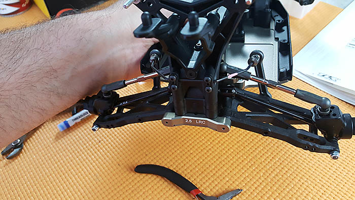
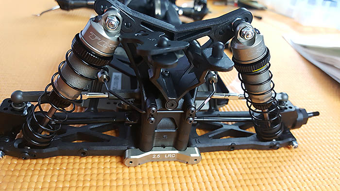
The low roll center pivot blocks are built with the 2ş anti-squat clips per kit setup. The kit also includes 1ş, 2.5ş, and 3ş LRC anti-squat clips so you can fine tune the rear grip.
The machined aluminum rear pivot block offers 2.5ş of rear toe-in and other rear pivot blocks can be purchased separately, if you want to change the rear toe. All three pivot blocks included with the kit, two in front of the rear arm and one behind the rear arm, are for low roll center. Changing the rear of the buggy to high roll center requires buying all three pivot blocks, unless you change the rear roll center using the rear camber link angle. This can be done, but changing it at the pivot blocks is actually more effective. High roll center clips will also need to be used if switching to high roll center. I think I’ll stick with the low roll center for the time being.
I really like how the rear suspension arms are locked into place and the quality parts found throughout this kit.
The rear camber block is also beautifully machined aluminum and offers three rear inner camber link mounting options.
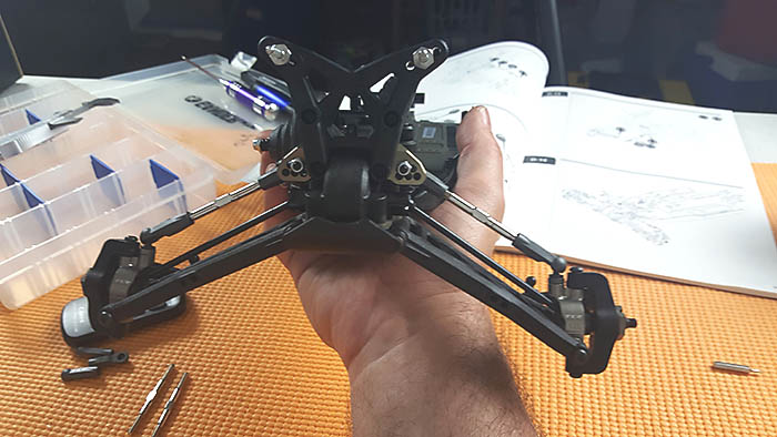
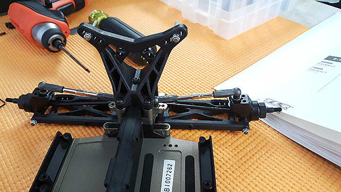
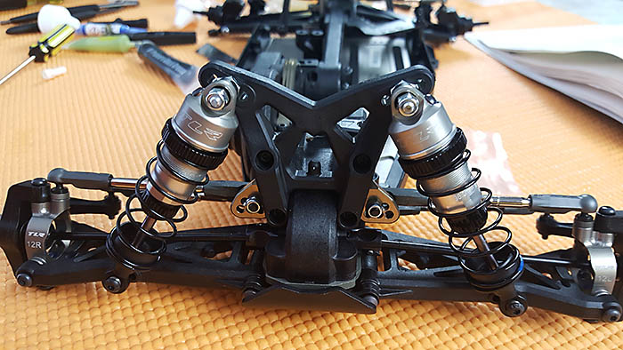
Next I’ll install the rear shock tower, and I’ve got to say, it is impressive. Not only is the plastic high quality, the design is superb. I like how TLR went with a triangular design for strength, but still kept weight management in mind. It not only looks beautiful, it looks incredibly sturdy.
Steps E11 – E13
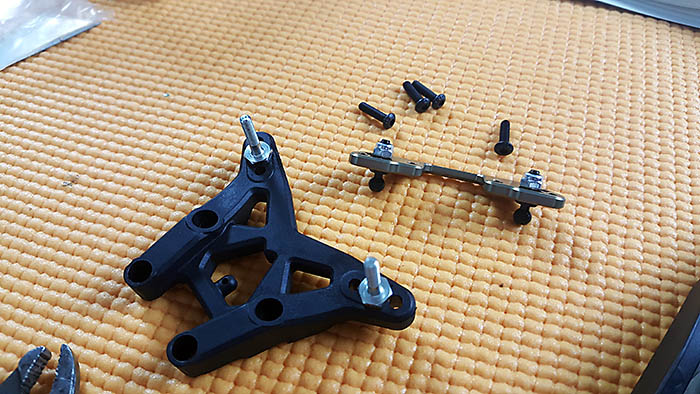
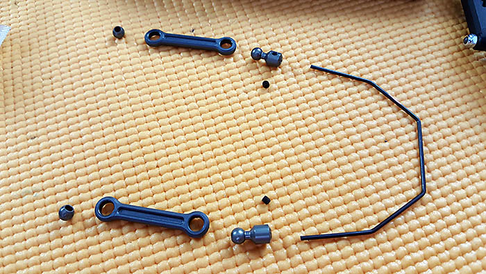
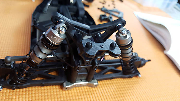
The 22-4 2.0 comes with a rear pink sway bar. Pink is a pretty stiff setting and will offer a lot of stability. The sway bar is pretty straight forward and went together in a snap. I set the ball ends flush with the sway bar and applied thread locker to the set screws.
Two addition set screws are used to remove slop, and it’s important not to over tighten these screws. Too loose is much better than too tight here. If the little set screws inside the rear mounts are too tight, it won’t allow the energy to transfer to the other suspension arm and defeats the purpose of the sway bar.
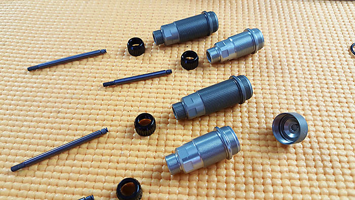
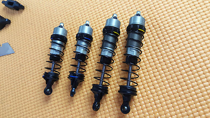
Steps F1 – F7
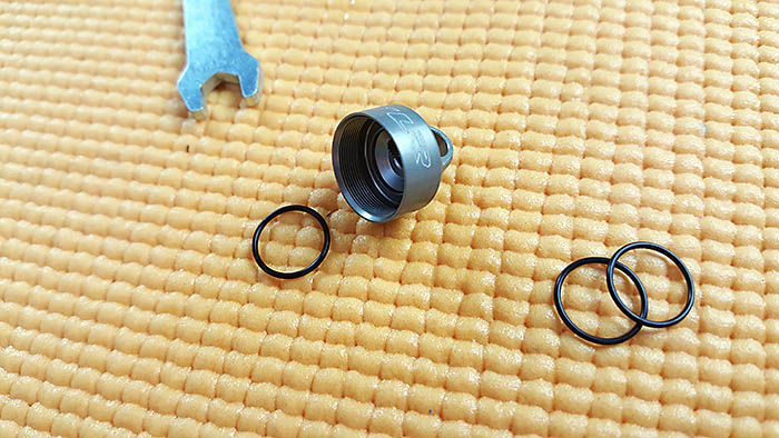
The kits comes with a set of shock tools, shock body wrench and shock cap wrench, which makes it easy to tighten the shock cap without scratching the anodized finish. The front shock bodies are a bit lighter color than the rear, though you can’t really tell with the springs mounted, as all four caps match in color.
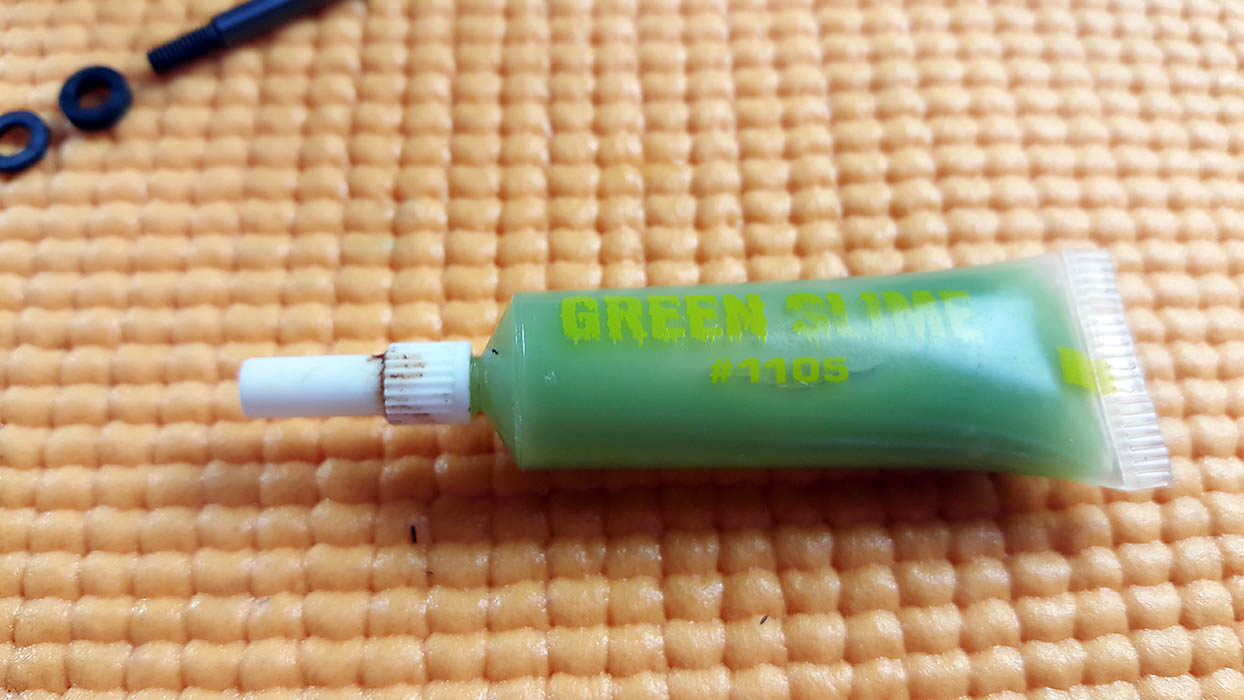
I used a bit of green slime on the O-rings and seals to ensure they don’t leak.
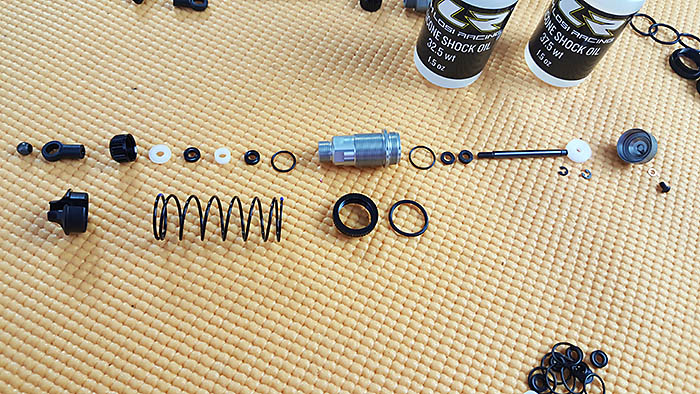
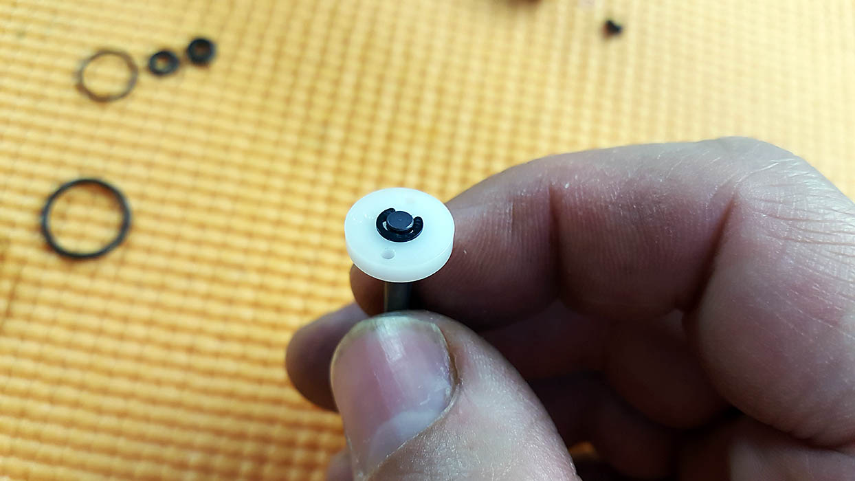
The machined pistons used in the 22-4 2.0 are 2×1.5 in the front and 2×1.7 in the rear. Each piston is held on with two E-clips.
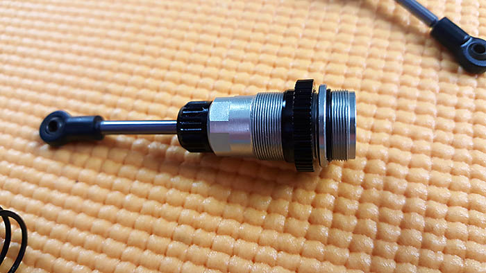
After filling the shocks with oil, tightly screwing on the shock cap, and inserting the copper washer onto the small bleed screws, I compressed the shocks slowly. When the shock was fully compressed and a small amount of oil leaked out of the bleed hole, I inserted the bleed screw and tightened it down. If no oil squeezed out of the bleed hole with the shaft fully compressed, I needed to remove the shock cap and top off the oil, because it wasn’t full enough.
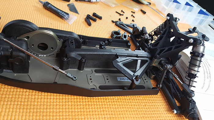
Steps G1 – G11
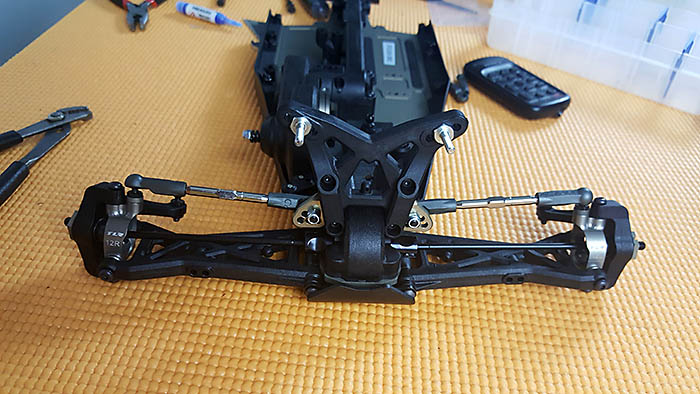
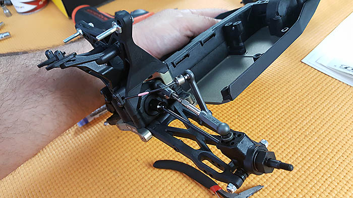
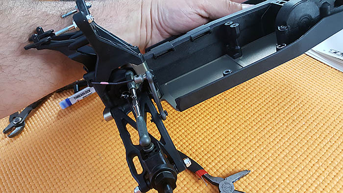
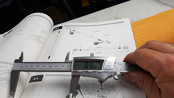
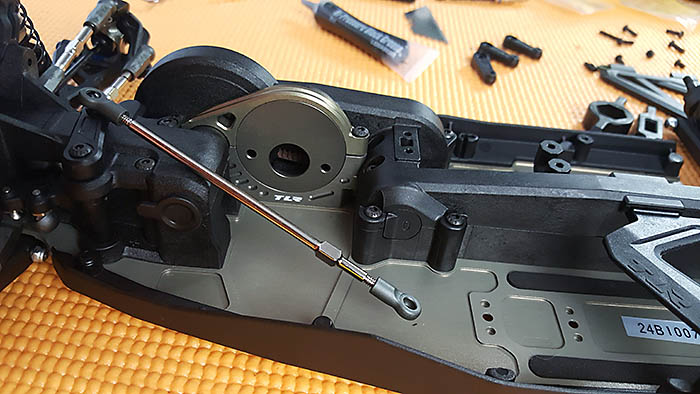
We’re almost done with the build, but there are still a few things needing to be assembled. With the steering servo so far back in this buggy, a long turnbuckle is needed to connect the front servo horn to the servo horn on the actual steering servo. Installing it was a breeze.
To install the body posts, a long set screw is screwed into the chassis, from the top, then the body post is screwed onto it. Because the kit can run a shorty or saddle packs, two battery retainers are included, though I only needed one for the shorty configuration. The body post also doubles as a battery strap post. A small block is installed either in front of the battery for a rear battery setup, or behind the battery for a forward battery setup. I’m using a forward battery setup.
Steps G12 – G14
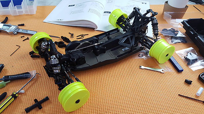
A full set of fluorescent yellow wheels are included with the kit and are ready for me to clean them with some Simple Green, then mount the tire of my choice. We’ll talk more about that in the setup portion of the carpet race article.
I noticed when assembling the front axles, several steps ago, that the front axles were shorter than normal, but it wasn’t until I saw the front wheel nuts that it truly sank in. Wow, these things are shallow! It almost looks like half the nut is missing, well not really, but that is how tall it is. I can, however, understand why they used such a short front axle and nut. They wanted to get the tire as far over the steering knuckle radius point as possible. To accomplish this, they needed to move the wheel mounting point as far out on the wheel as possible. So, with the front wheel mounting point as far out on the wheel as possible, a regular axle and nut will stick out too far, catching on everything as you go by. While this isn’t exactly a deal breaker by any means, I kind of like being able to just throw a regular sized wheel nut on any corner of my vehicle, if I ever loose one, though I don’t think I’ve ever lost one. Oh well, I guess I’ll just get over it and move on. Lol
Build Summary
Building the TLR 22-4 2.0 was enjoyable and beside from a few of my own mistakes, went extremely smoothly.
The only parts in the entire kit that even bound at all, were the front pivot block and front left suspension arm. A small amount of filing was needed for smooth operation.
Everything else fit perfectly. The ball cups on this kit are excellent, free movement, yet secure. The shocks are very smooth and were easy to build.
While the belt system may seem complicated, it really isn’t. It’s actually pretty straight forward and I think they did a good job of working the steering bell crank system through the belt.
The only thing I really don’t like about the kit so far, is having to remove the steering servo to get the center belt cover off. The center belt cover is the cover that goes over the slipper clutch and spur gear. I know, you also need to remove the front shock tower and front belt cover to get to the center belt cover, but that doesn’t seem to bother me. Having to remove the steering servo is actually the only thing that bothers me about the system, I guess because it was such a pain to neatly tuck my wires in front of the steering servo. Oops. You’re not supposed to know I already installed the servo. Lol
Well look for the electronics video next to see what I’m talking about and to see what electronics I’ve chosen. I’ll also be soldering in the ESC and motor in the next article, with a video to explain how it’s done, for those of you who don’t solder.
Thanks for reading this article and keep watch for the electronics article (next) followed by the body painting article, carpet stock racing article, carpet mod racing article, clay track racing article, dirt track racing article, and the TLR 22-4 2.0 summary article.