by Kraig Obrien
Team Losi has released their third generation of the 22 2wd off-road buggy appropriately called the 22 3.0 in November of this year. Other than a few pieces, this is as close as you can get to a new from the ground up kit. While the parts carry over is nice for those that have the 2.0 version of the car, those who wanted a completely new car will have to wait.
A little history lesson here. The 22 series of the 2wd buggy was released back in 2010. In fact, it was around this time that TLR, a.k.a. Team Losi Racing burst on to the scene. Sure Team Losi has been around prior to 2010 but for a few years they went into a hiatus of sorts and were not extremely active in developing and releasing 1/10th scale racing machines to the public. That all changed in December of 2010.
The 22 1.0 and 2.0 versions allowed you to build the car with a mid motor setup or a rear motor setup. It was almost as if you had two cars in one kit. However, you didn’t have two complete cars because it took some work to convert them between rear motor and mid motor. That has changed with the release of the 3.0. This car is intended to be a mid motor only car so all of you rear motor fans, better pickup the 2.0 version while they are available!
I am not going to go into detail of every step of the build process but rather touch on things that I felt are important enough to help make your build easier. That might be clarification of what you see in the manual, a different way to build something or something else. Keep in mind that what you are about to read is my opinion and you can feel free to disagree with them because I won’t be offended.
Ok, time to get started on the build. You will find bags marked by an alpha character and inside those bags you will find more bags. It is normal to find 3 plus bags inside the main bag. Most of the time you will find one hardware bag inside the main bag but there are situations where you will have more than one hardware bag so you may have to open more than one bag at a time.
On most kits that I have built I recently they have you install the servo horn perpendicular to the chassis, i.e. straight up and down. Instead, they have you install the horn one spline off from dead center. Here you have the option to install an aluminum servo horn rather than the plastic piece. I installed this part because honestly, I have been known to hit a few pipes and I don’t want to have a d.n.f. because of a stripped servo horn. Instead, I will put my fate in the hands of the servo holding up.
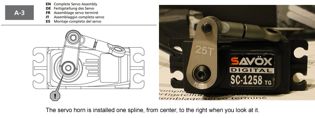
Optional Servo Horn installed.
Moving along in the build you will find the plastic is made out of different material meaning some of it is softer and some of it is stiffer. The side guards, or mud guards as some like to call them, is the first part I came across that was different. So be careful when you install the screws as it will be easier to strip out some of the holes if you are not paying attention.
When it comes time to installing the servo you will find new servo mounts which means the 2.0 servo amounts will not work but the plastic ones will work just fine. What is missing in the manual is the number of shims you need to install for your servo. Frank Root has said that this was an oversight and it will be corrected in future manuals. In the meantime, I setup mine up so the linkage was parallel to the steering rack which is installed in the next few steps.
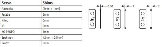
Servo Spacing Chart
A quick comment here about the parts in bag B-1. The wheel hex on the 3.0 is now 12mm whereas the predecessor’s were 10mm. You can swap the front axle between cars so you can use your existing wheels if you had them. The screw that holds it all together is easy to access from the backside thus not making it a major task.
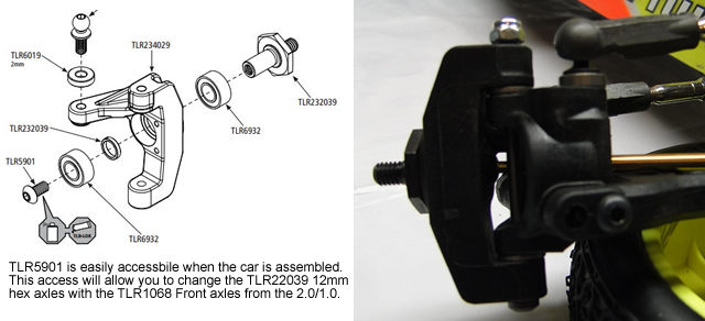
Swapping the front axles
When you get to bag B-2, you are installing the spindle onto the carrier. With the supplied washers you can move the height of the spindle up or down which will have different affect on the car. I bring this up because when I assembled the parts together it was a tight fit. This is actually a good thing because I would rather have it tight and do some minor hand fitting. Of course, if it was a perfect fit that would be preferred but I will take tight over loose any day.
Moving on to step B-3, you are assembling the front suspension arms. I wanted to let you know that if you haven’t picked up a reamer by now you should. I always ream my suspension arm and caster block holes. This helps free up the movement of each piece. I did find that very little, if any at all, material was removed from the inner suspension arm mount.
Now I do have a complaint about the how the caster and spindle assembly mounts to the front arm. Instead of using a full length hinge pin to attach the caster and spindle assembly to the arm you have to screw in the king pin screw. Pay close attention here because one, the screw has to go in straight and two, the shoulder extends past the arm and can cause a bind in the movement of this assembly. I know they brought back the VLA in the 3.0 kit but there must be some reason why they went with this setup rather than using a full length pin. It probably has something to do with using e-clips and people saying that it is old school technology but still, this keyboard engineer would rather have an assembly that didn’t rely on me installing a screw straight. Ok, enough of that, just pay close attention to those two things. If you get it wrong, they say it will free up but on mine, it is still tight after at least 8 runs.
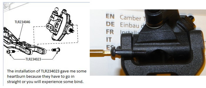
Front Carrier Assembly
Bag B-4 is the assembly of the camber links. Here are a few things that will help you make the build of these things a little easier. First, take the ball cups and your reamer that you use to make the holes in your body and carefully remove a little bit of material where the link is inserted into the ball cup, it doesn’t take much. This will help you install the link into the ball cup straight. Before you start the assembly place a little bit of diff lube or wax on the threads of the camber link. I will then install the ball cup into my drill and then turn it on and carefully thread the camber link in and out a few times. By doing this it will free up the assembly allowing you to make adjustments when it is installed on the car making adjustments. I did this for each link I assembled.
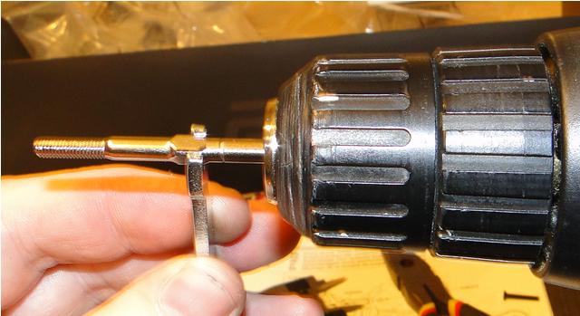
Camber Link Assembly Option
The assembly is pretty straight forward until you get to bag C-2 which is the assembly of the rear suspension. Be sure to ream through the holes and test fit the parts. I will say this about the entire car and not just the rear suspension, the inclusion of the aluminum washers is a nice touch. However, when you have two like parts i.e. aluminum and aluminum, never let the aluminum make contact with the other piece of aluminum. By doing so, you will experience excessive wear on the aluminum pieces which you do not want. I hate to say this but I am speaking from experience so don’t make the same mistake I did.
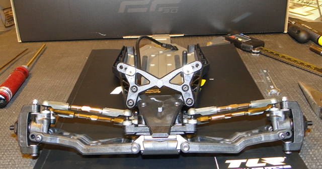
Completed Front Assembly
When you get to bag C-4 you will notice the rear shock tower is angled which is hard to see in the manual. So when you look at the shock tower from the side, the top of the shock tower will lean towards the front of the car. This interesting concept allows the shocks to be almost straight up and down when installed on the car.
Moving along to the differential assembly, D-1, I always sand my diff rings with 600 grit sandpaper. I do this because I feel it gives me a differential that will last longer than if I didn’t sand them. I first color the rings with a sharpie so that I can tell when all parts of the diff ring have been sanded. It is a tedious process but in my eyes and pocket book it is well worth it. I should tell you that I found that I had to run the differential really tight, probably tighter than any other car that I have had in the past.
When you get to bag D-5, we need to do some work on the Layshaft. You will notice that where the nut is installed to tighten down the slipper. Remove that long set screw and put some lock-tight on the threads. I didn’t do this and when I was adjusting my slipper this long set screw came out of the Layshaft. I would do this now rather than when you are at the track and missing out on some track time.
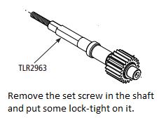
Lok-Tight
One last thing that I want to mention is be sure to compress the spring, both the differential and the slipper, multiple times. This helps break in the differential and slipper because the springs will have already been stressed. So the less chance of you burning up your differential or glazing your slipper pads.
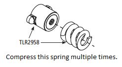
Compress this spring.
Now for the shock assembly. The shock o-rings are an important part of the shock because if it tears you will most likely have a leaking shock. So here is where I strayed from the manual’s instructions on how to build them. Instead of assembling them in the shock body as shown in the manual, I will carefully place the shock shaft with the piston already on the shock shaft, in the body and down through the bottom of the shock. I will then lube the shock o-rings and the plastic bushings before placing them on the shock shaft. By doing it this way, I feel I have less of a chance of tearing an o-ring or damaging the plastic and then I will install the cap. Just be sure that you don’t forget to look ahead in the manual and install the internal shock limiters first. I should tell you that I didn’t use the supplied kit oil. I felt that the oil I purchased off the shelf at my local hobby shop went through a better quality control process than the kit supplied oil.
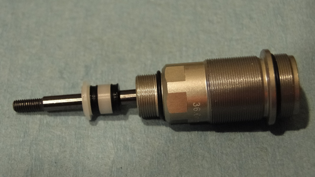
Alternative way to install o-rings
When you install the balls in the lower shock eyelet, look at the plastic eyelet and look for the side that is flat. You can usually tell which side is flat because it will have a mold ring around it. Install the pivot ball on this side of the eyelet as this will ensure free movement of the pivot ball in the shock eyelet.
Other than those few items I pointed out the build should be pretty straight forward. Just be sure that nothing binds in the suspension and you should have a great running car. Also, whenever you build or rebuild a differential, don’t forget to double check the setting after a few laps on the track. This way you do not prematurely wear out the parts on your car.

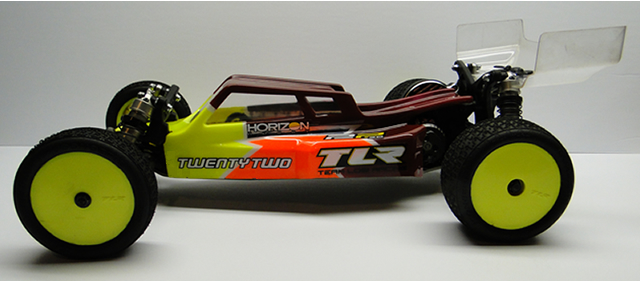
Almost complete
Now that the car is built and you have installed the electronics where does that leave us? Well, it leaves us with a car that offers almost every tuning option one could ask for. I say almost because it is only a mid motor car. Will that handicap the car on loose tracks? I honestly don’t think so based on what I experienced when I hit the track with this car. With the kit setup I experienced a lot of rear bite, more than its predecessor the 2.0. I don’t have the luxury of running it outside right now because of the weather but, I feel pretty comfortable I will not be at a disadvantage.
My local track hosted the Horizon Hobby Off-Road Championships in November. After a few laps with the kit setup I decided to try using Dustin Evans setup. It was an improvement over the kit setup, which I expected. It required a few additional pieces, such as shock pistons, springs and some oil which were already on the walls at Trackside Raceway.
So how did it run? Well, out of the box it ran just as good if not better than the 2.0 I had been using after I had been tuning on it for awhile. I didn’t need to add extra weight to the car to get it to feel like I wanted it to feel which I had to do with my 2.0. It felt planted in both the front and the rear. This isn’t an article to bash on the 2.0 but rather to point out the fact that out of the box the 3.0 is pretty much ready to go. The kit setup may work for you at your track but if it doesn’t, the tuning options included in the kit or the springs you have in your pit box will help you dial it in to your tracks conditions and driving style. I say this because there are not to many tracks that are the same.
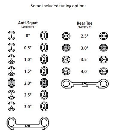
Rear Toe / Anti-Squat Pills
It seems like the latest craze is how much your car weighs. Most stock guys are trying to get their cars as light as possible. My car, with a full size servo, a HobbyWing Stock Spec 3.1 Speed Control, Motiv 17.5 M Code Motor , kit wheels, JConcepts Dirt Webs with Dirt Tech Inserts, and an Airtronics Rx-481 receiver weighed in at 1568 grams. As soon as I put on some AKA 2.4, 60mm, wheels I drop down to 1533 grams. Team Losi Racing is offering a light weight body, aluminum dog bones, titanium shock mounts and titanium tie-rods and that should help it shed some weight. You could also go with a servo that isn’t full sized to save some weight.
Ok, time to wrap this up. This car is definitely an improvement over the 2.0 in my opinion. The suspension springs and a few front end pieces are carryover from the previous generation which is nice. If you have a lot of 2.0 front wheels you can use them on this car by using the front axles from the 2.0. Team Losi Racing includes some tuning options for you, such as rear toe in options, anti-squat options, and rear axle spacers. The battery can be run in-line or transverse on the chassis. The three gear transmission has been a good fit for me and the tracks I run on. A 4 gear transmission conversion is available, TLR332054, if it isn’t already, if you need more rear bite or like how the 4 gear transmission car drives compared to the 3 gear transmission.
