|
- Team Durango - DEX410/DEX410R Gearbox Build Guide -
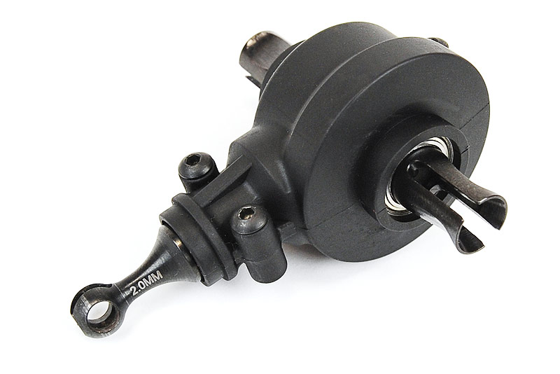
Getting the gearboxes built correctly on the DESC410R/DEX410 vehicles is critical for long-life and handling the rigors of racing. The metal gears are strong but nothing can cope with the combination of a poory built drivetrain, extreme power and on-track abuse. So please take a look at this guide to help protect your drivetrain and keep you on the race track.
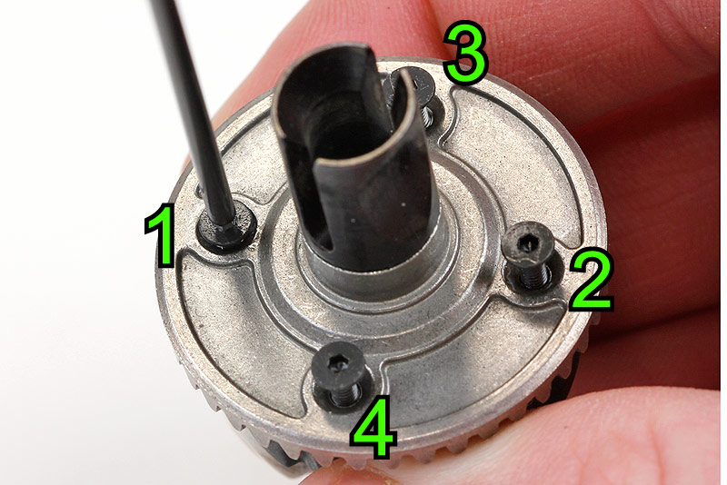
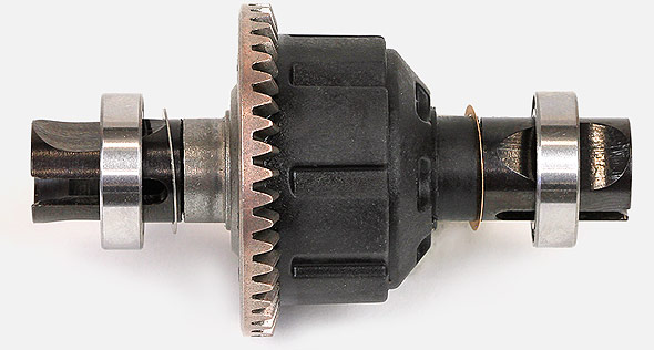
With the differential built and filled with oil, attach the crown gear half of the differential and fasten the screws down in a cross fashion. Back off all the screws a turn or two before repeating the cross pattern tightening again - this is to ensure the crown gear is sat fully in place and aligned correctly.
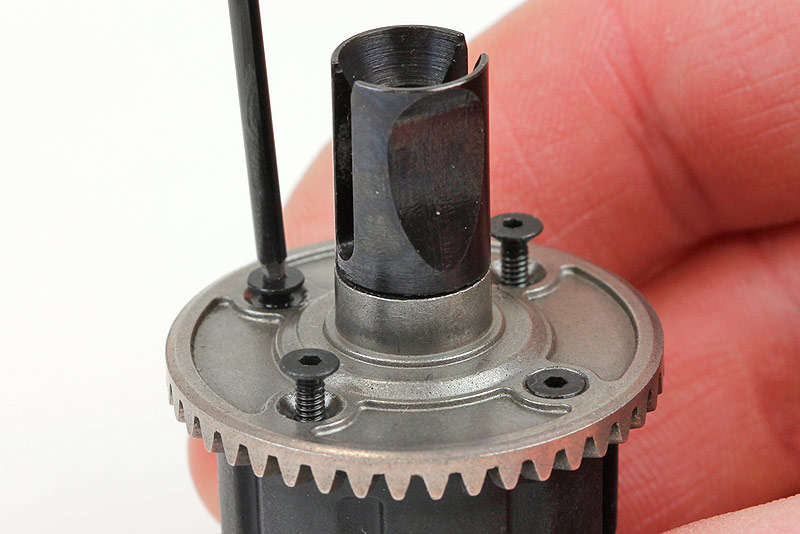
 Tighten the gears in a cross pattern.
 After the crown gear is attached - loosen the screws a little and tighten cross-pattern again.
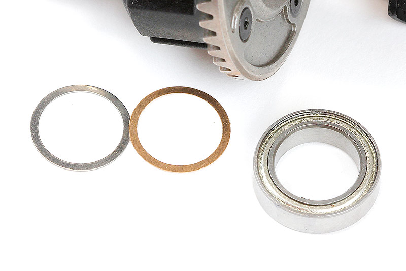
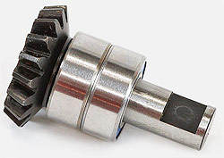
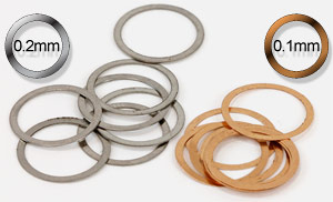 Shimming the differential correctly is an important step and this is the next stage of building the perfect gearbox. The DESC410R/DEX410 come with two types of shim for this purpose, a 0.2mm which is silver in colour and a 0.1mm copper-coloured shim.Firstly you need to know how many shims will get the diff sitting correctly so press down the bearing on the moulded diff-body side so it's fully in place as we'll use the crown gear side of the diff to play with shim settings - this is purely because it's much easier to remove / replace the bearings on this side whilst we find the perfect setting.
Start with one 0.2mm silver shim on the crown gear side and slide the bearing over the top. Place the diff with shims and bearings installed into the empty differential case and clamp the case tight between your fingers. Next you need to clamp the outdrives with your other hand, squeezing them inward whilst trying to ‘rock' the diff side to side in the case.
 One silver shim in position.
 Test the end-float in the case by trying to shift the diff sideways.
If you can feel a slight movement then you can maybe add a 0.1mm copper coloured shim to the same side, next to the previously installed shim and try again. If on the other hand your diff is hard to install or feels to be binding then you can remove / add to find your perfect balance. The shimming in this guide is for the parts we used - your shimming could be different so be aware.
 One silver shim wasn't enough in this case, so I've added a second copper shim.
 Silver and copper shims together were the right setting - now it's time to position them.
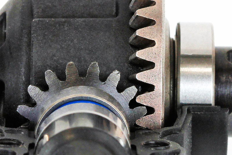
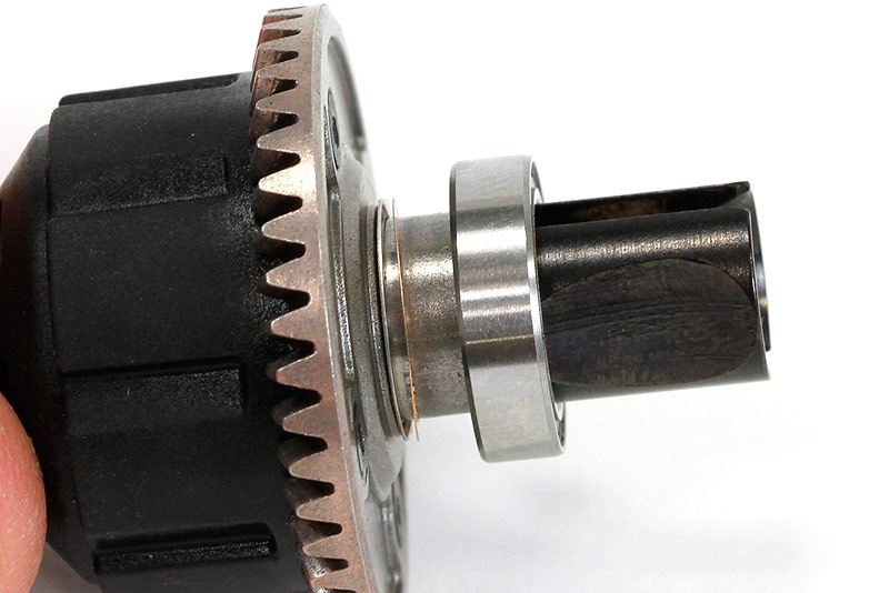
Once you've found the setting that feels right you need to test against the input pinion gear - this will define where you need to place the shims you've just decided upon. Place the input shaft / pinion gear into the gearbox housing along with the diff you've just shimmed correctly and clamp the case halves together with the provided screws and spin the input shaft. With all shims on the crown-gear side (where you should have been test-fitting them) you might find the gears are loud and have excess friction - so next comes choosing which side you place your shims.
You want the crown gear as close to the pinion gear as you can to get a good mesh - but you don't want it so close that the gearbox is notchy or excessively loud. With the example differential in the photos needing one of each shim, you could leave the 0.2mm silver shim on the crown gear side and place the smaller copper-coloured 0.1mm shim behind the bearing on the opposite side. This will shift the diff over by 0.1mm and effectively seperate the crown gear and pinion by the same amount. Re-assemble the gearbox and test as before to check how smooth the gears are - a slight roughness to the action is fine but if there's still excessive noise and friction you can continue adjusting the shims to suit.
Above: In the example above, the perfect setting ended up with one silver shim on the Crown-gear side and one copper shim on the moulded side.
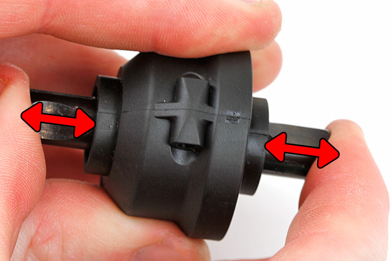
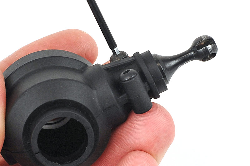
 With the differential shimming complete the last point to look at when building your DESC410R/DEX410 is the input shaft itself. Simply tightening the CVD-shaft onto the input shaft and placing it into the gearbox housing could result in some degree of movement. You can check this by clamping the gearbox together very tightly with your fingers or screwing the halves together - then with the unassembled CVD attached to the input shaft, try to rock the shaft vertically up and down (see photo). The movement, if any, will be slight - but this is amplified inside the gearbox and will result in the teeth of the gears having an improper contact patch which will place excess strain on the gears.
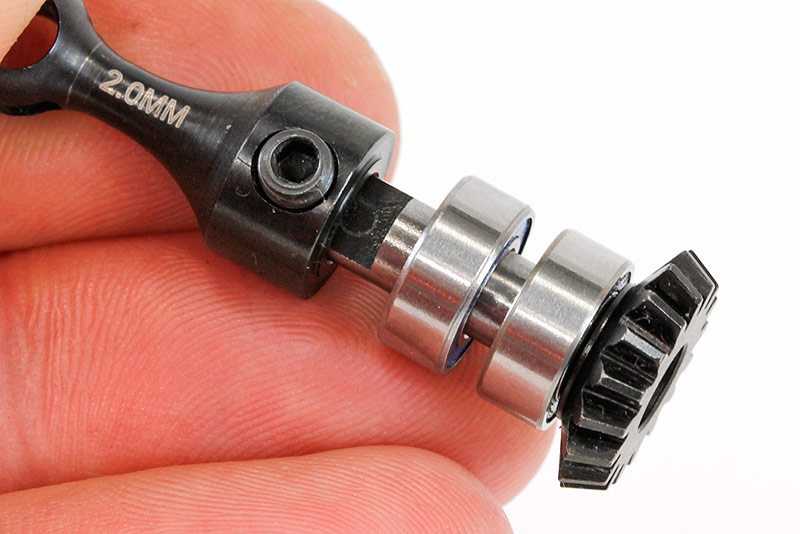
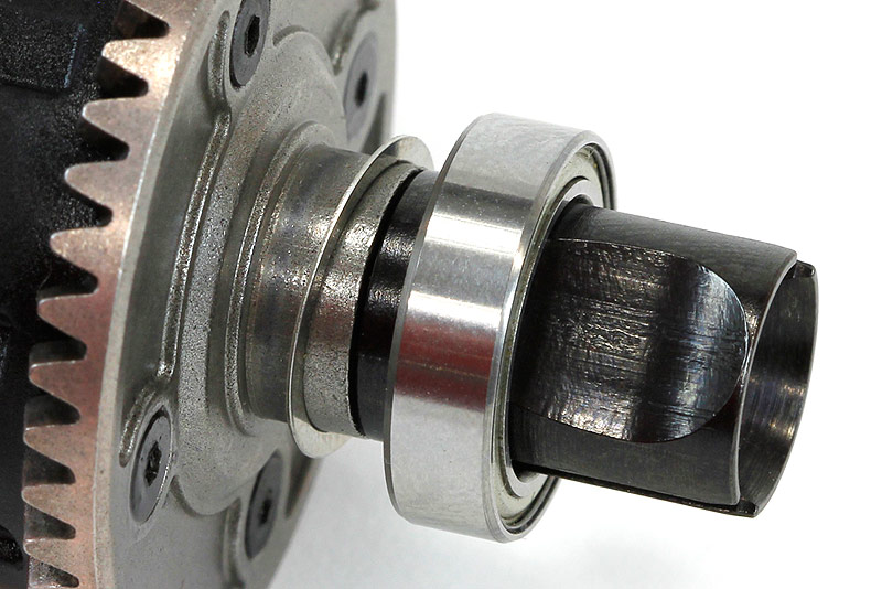
Input shaft with bearings in place.
Tighten the grub screw whilst applying pressure to squeeze the two halves together.
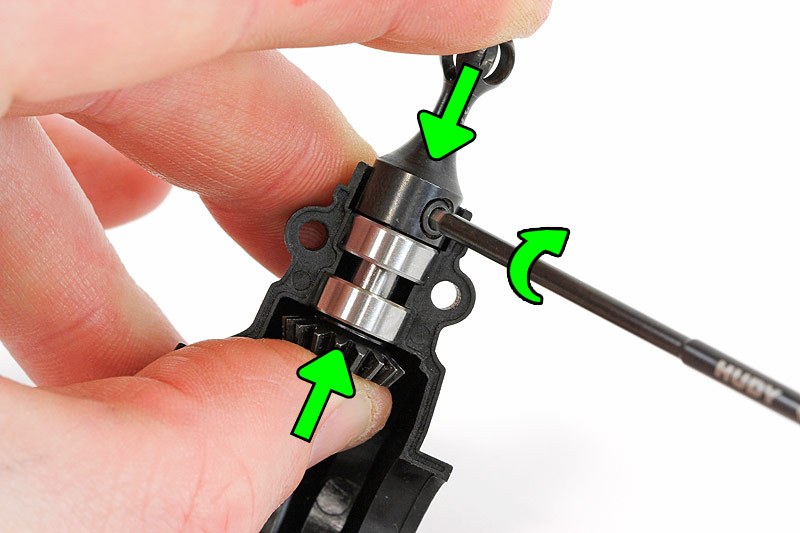
To get the perfect setting and eliminate any play in this vital area you need to loosely join the CVD shaft to the input-shaft and place them into one half of the gearbox housing. Clamp the two metal parts together so you're pushing the CVD and input shaft together and squeezing the bearings against the plastic divider. Carefully tighten the grub screw on the CVD part of the assembly whilst applying the pressure and test the input shaft for movement again.
Tighten the gearbox screws TIGHT to help clamp the bearings.
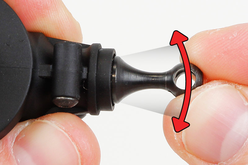 With an improper setting the input shaft will be able to rock up & down slightly - it's hard to detect with the full driveshaft in place.
Adjusting the amount of pressure applied during tightening will vary the setting - when you get it right the shaft should be firmly set and free from any play. If you apply too much pressure you might find the bearings binding slightly, so try again. The perfect setting should see minimal binding of the bearings but a totally rock-steady shaft.
Your gearbox should now be ready for the track - time to build the other one the same!
Source:


|