Team Durango has recently released the Durango Injection Moulded Engineering Composite (DIMEC) chassis for the DEX210 buggy.
Here we show some hints and tips that may prove useful when changing from the aluminium chassis to the DIMEC chassis on your DEX210 buggy.
Which DIMEC chassis?
There are two versions of the DIMEC chassis for the DEX210 model, the original DIMEC chassis and the DIMEC20 chassis. The part numbers are:
TD320163 DIMEC DEX210 CHASSIS (+8mm)
TD320220 DIMEC20 CHASSIS DEX210 (+8mm)
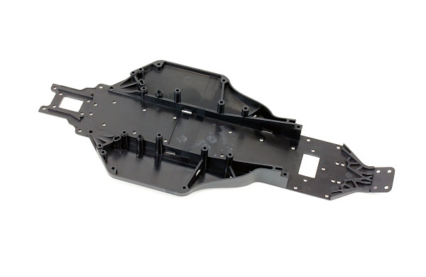
The DEX210 DIMEC Chassis
These chassis are both moulded from an engineering composite material. The difference between these two chassis is the composition of the material used in the moulding. The DIMEC20 chassis is stiffer than the DIMEC chassis, at the expense of having little more weight.
Which chassis you should choose depends on the surface and/or the climate where you will be racing. For slick, slippery surfaces or for use in cooler environments the more flexible DIMEC chassis may prove to give more overall grip and give more consistent performance, whereas on high grip surfaces or in hotter conditions the DIMEC20 chassis may prove to give more consistent performance and faster lap times.
Body
The DIMEC chassis is both longer and also a little wider than the original chassis on the DEX210 model, so the original DEX210 body will not fit.
Team Durango has bought out a new body specifically designed for the DIMEC chassis. This body also features a forward cab design for more steering, and more stability in the air.
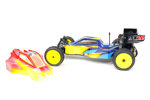
The Cab Forward body (TD402012) is designed to fit the DIMEC Chassis
To use either of the DIMEC chassis on your DEX210 model you will need the TD402012 DEX210 CAB FORWARD BODY.
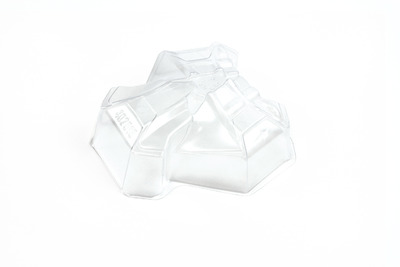
The TD402012 body uses the same cowling system as the original body, using the same TD402010 Cowling sets to allow the use of all the possible gearbox configurations on the DEX210 model with just one body.
Other changes required
Rear Suspension Arm Spacing
Depending on which anti-squat setting you are using it may be necessary to add shims to the rear hinge pins between the RR suspension hanger and the suspension arm.
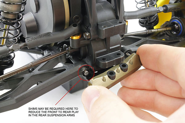
Shims may be required here, depending on the anti-squat used
With increased anti-squat you will need more shims to remove any front to rear movement in the suspension arms. It is important that you only add just enough shims to remove the front to rear movement from the suspension arms, please ensure that your suspension arms still drop freely under their own weight.
 Rear Suspension Hanger Screws
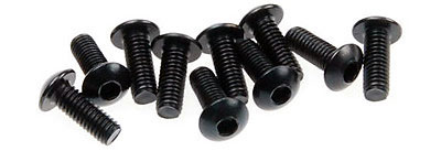
When swapping from the aluminium to the DIMEC chassis you will need to change the screws that hold on the RF and RR hangers for button head screws.
You will need to use 4 x M3x8mm Button Head screws (TD705002) in this area.
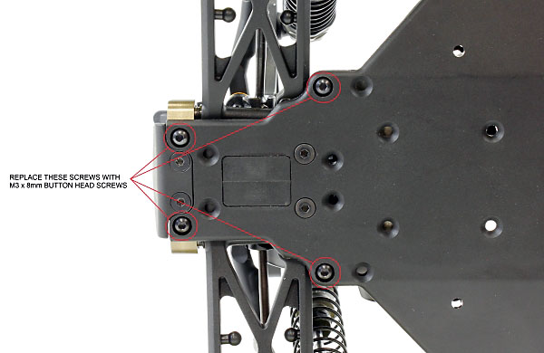
Swap these screws to button head screws
 Battery mounting
As the DIMEC chassis is longer than the original chassis there is the option to move the battery pack around in the buggy to adjust the weight distribution. Moving the battery forward will move the weight distribution forward and give more steering in general, especially into and through a corner. Moving the battery to the rear position will give more traction.
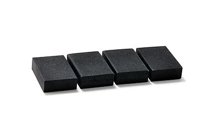
Team Durango offer a Foam Battery Spacer Set (TD390298) that can be used for spacing the battery packs. The foam spacers can be cut with a hobby knife (please take care when doing this!) to different thicknesses to allow for different battery sizes and for the battery to be placed more to the back or the front of the model to adjust the weight distribution and the handling of the buggy.
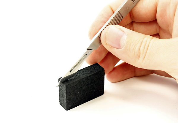
Cut the foam battery spacer to suit your battery pack
We recommend fixing the foam pad in front of the battery to the chassis with some double sided tape to ensure that it stays in place when you are running the buggy.
Rear Motor Layout
In rear motor layout you should use the second pair of holes back from the servo for the front battery stop. No battery stop is required for the rear of the battery. You should use a foam pad to take up the excess space, this foam pad can be placed either in front or behind the battery, allowing you to move the weight distribution.
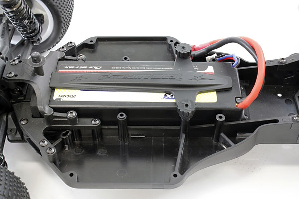
Batteries in the forward position, Rear Motor configuration
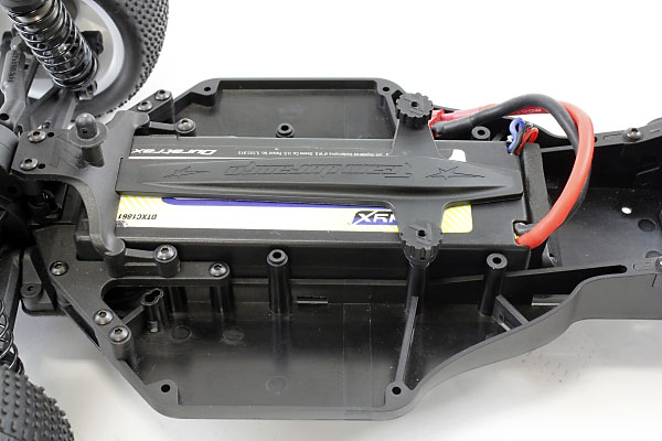
Batteries in the rear position, Rear Motor configuration
Mid Motor Layout
In the mid motor layout you should use the holes next to the servo for the front battery mount. The battery should be supported at the back of the model by using a foam pad between the battery and the motor.
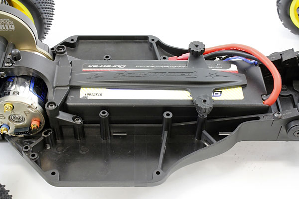
Batteries in the forward position, Mid Motor configuration
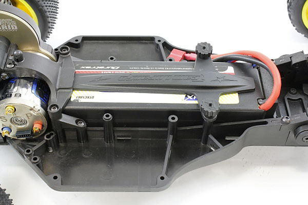
Batteries in the rear position, Mid Motor configuration
With the batteries in the rear position in mid motor layout you should always have some foam spacer between the battery pack and the motor to absorb any load, vibration or heat.

