Chapter 1 - Viewing of the first RC10 prototype
Going though some boxes tonight and found these parts. This is an early Team Associated RC10 prototype car tested and raced by Gil Losi Jr. I have a few of the old original prototype parts. Looks like I need to clean it up. Get it all back together and restore it. I don’t think this car has ever been photographed.
We built three cars originally. One for Jay Halsey, one for Gil Losi Jr. and one for AE factory testing. This will be quite a project. Time to find the missing pieces.

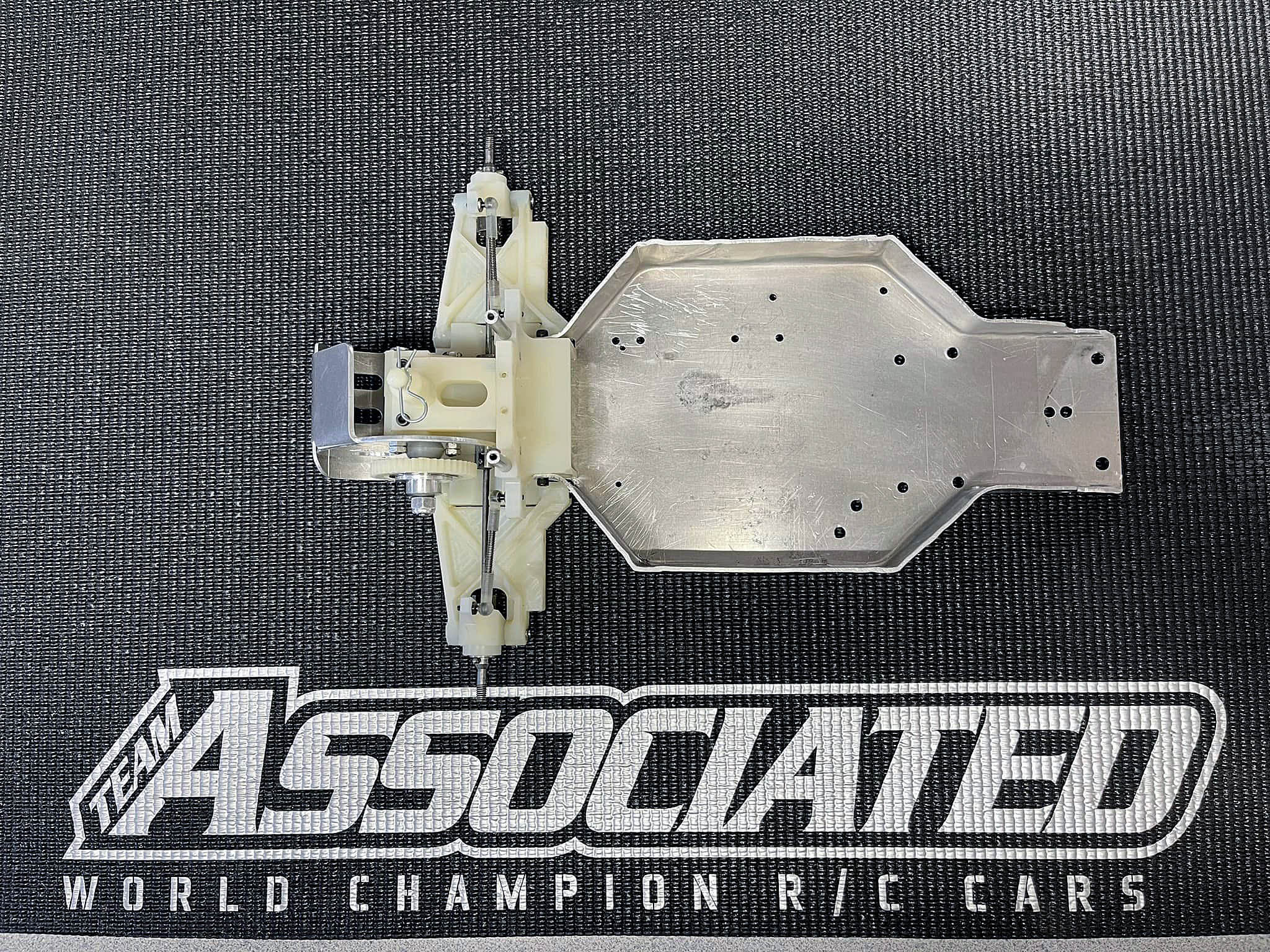
Chapter 2 - RC10 original Prototype Chassis.
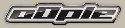
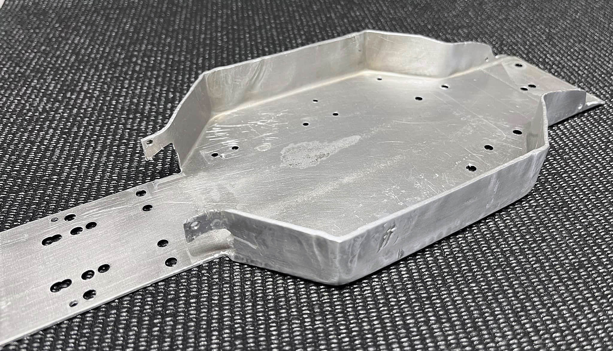
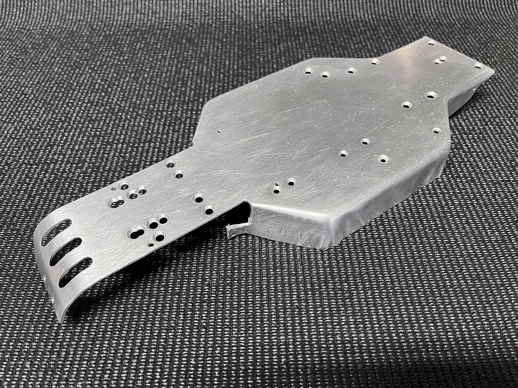
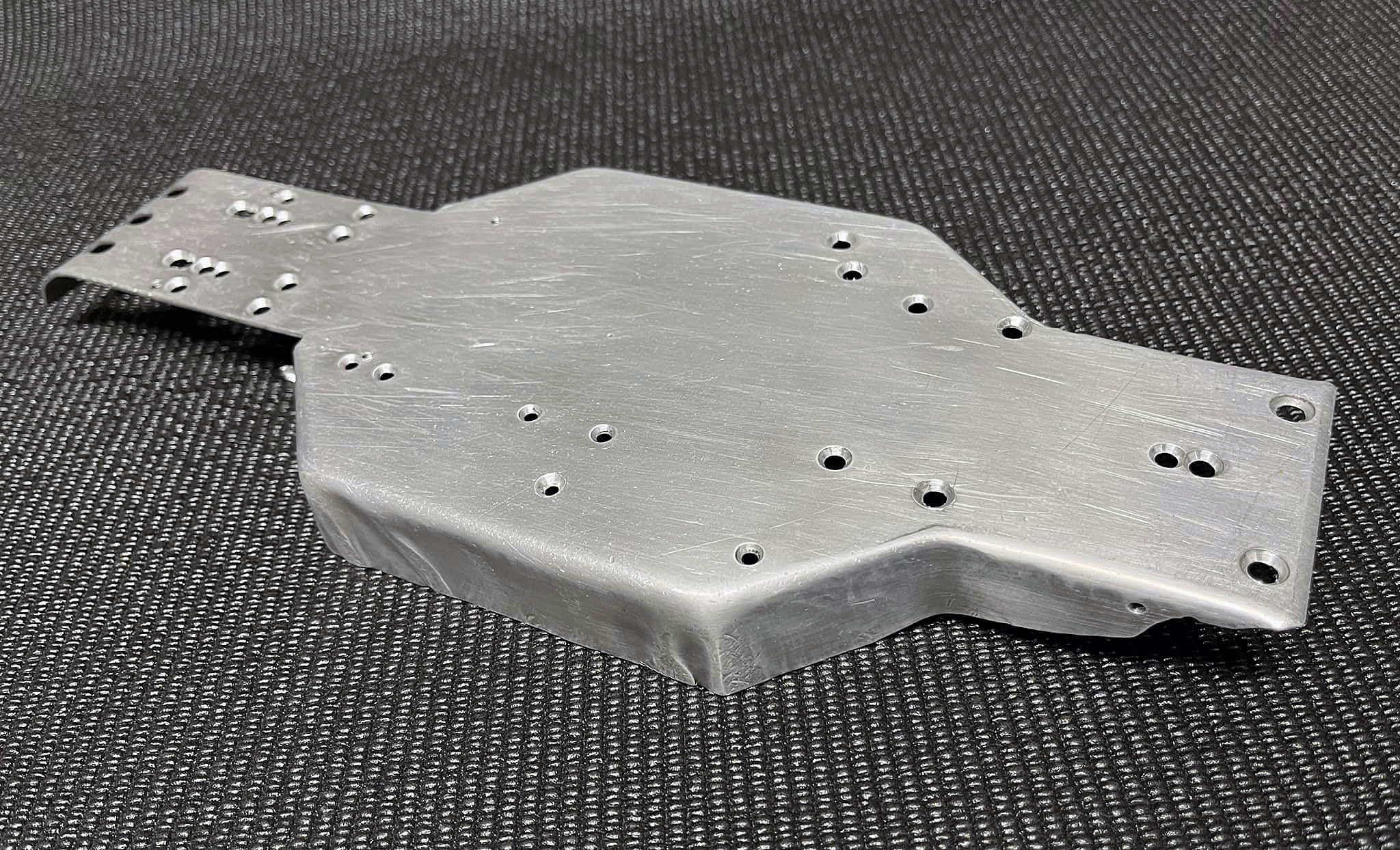
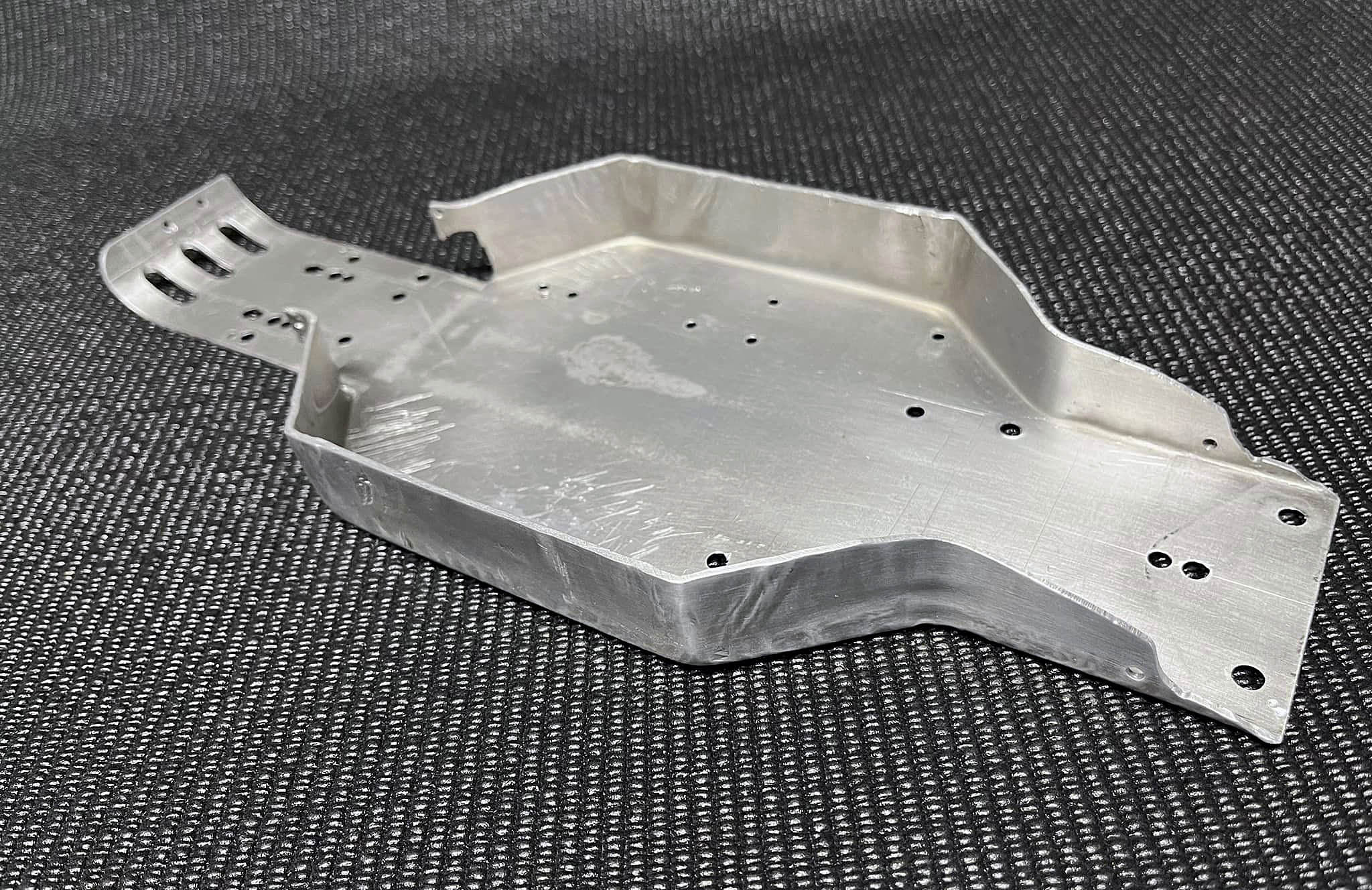
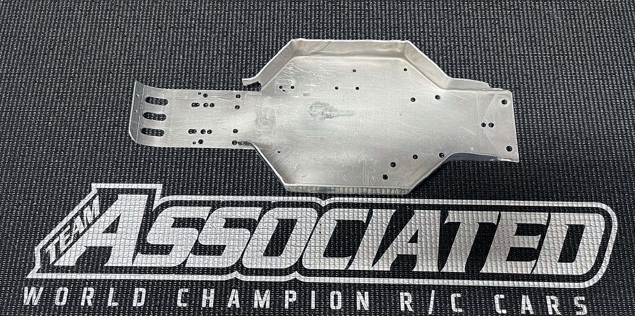
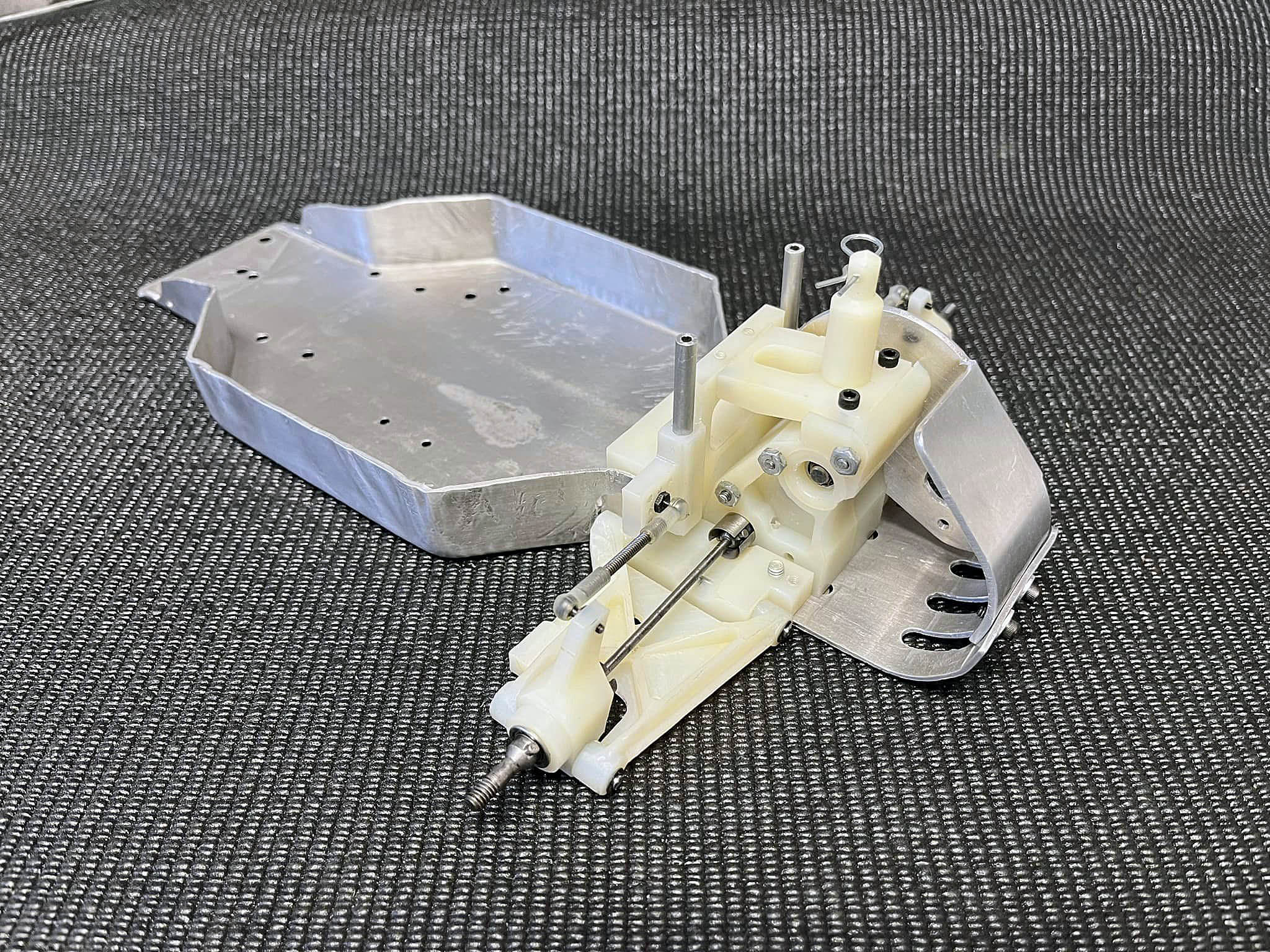
I got the chassis cleaned up a bit. This was one of the first RC10 chassis made and used for testing. Not too pretty and never photographed that I can remember. You can see how the sides show the wrinkles in the aluminum.
This started out as a flat piece of 6061-zero condition aluminum. Then formed around a 1 inch thick aluminum pattern. Using a rubber and brass mallet, hitting, pounding the sheet around the pattern. As the sides formed, the aluminum would gather to form the wrinkles that you see. In mass production these wrinkles aren’t seen. Mass production uses a huge hydraulic press to form the chassis. I assure you I got better forming these the more I made. The chassis was then heat treated and aged to get the full hardness needed.
This was the beginning of the RC10. From here we could make various front and rear arm mounts, suspension arms, front kickups, etc. to test with. Gil Losi Jr. and Jay Halsey were Team Associated test drivers at the time.
Roger Curtis was the brain behind the design. Me, Curtis Husting was the one making all the prototype parts. All hand made using manual lathes, mills and such.
My father Gene Husting, designed the wheels and managed test sessions and driving as well. This car was a team effort.
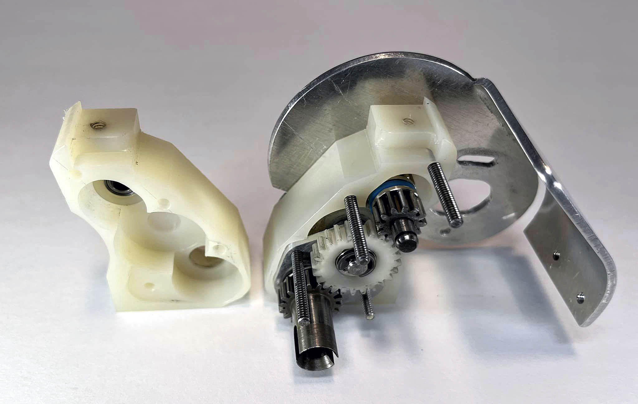
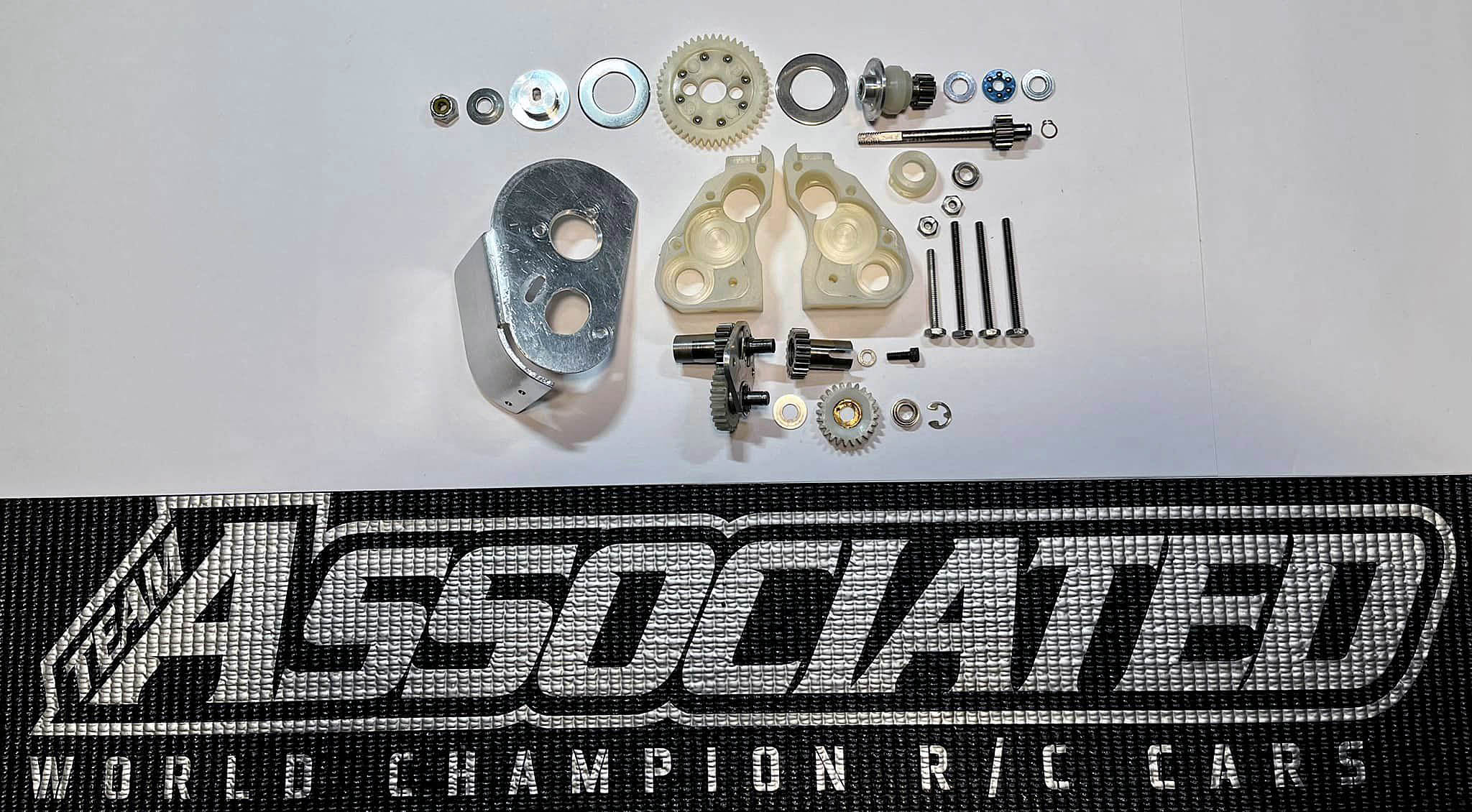
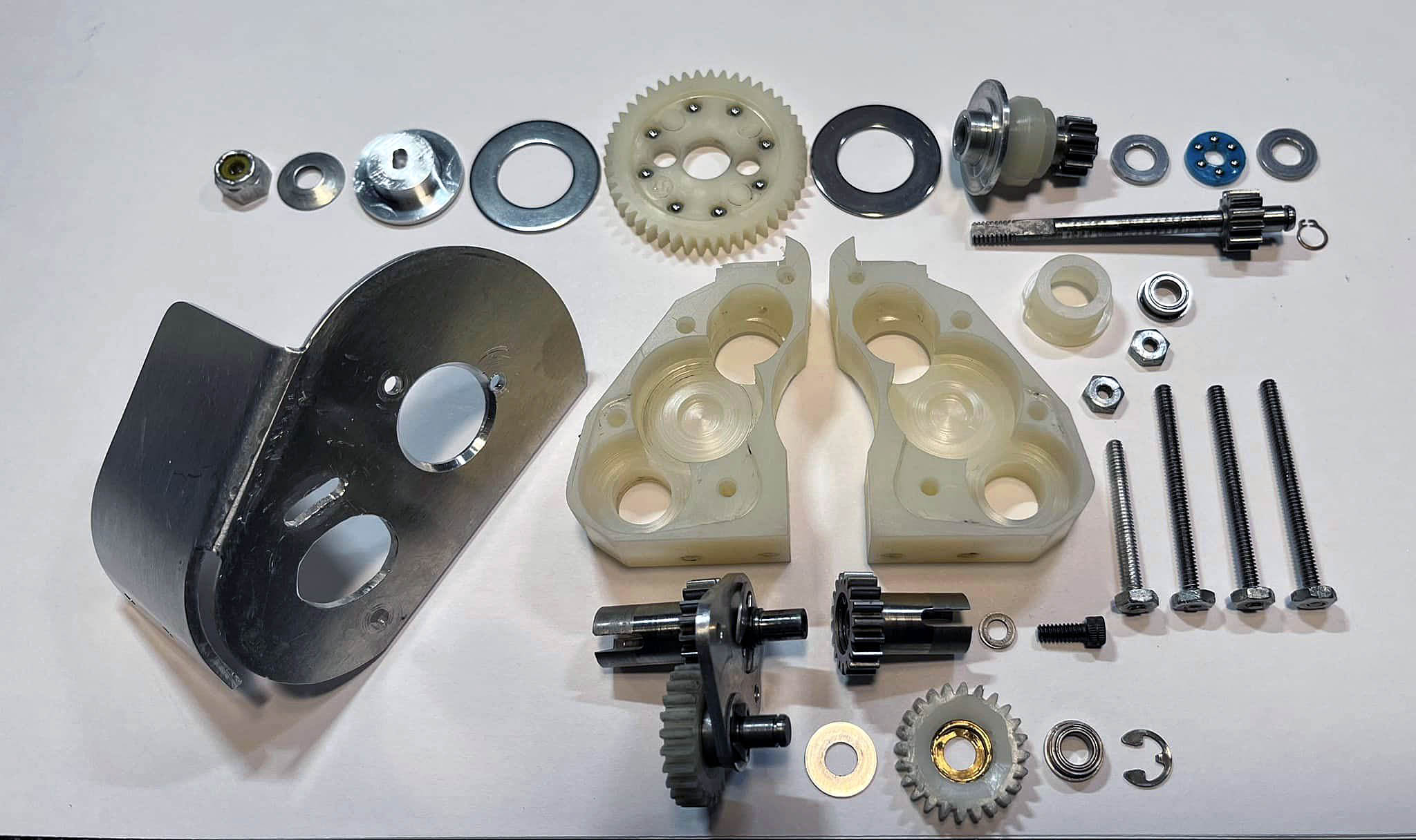
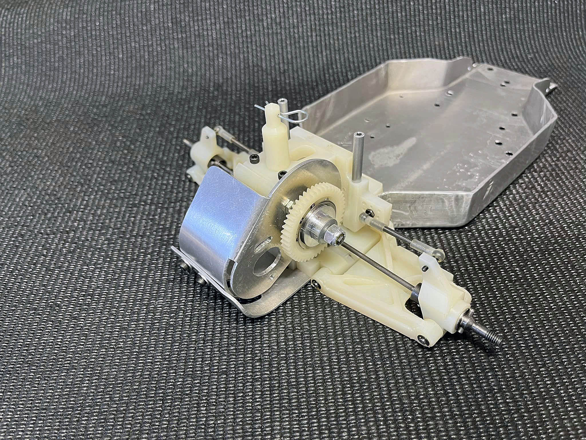
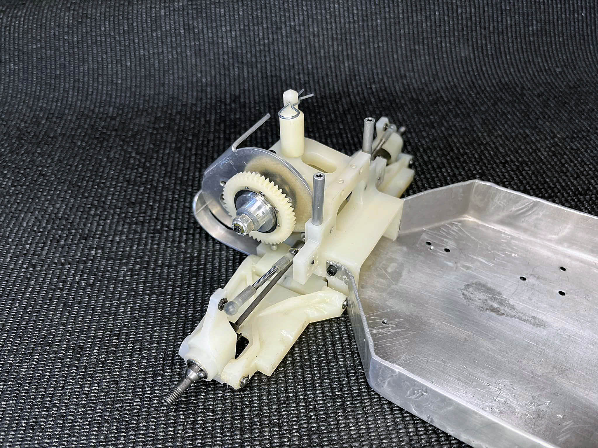
Chapter 3 - Transmission
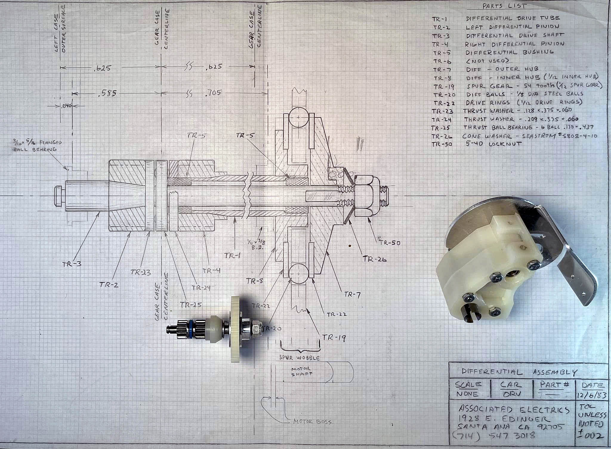
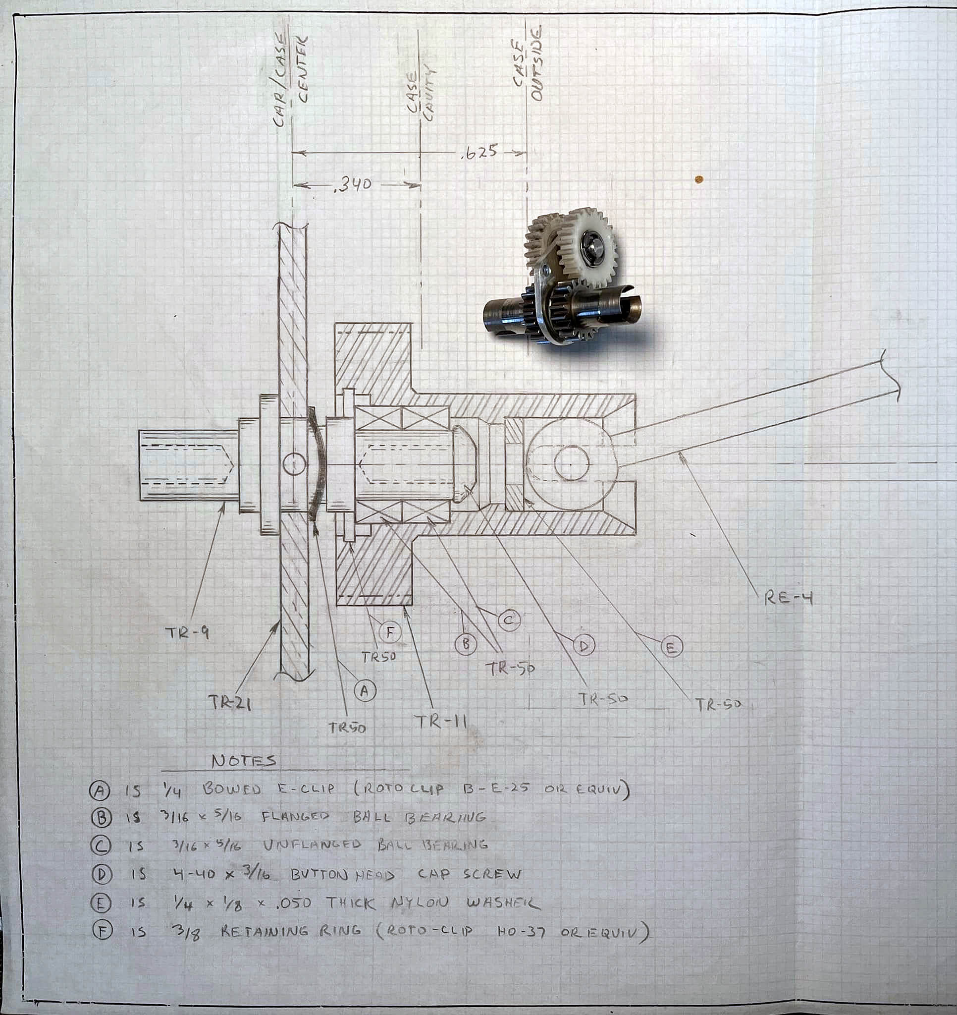
This is one of the original 6 gear RC10 prototype transmissions. Check the date on the drawing 12/6/83. That’s about 40 years ago. Roger would always make an assembly drawing to better visualize the concept.
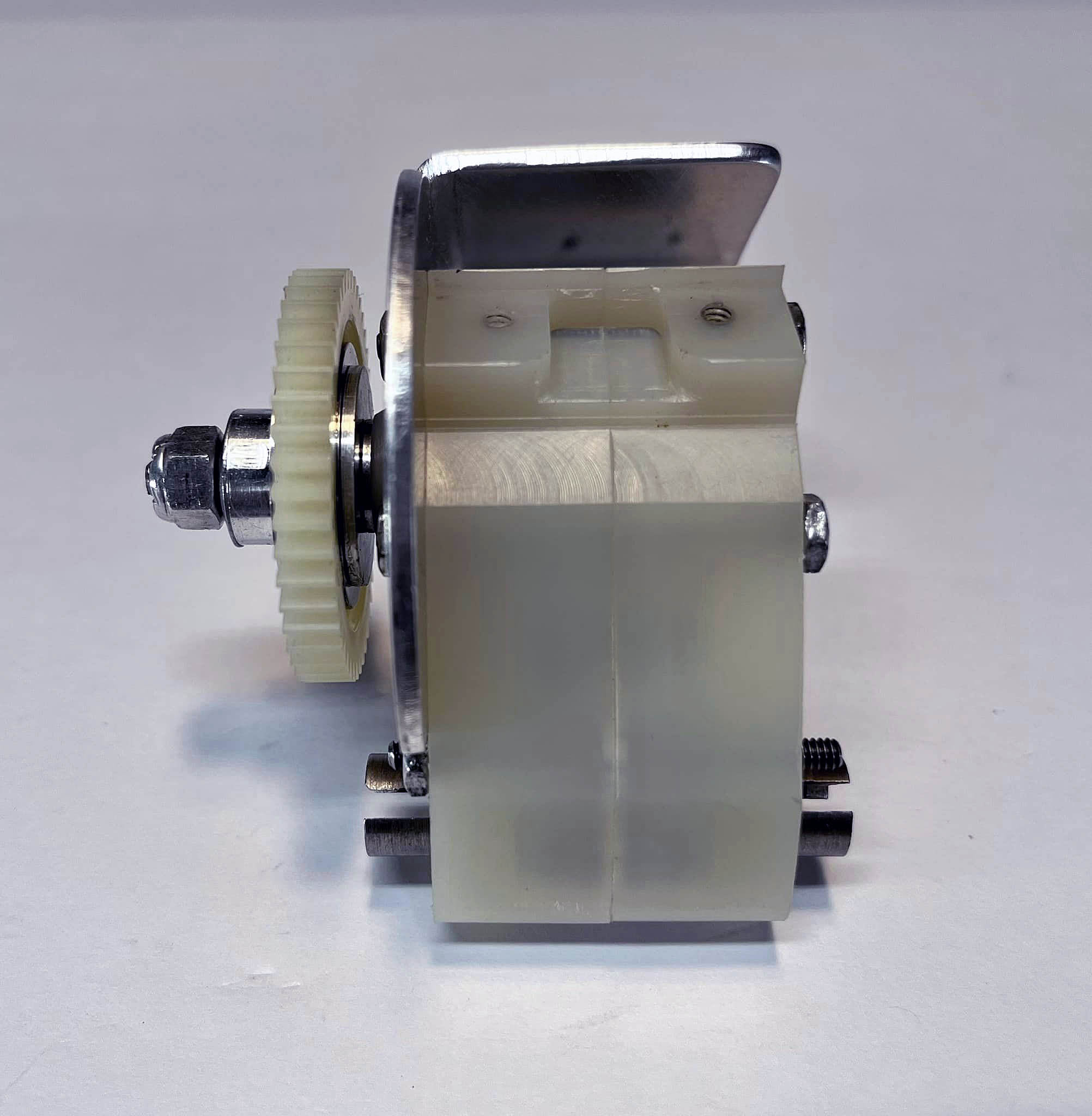
Looking at the Top Shaft Diff assembly, you can see there is no Slipper Spring. The first iteration had a Belleville Cone type spring and large Diff Nut. This was similar to what we were using at the time for 1/12 on-road car Ball Diffs. Future versions we changed to a spring that was used for production. If you look close on the drawing, Roger had penciled in a spring sketch.
Looking at the Diff Shaft, you can see it had a larger diameter (.140”) than what was used in mass production (.125”). Many of the parts changed along the way with slight changes and more prototypes.
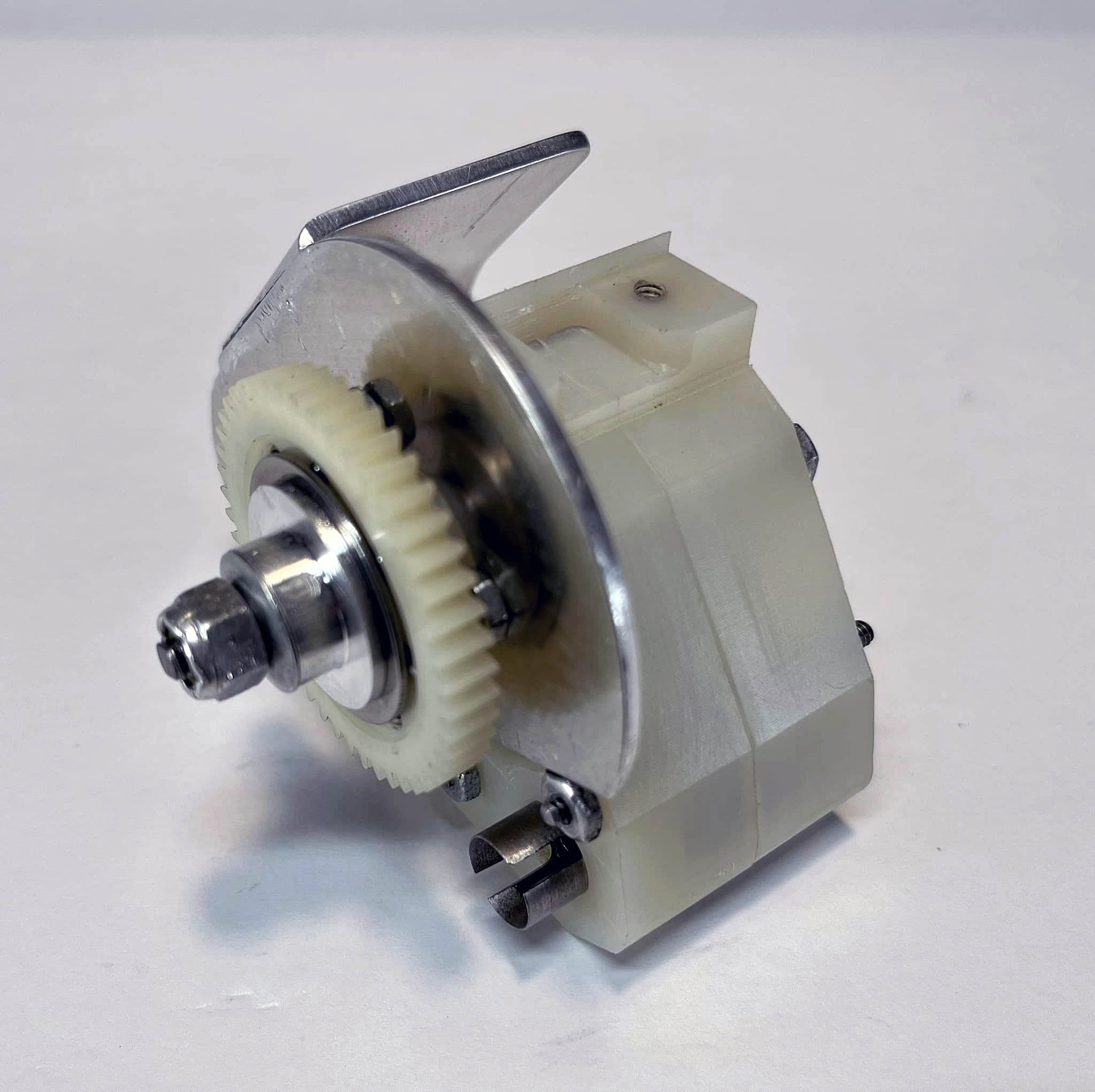
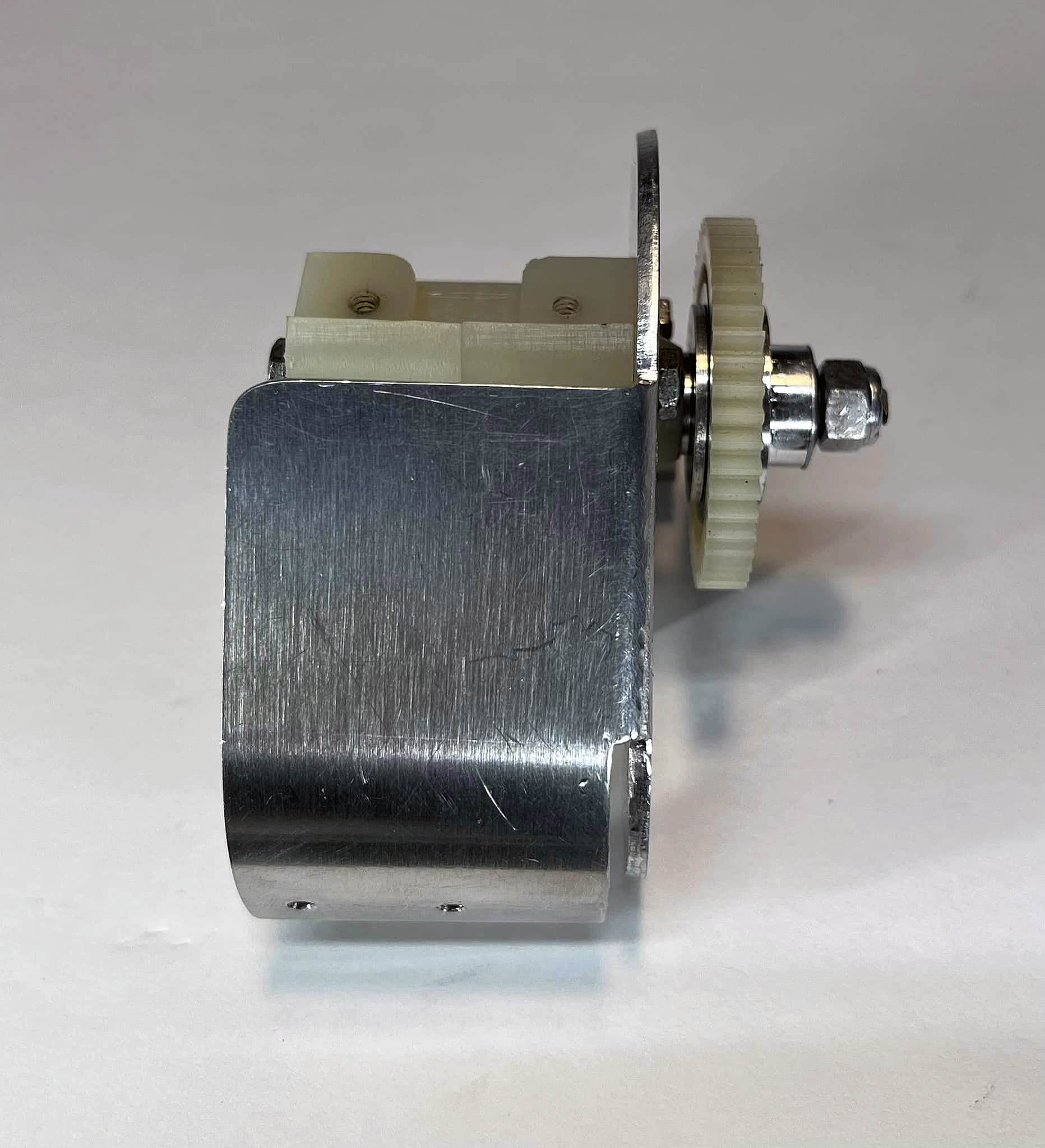
Looking at the Spine Plate assembly again, Roger drawing an assembly sketch to visualize with the Dogbone, you can see the Steel Outdrive Gears were smaller (18t) and the plastic gears were bigger (24t). This was changed later to get a better overall transmission gear ratio. None of these parts are molded. Everything was hand machined.
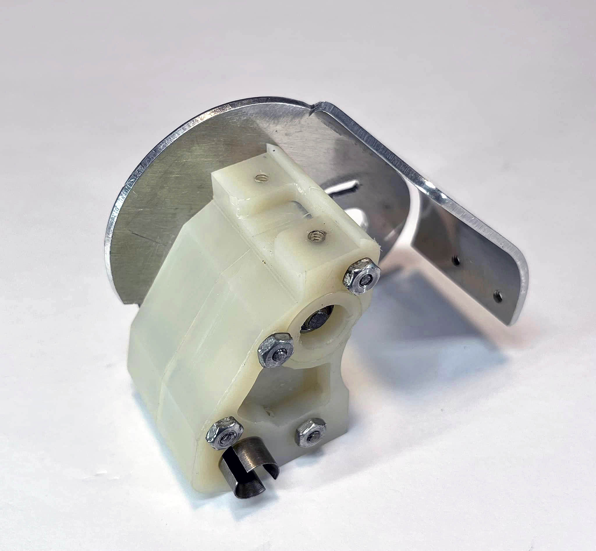
The Transmission Case looks very different from production.
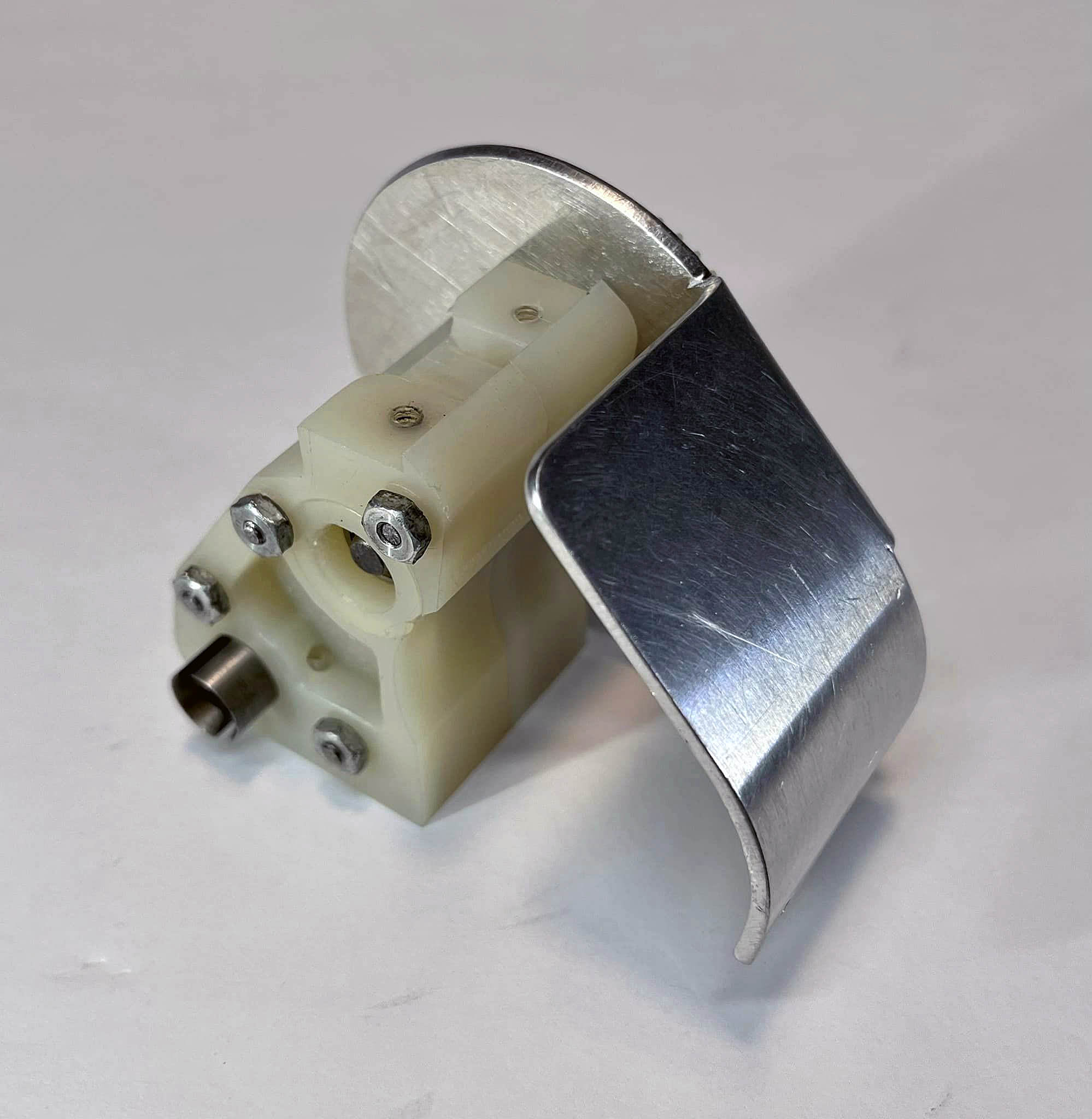
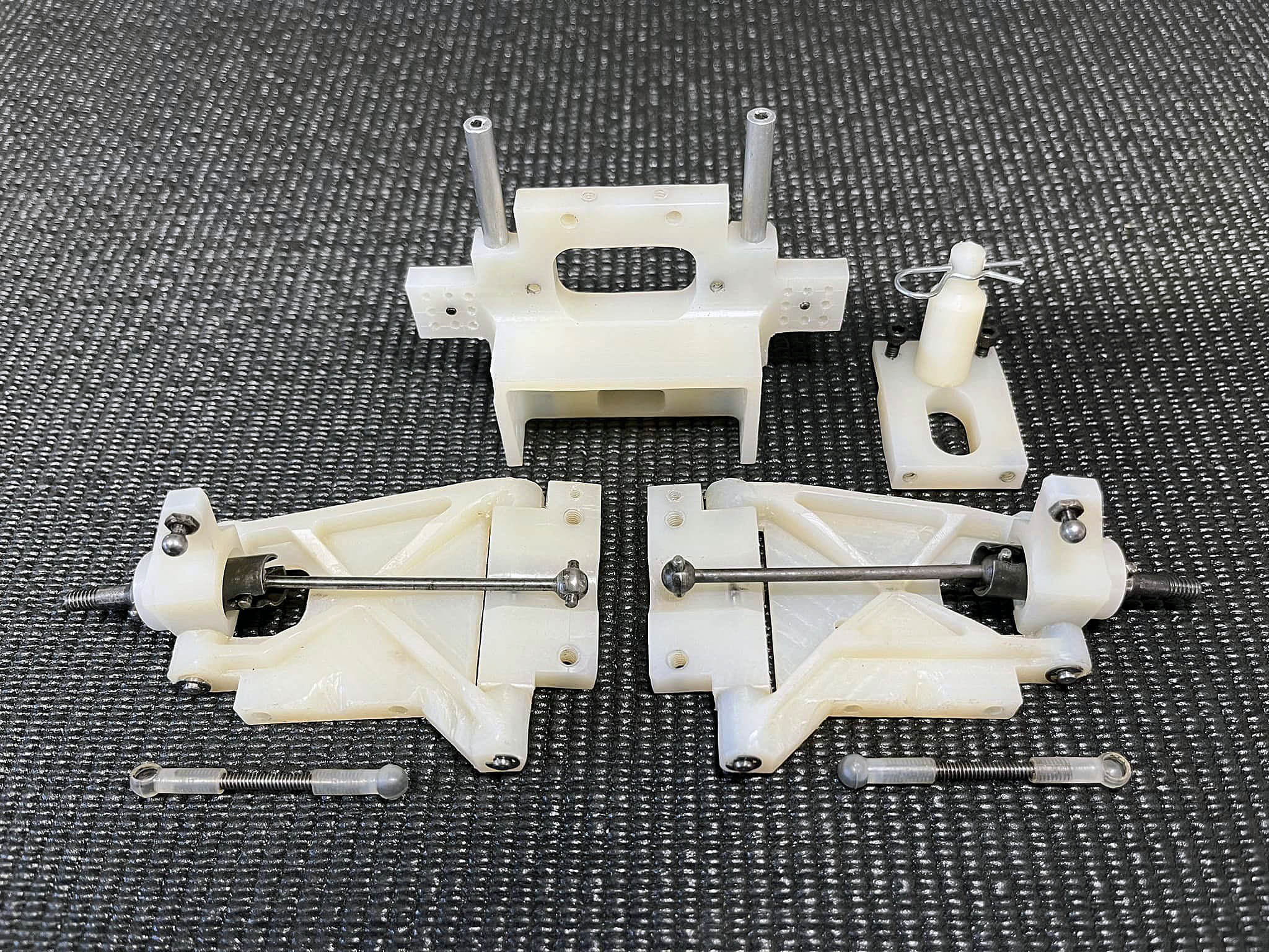
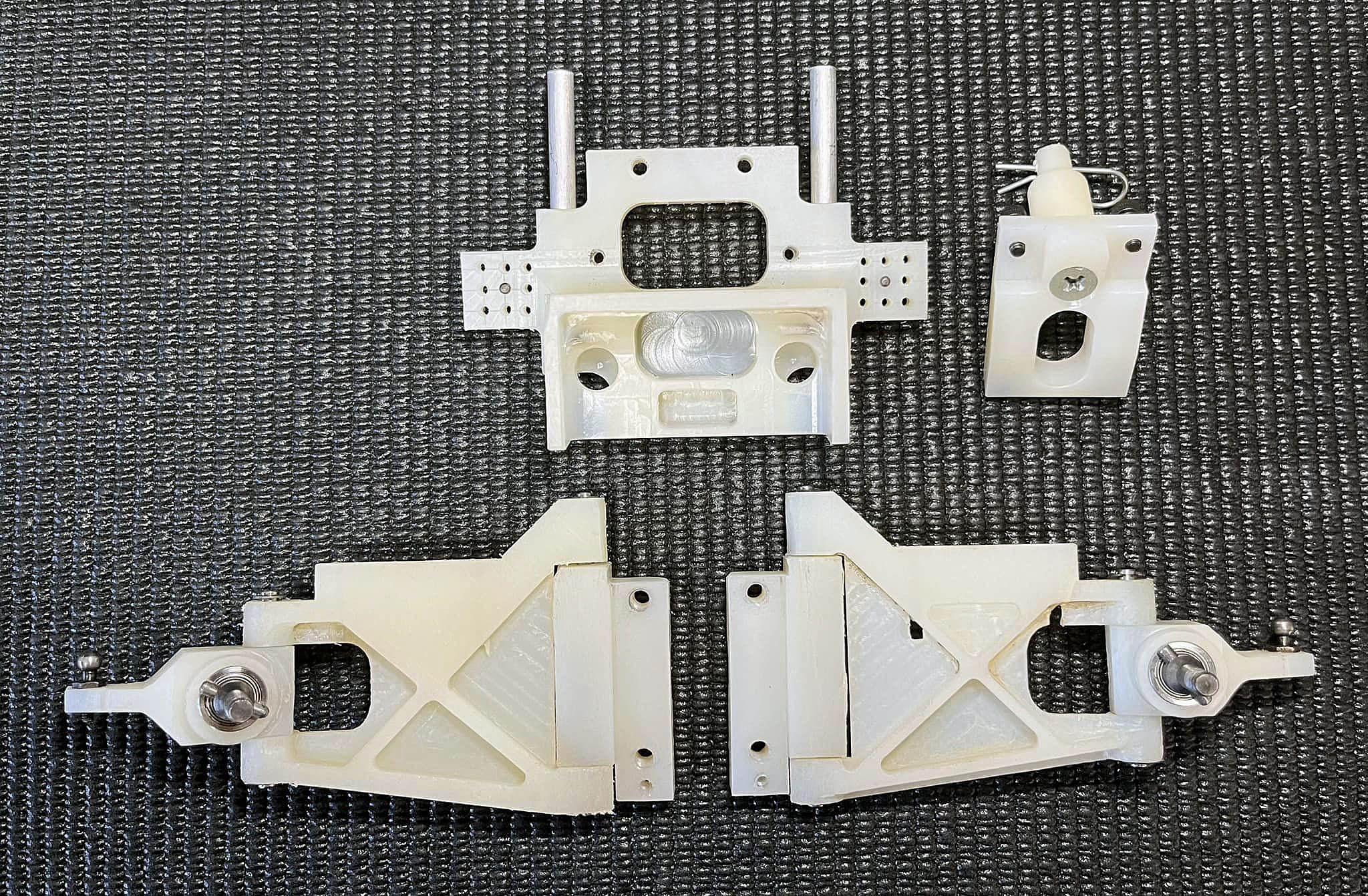
Chapter 4 - Rear Suspension
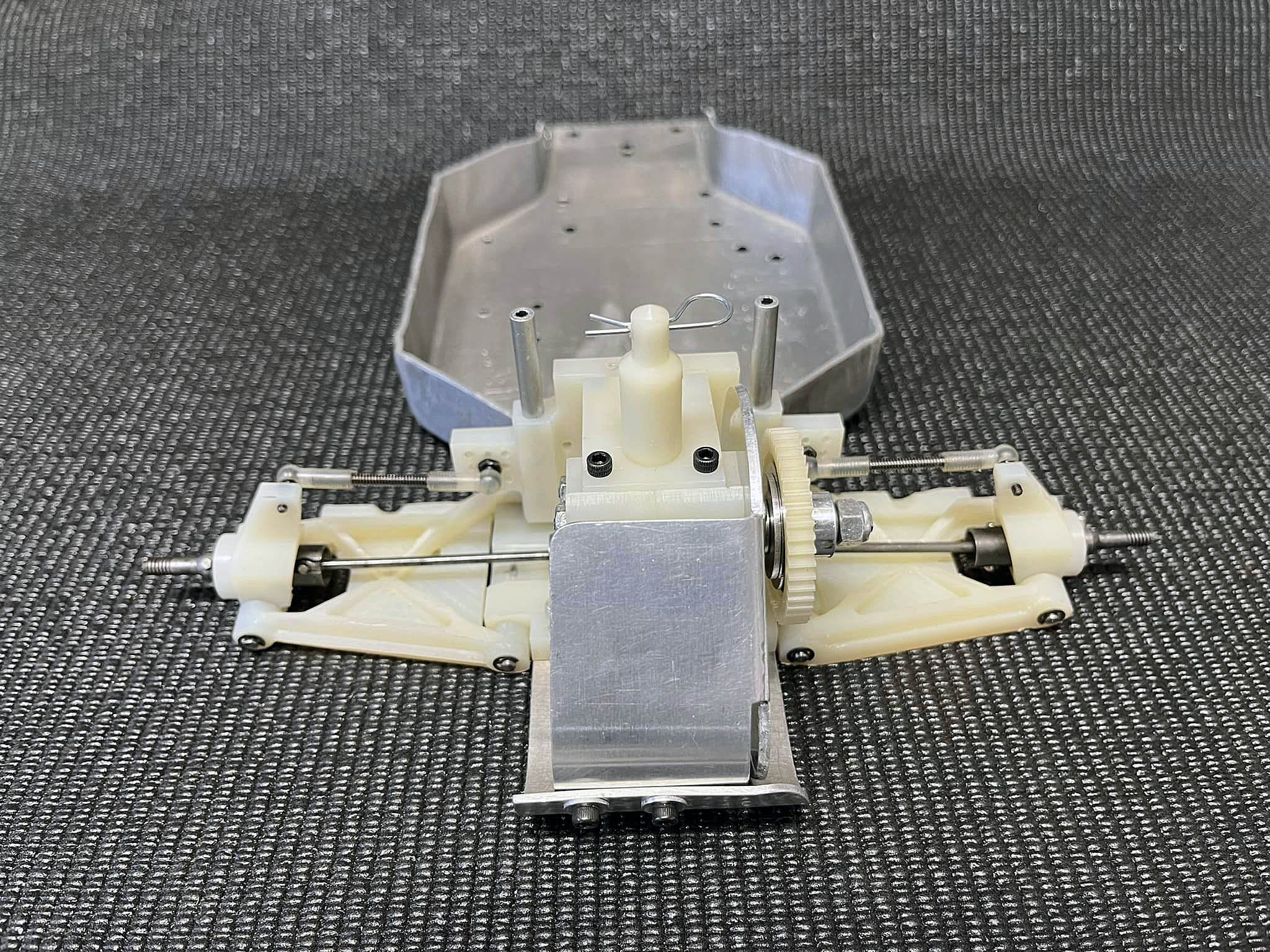
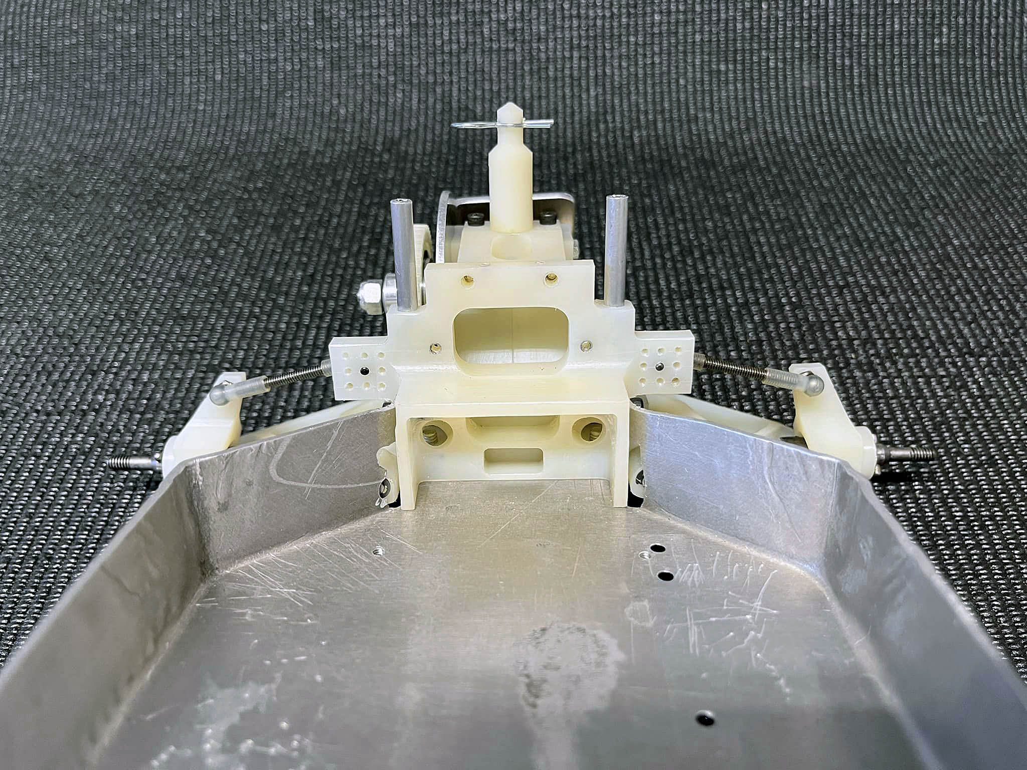
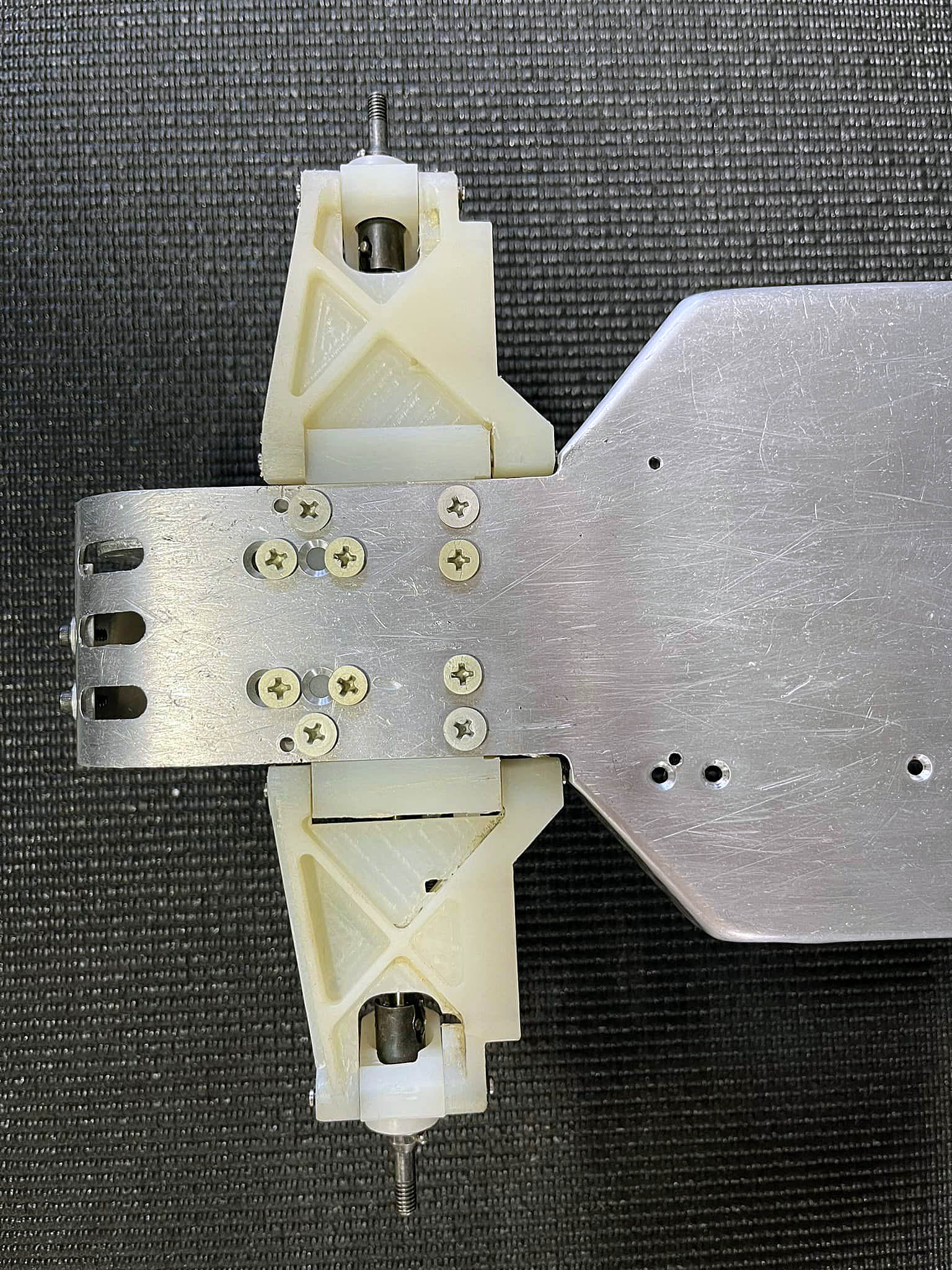
Here are some shots of the Original RC10 Prototype rear suspension. We used DuBro Ball Cups and Pivot Balls.
If you look close on the Arm Mount you can see an additional 4-40 size hole. The hinge pins were at zero degrees with no toe-in. If you took out the back 8-32 screws and put in the 4-40 screws, this would add 1.5 degree toe-in on each side. This was a quick and easy way to test.
The Top Brace looks quite a bit different than final production.
Next step will be the front end.


|