|
- Team Associated RC10B6: Purpose Built 2WD Buggy -
In the past, drivers had to settle for the single version of a 2WD buggy that a manufacturer offered. Depending on the track surface and condition, drivers had to make various adjustments to the car and hope for the best. Whether you were racing on high grip clay, carpet or old school loose dirt, you ran the same car.
Eventually, manufacturers started offering mid-motor designs, in addition to the traditional rear motor design. The two versions gave drivers more options. The general consensus is that mid-motor cars are better for carpet/turf/high grip tracks, which are generally more popular in Europe and the UK. Rear motor cars are supposed to be better for loose dirt/mid to low grip tracks.

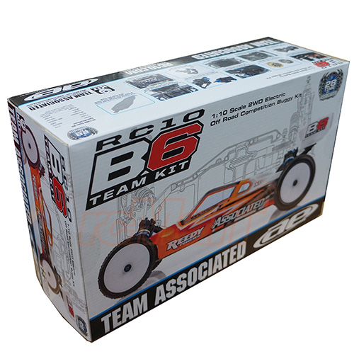
Here is the new Team Associated RC10B6. Image from Associated’s website.
Then came the Team Associated RC10B6 and RC10B6D and suddenly the game had changed. For the first time, we now have two different, purpose built cars. According to Associated’s website, it is a divide and conquer strategy. The RC10B6 is intended to be raced on carpet/turf/high grip tracks. The B6 features a mid-motor design with a new three gear “laydown” transmission. It comes with a gear differential. The B6 also features “gull-wing” front suspension arms and shock towers. Additionally, the B6 gives you the ability to install the rear shocks on the front or rear of the suspension arms for even more tuning options.
The RC10B6D is the choice for use on loose dirt/mid to low grip tracks. Hence the D in RC10B6D. It comes with a 3 gear stand up transmission. There is also a 4 gear optional transmission for use on loose tracks. Both the 3 gear and the optional 4 gear transmissions come with a ball differential. The B6D has straight front suspension arms instead of the gull-wing arms like the B6. Additionally, the rear shocks can only be attached to the rear of the arm.
Please keep in mind that the arms, shock towers and transmissions, among other parts, are interchangeable between the RC10B6 and the RC10B6D. The B6D can be converted to the laydown transmission for the princely sum of $27.20. That’s a pretty affordable option as well.
You may wonder what the main differences are between the RC10B5M and the B6. Here are the highlights:
| RC10B5M Team Kit |
RC10B6 Team Kit |
Comments |
| 3 gear stand up transmission with ball diff |
3 gear laydown transmission with gear diff (optional ball diff available) |
This allows greater versatility and tuning options. |
| 3-hole plastic rear hub inserts |
5-hole aluminum rear hub inserts |
All hub geometries have been moved to just the one insert on the B6, rather than using two on the B5M. |
| Plastic C plate and 2-hole plastic ball stud mount |
Aluminum C plate and 3-hole ball stud mount |
The pills in the inserts also allow for much greater adjustability with toe and anti-squat.
|
| Non-adjustable battery hold down strap |
Adjustable battery hold down strap |
This allows for weight bias, as well as height adjustability for those running low CG battery packs. |
| Traditional bell crank |
Reverse bell crank |
Allows for more room for servo placement. |
| Single size spring cup |
2 sizes of spring cups |
Both cars had this, but now there are two lengths that will be used depending on configuration, whereas with the B5, only one really was used. |
| 1 size shock eyelet |
2 different size shock eyelets |
This offers greater tuning options. |
| Plastic shock towers |
Carbon fiber shock towers |
Carbon fiber towers offer more rigidity and strength. Plastic is flexible which results in slightly less consistent geometry. |
| Open ball cup design |
Closed ball cup design |
Helps to keep dirt off the ball stud. Improved smoothness of operation. |
| Rear shocks mounted to rear of suspension arm |
Shocks can be mounted on front or back of rear suspension arm. |
This allows another option for track tuning. |
Features
- Turf/Carpet/Clay configuration
- 3-gear laydown Stealth(TM) transmission: lower CG and reduced polar moment
- Gear differential: more corner speed and forward acceleration
- Gull-wing front arms with wider shock tower: lower CG and increased on-power steering
- Ability to mount shocks on front or rear of rear arms
- Hard anodized aluminum pocketed chassis included. Optional weights (not included) allow weight bias tuning.
- Reverse bell-crank steering rack design allows more room for electronics
- Repositioned A plate provides maximum front end clearance
- One-piece steering blocks with bolt on Ackermann plate
- Lightweight and durable aluminum C plate and aluminum ball stud mount
- Updated ball cups and turnbuckles for precise adjustments and durability
- Adjustable battery hold-down strap allows weight bias tuning
- Aluminum front axle and rear hexes for less rotating mass and long-lasting durability
- V2 12mm “Big Bore” threaded aluminum shocks with 3mm TiN coated shafts and low friction x-rings for improved smoothness
- Factory Team Aluminum Shock Bushings provide stable shock mounts
- Heavy-duty rear axle for added strength
- Factory Team upgraded ball bearings
- Team Associated clear body and screw-mounted wing by JConcepts(TM)
| SPECIFICATIONS |
|
| Terrain: |
Off-Road |
|
| Body Style: |
Buggy |
|
| Scale Size: |
1:10 Scale |
|
| Assembly Level: |
Kit* |
|
| Length: |
varies |
|
| Width: |
varies |
|
| Wheelbase: |
280mm (11.02in) |
|
| Weight: |
varies |
|
| Drive: |
2WD |
|
Things needed to complete the build
- 1:10 scale 540-size electric motor
- 1:10 scale electronic speed control
- 7.4V LiPo battery (saddle pack, shorty pack, or square pack)
- LiPo capable battery charger
- 2-channel surface transmitter
- 2-channel receiver
- Steering servo
- Pinion gear (48 pitch)
- Polycarbonate-specific spray paint for body
- 1:10 scale buggy wheels
- 1:10 scale buggy tires
- Glue for tires and wheels
Other Helpful Items
- Silicone Shock Fluid (Refer to catalog for complete listings)
- Body Scissors (AE Part # 1737)
- Reamer / Hole Punch
- Shock Pliers (#1675)
- Wire Cutters
- FT Hex/Nut Wrenches (AE Part # 1519)
- Needle Nose Pliers
- Multi Tool (AE Part #7494)
- Hobby Knife
- Soldering Iron
- Calipers or a Precision Ruler
- Green Slime shock lube (AE Part # 1105)
Unboxing
The Team Associated RC10B6 arrived while I was at work. Like a kid that wakes up early on Christmas day, I couldn’t wait to get my hands on the box. Once I got home, I was greeted by the box, which featured a nice photo of the finished, painted car. On the sides of the box were descriptions of the features and specifications, as well as, some great pictures.
When opened the box, I found a lot of plastic bags! 26 bags give or take, plus the manual, Team Associated clear body and screw-mounted wing by JConcepts(with window masks) and other miscellaneous bits and pieces. There were also info sheets for other Associated vehicles, a decal sheet, an assortment of Allen wrenches, a box wrench and a turnbuckle wrench.
The bags were all clearly labeled with numbers that corresponded to the steps in the manual. Since RC10B6 comes as a kit, the manual is very important to the build process. Typically, Team Associated manuals are top notch. This one excellent.
The cover features the same picture as the cover of the box. Pages 2-4 gives and overview of the car, a 1:1 scale view of the hardware included in the kit, as well as, a table of contents. Pages 5 through 18 contain the step-by-step build instructions. The steps feature computer generated images of each part along with the necessary hardware.
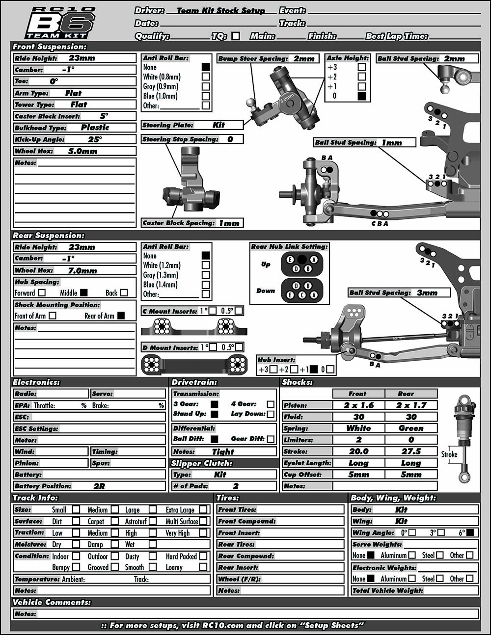
The rest of the pages consist of a section of awesome tuning tips that really explain what the various adjustments will do for the car and pages of exploded view diagrams of the various major assemblies of the car, with part numbers. There are a few pages of optional parts along with a stock setup sheet along and a blank one.
During the build process, I came across some inconsistencies in the manual between what the text of the steps called for vs what some of the pictures called for. I will cover these during the build section of this article. I contacted Shawn Ireland, Vice President of Sales and Marketing at Team Associated, to discuss the inconsistencies. Shawn assured me that they were aware of the issues and were in the process of sending new graphics to the printer to be used in the next print run of the manual. In addition, you can find an updated version online. The updated manual is still a work in progress.
You will also find a blank, editable PDF version of the setup sheet, along with a number of customized setup sheets by some of AE’s top drivers for different track conditions.The Team Associated website is an excellent resource. Another great resource is a Facebook group called RC10B6 Nation. The group bills itself as the #1 Facebook resource for generation 5 and 6 vehicles. I would have to agree. I found a lot of info by just reading the posts. Additionally, I asked a few questions and got very helpful advice. I highly recommend checking it out if you get a have a B5 or a B6. |
|
|
The Build
The Team Associated RC10B6 was, by far, the easiest build I’ve ever done. I don’t mean it was easy because it was a simple car to build. That is surely not the case here. The B6 is a complicated vehicle with a lot of options, including different inserts, washers, link placements, shock eyelet and spring cup sizes. It was easy because the fit and finish of the parts and hardware were amazing. Having all the parts in labeled bags and well organized made it easy as well. Obviously, I can’t cover every step of the build. I will touch on any steps that were difficult or very important. I’ll also cover helpful hints, either as called out in the manual or ones I came up with myself. Finally, I will let you know when I come across the inconsistent info in the manual.
Before I start, I wanted to give you a few tips. I used 18 In x 72 In Nonslip Toolbox Solid Liner as a mat on which to work on my RC vehicles. I got a roll of it for $7.99 from Harbor Freight. It prevents hardware and other small objects from rolling off your bench. I cut it into two 36” sections. I keep one on my bench and one rolled up in my pit box for when I go racing.
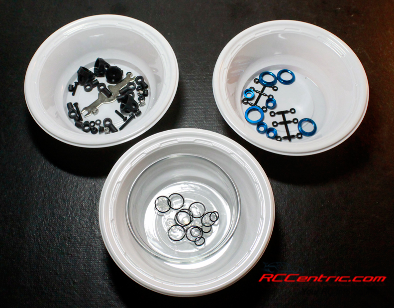
Plastic bowls are great for organizing the parts and hardware used for each step.
Do yourself a favor and pick up a bunch of disposable plastic bowls. They are great for keeping the parts organized once you open a bag. Just dump the contents of each bag into a new bowl as the step calls for it. They can also be good for dumping out old shock oil when you are rebuilding your shocks. In fact, I cut four holes into the bottom of a bowl and flipped it over. I now have a quick and dirty shock stand.
While Team Associated includes a bag with the tools needed to build the car (1.5mm and 2mm Allen wrenches, 12mm shock tool and a multi wrench for use on the different lock nuts on the kit, I strongly suggest getting some nut drivers and Allen wrenches with handles. The little Allen wrenches can be tough to work with for an entire build. Now, let’s get started.
The steps are broken down by bags. Bag 1 walks you through assembling the bell-crank steering rack. The biggest thing with this step is taking your time. Make sure you observe the orientation of the parts as you assemble them, or you’ll get yourself into trouble. Of particular note is the bell-crank brace. It has a small round offset on one side. Make sure you orient it so that the offset faces the bearings in the bell-cranks.
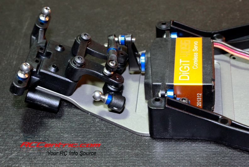
Steering assembly and servo are attached to the chassis.
Bags 2-4 cover a major portion of the RC10B6 front end. The first step is attaching the bell-crank steering assembly to the to the front bulkhead and onto the front of the chassis. The bulkhead has two settings for kick up angle: the recommended 25° angle and 30°, which are molded into the bottom of the part. Make sure the 25° arrow faces the front of the chassis when you attach it. Be careful when you attach the plastic side rails to the aluminum chassis. The flat head screws are very close in size. Four M3x10mm are used in the front of the chassis, while the remaining six M3x8mm screws are used for the rest of the side rails. The rest of the steps are pretty straight forward.
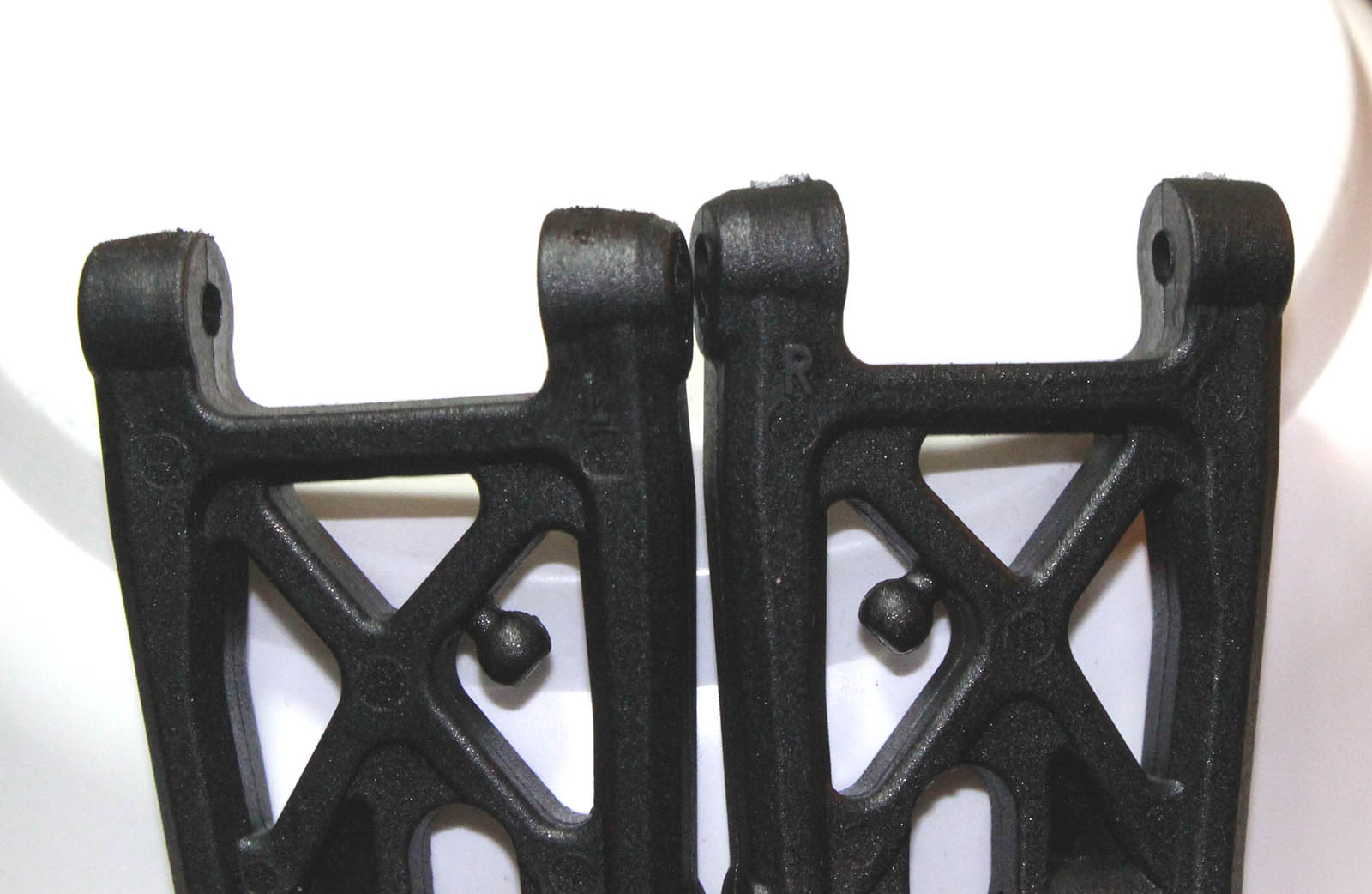
Use a hobby knife to carefully remove extra material from the suspension arms. The one on the right is before cleanup. The one on the left is after. I use a black Sharpie to blend the color.
When you are attaching the servo horn to the steering servo, you want to make sure the servo is in the neutral position. I had my ESC, receiver, battery and servo hooked up on my bench. I turned them on and set the steering trim on the transmitter to zero so that the servo horn could be attached in the neutral position. As you attach the servo horn to the servo, please tighten down the screw all the way. You don’t want it popping off during when you are testing out the car, as happened to me!
Bags 5-8 details the building of the left and right steering blocks and camber blocks. The caster block inserts allow you to set the amount of caster. Caster is the amount the kingpin leans toward the rear of the car at the top. Positive camber is when the kingpin leans back, while negative camber means the kingpin leans toward the front of the car. The B6 comes with three sets of inserts to adjust caster angle at the caster block: 0°, 2.5° and +5°. The total caster angle of the front end is the sum of the kick-up angle and the caster block angle. Standard total caster angle for the B6 is 30°, with 25° kick-up and +5° caster block angle. There is a helpful chart in the manual that shows you the various combinations.
Please make note of step 3 of this section. There is some confusion about the caster hat bushings. The picture shows them as the same size. However, the text says to use the 1 mm on the top and 2 mm on the bottom. Go with the text.
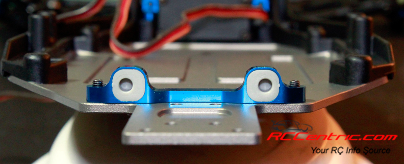
Aluminum C mount with inserts.
Bags 9-10 walk you through attaching the C mount and D mount, as well as, the rear suspension arms. This is an important section because this is where you set the rear toe-in and anti-squat. The C mount is aluminum and has a variety of plastic inserts to set it up as you desire. The manual recommends 2.5° toe-in and 1° anti-squat. Something that I found a bit confusing is the fact that the D mount, which holds the rear of the hinge pins in place, is molded plastic so there is no adjustment. However, if you were to look at the setup sheet in back, it shows the D mount with plastic inserts that allow you to make even more adjustments. I believe the manual should have mentioned in the step that there is an optional aluminum D mount with the adjustments. Just having it in the setup sheet without any explanation is a bit unclear.
I found another excellent resource that explains everything about camber, caster, toe-in, anti-squat, shocks, tire selection and anything else you can imagine; RC Handbook E-Book. According to the preface on the web page, “This material first appeared as a printed booklet by Scott Guyatt of Heavy’s Hobby Shop, Australia. It was written “to help local kids avoid all the pitfalls we didn’t manage to” over eleven years of racing off-road buggies…Associated came across the material and entered into an agreement with Scott to incorporate it into this site. Associated modified the pages of Scott’s web site to update it with today’s technology and to relate it directly to the concerns of Associated kit owners.”
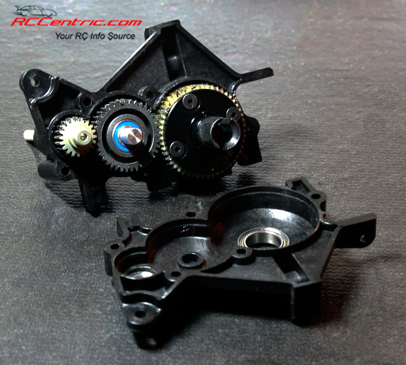
Bags 11-14 cover building the transmission and mounting it on the chassis. It is pretty straight forward. Make sure you put in enough of the diff fluid so that it covers the planetary gear cross pins. Too little and you’ll not have a smooth diff. Too much and it will probably leak. Don’t forget to add a drop of diff lube (not diff fluid) to the teeth of the diff gear, idler gear, and top shaft.
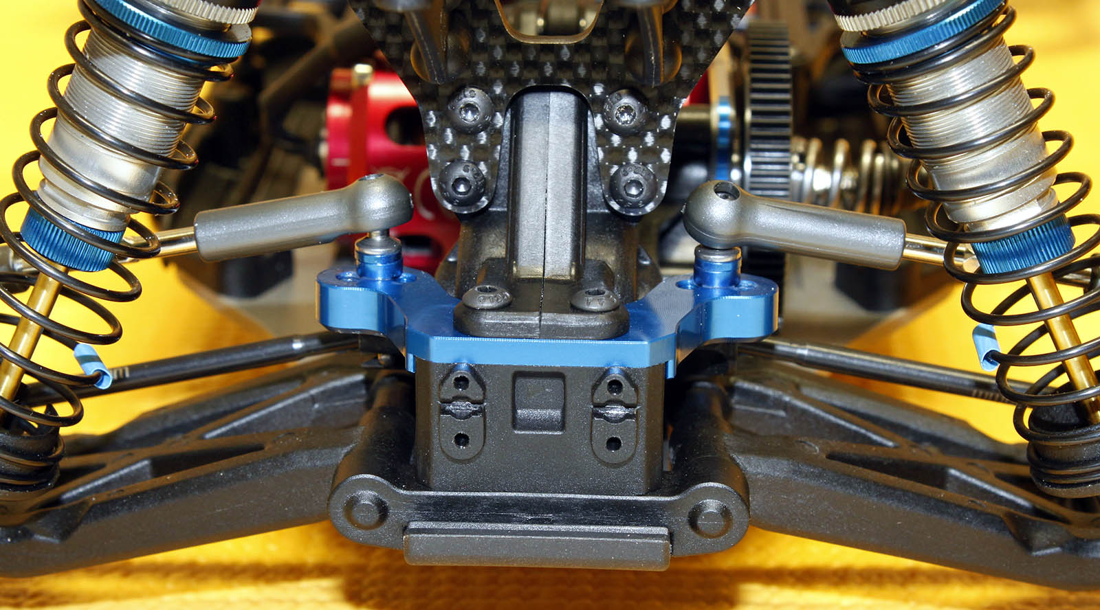
Rear ball stud mount is shown with the ball studs in the middle hole.
I want to point out step 8 of this section. It covers the assembly of the rear ball stud mount. The graphic in the manual shows the ball studs mounted in the outermost holes in the mount. However, in later pictures, they are shown using the center holes. The center hole is the correct hole to use for the stock configuration.

Aluminum rear hub link mount. The manual recommends using the center hole with the insert in the down position.
Bags 15-16 detail remaining steps in the building of the rear end of the RC10B6. Step 1 is the very important. Here, you will put together the rear hubs. The hub features a 5-hole rear hub link insert. They can be oriented with either three holes across the top (up position) or two holes across the top (down position). The recommended setting is with the insert in the down position and the ball stud in the center hole. There are also rear hub inserts that let you determine ride height. You have a choice of 0mm,1mm, 2mm and 3mm. The manual recommends you use the 3mm hub insert.
Bag 17 guides you through assembling the steering turnbuckles, front camber turnbuckles and rear camber turnbuckles. There are a few things to keep in mind that will make your life a lot easier. Each tie rod has a notch to one side of center. You should make sure the notch is to the left on all the rods. This indicates which side has a left hand thread. When you adjust the turnbuckles, you will know that if you turn it forward, it will have the same effect, no matter which turnbuckle you are adjusting. When you are threading the rods into the rod ends, please put a little black grease on the threads. It will allow them to thread more easily.
Step 3, the assembly of the rear camber links, instructs you to make the link 27mm long when you measure the exposed rod. This is incorrect. If you build them at 27mm, your rear end will have a ton of positive camber. I wound up adjusting it until the rear tires had -1° of camber. If you don’t have a camber gauge, I would highly recommend getting one right away. Team Associated makes a camber gauge, as do a number of other companies. As with the other inaccuracies, Team Associated is aware of them and will be correcting them in an updated manual.
Jumping ahead to bags 20-22, building the shocks. These went together very easily. Just pay close attention to the text and diagrams, so that you put all the correct washers, spacers, O-rings, etc., in the right order and location.
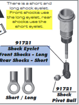
The yellow highlighted area is incorrect. The blue area is correct.
There is one issue that you have to watch out for. The RC10B6 comes with two different length shock eyelets: long and short. The text block calls for you to use the short eyelets on the front shocks and the long eyelets on the rear. However, the label text on the diagram says the opposite. The correct stock configuration is long on the front and short on the rear. This has already been updated in the online manual.
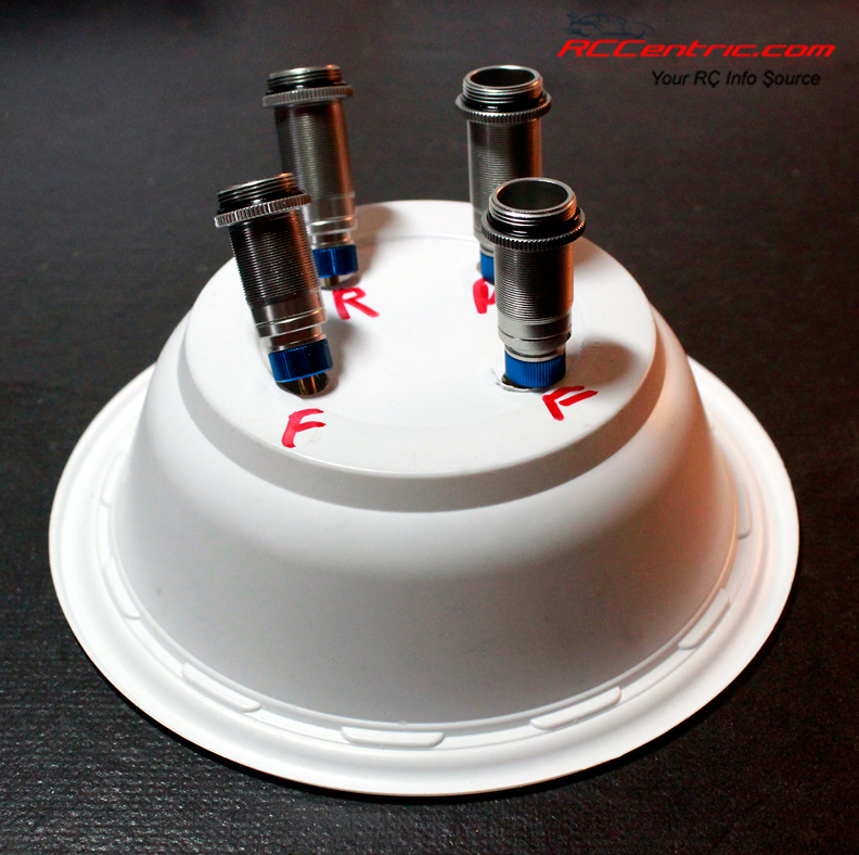
Home made shock holder. Holes were cut in the plastic bowl.
The instructions for filling and bleeding the shocks are very good. A key point, when bleeding the shocks, is that you should see some oil come out of the little hole in the top side of the cap when you compress the shock. If you don’t see any oil come out, you may not have put enough in. In that the case, open it up and put in more oil. Once you bleed the shock, with the shaft still compressed, thread the small set screw into the hole do seal it. I missed one myself and had a leaky shock.
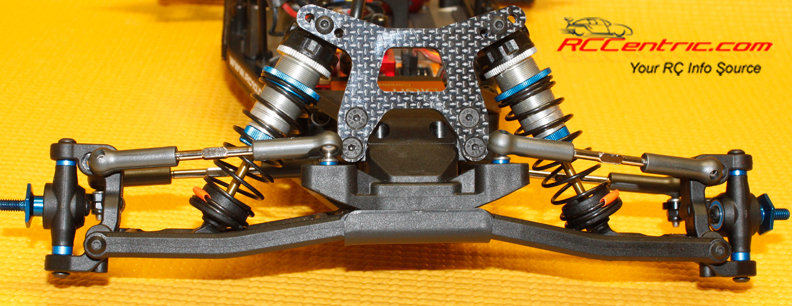
The front shocks use the middle hole on the shock mounts. The V2 12mm “Big Bore” threaded aluminum shocks are very smooth.
The final steps of bags 20-22 involve mounting the shocks to the car. For the front, I went with the recommended center holes in the shock towers. I also went with the outside holes on the front arms and inside hole on the rear arms. The B6 rear arms allow you to mount the shocks on the front or back of the rear arms. Stock setup is to mount them on the front. The setup tips in the back of the manual gives a good breakdown of when to mount them on the back of the arms vs the front. Essentially, mounting the shocks on the front of the arm moves the rear weight bias forward. This causes the car to turn more quickly and also steer more on-power. Typically, this is used on high grip tracks, which will keep the car steering while getting on the throttle. Mounting the shocks on the rear of the arm shifts some of the weight bias to the rear of the car. This keeps the rear end planted while increases the steering radius. This typically makes the RC10B6 easier to drive and will provide more rear traction.
The rest of the car goes together without any issues. One thing to watch out for is correctly trimming the rear of the body. There are a three options for the rear of the body. Use trim line A if you are running the laydown transmission and mount the rear shocks on the back of the rear arms. Use trim line B with the shocks on the front of the rear arms. Trim line C is used if you are running the standup transmission. Since I mounted mine on the rear of the arms, I used line A.
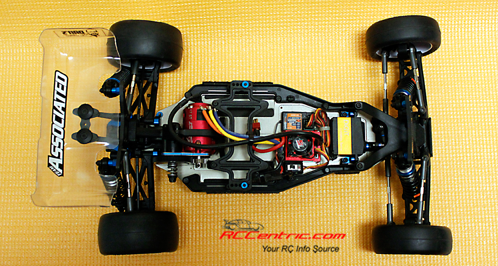
The completed RC10B6.
Running Gear
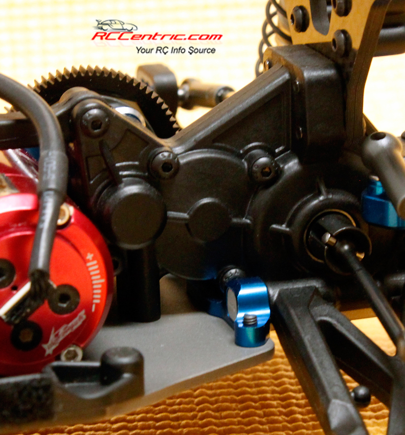
The 3 gear laydown transmission mounted on the B6. The TrackStar 17.5 motor is to the left of the frame.
To power the Team Associated RC10B6, I selected a budget friendly ESC/motor combo. I went with the Turnigy TrackStar 80A Turbo Sensored Brushless 1/10th ESC and a TrackStar 10.5TV2 Sensored Brushless Motor. I also have a TrackStar 17.5 Sensored Brushless Motor. for stock class. Both motors and the ESC are ROAR approved. I picked up a new Gens Ace 4600mAh 7.4V 60C 2S2P HardCase LiPo Shorty Battery Pack to provide the juice. To steer the B6, I went with a trusty Savox SC-1256 Coreless Digital Servo.
While the above products can be purchased from various online retailers, I prefer to purchase my electronics from a local re-seller. JAX RC Recycle and Repair, which is run by Sean Larmond, offers excellent prices on a lot of new products, as well as carrying used RC products that are always tested and verified. Sean supports the RC scene in Jacksonville and the surrounding area. He can often be found at races with a canopy and bins full of parts and electronics. He can be reached via his Facebook group at the link above.
The tires of choice for racing on indoor high grip clay are JConcepts Smoothies and Bullet wheels. That is what most racers use at the two indoor tracks in central Florida. Since that is where I’ll be doing the primary testing, that is what I went with. Since I will be doing my 1st shakedown run on an old school, loose clay track, I needed some other tires. For the front, I went with JConcepts RIPS on the fronts and James Racing Flash 2.2 1/10 Buggy Rear Tires
and summary.
Track Test
While the RC10B6 is meant for high grip dirt, carpet and turf, my first track test took place at a new track with loose dirt. There were two reasons for this. 1) I couldn’t wait to run the car. 2) The following week was the first race of a points series at a high grip track. I didn’t want to show up at the points race having never run the car at all. I wanted to use it as a shakedown run before the big race.
The first test took place at Cross Roads Motorplex RC track in Jasper, FL. You can find out more info from their Facebook Page or their website. This was the grand opening of this small to medium sized track. The dirt was loose and loamy, as well as on the bumpy side. The track is the latest addition to the family-owned complex that already includes dirt and paved ovals for competitive go-kart racing, as well as, motocross, BMX and areanacross tracks. They host regional and national races. I can definitely see them hosting big RC races in the future.
For the first race, I started out with the basically stock settings as recommended in the setup sheet. As I mentioned in the build process, I went with the rear shocks mounted on the back of the rear suspension arms. This helps keep some of the weight behind the rear axles, giving some weight bias toward the back of the car. It also makes the car turn a bit slower and easier to drive. Both were things I was expecting to need. I also added a few stick-on weights to the rear of the car, to the left of the motor to add more weight to the back.
My tires of choice for this track were JConcepts RIPS on the fronts and James Racing Flash 2.2 1/10 Buggy Rear Tires on the back. I’ve used Rips many times before, but the Flash tires were new for me. The Rips are grooved tires while the Flash are small pins. Even though the class was open as far as motors went, I decided to run the TracStar 17.5. Since I didn’t know what to expect, I didn’t want to overpower the track.
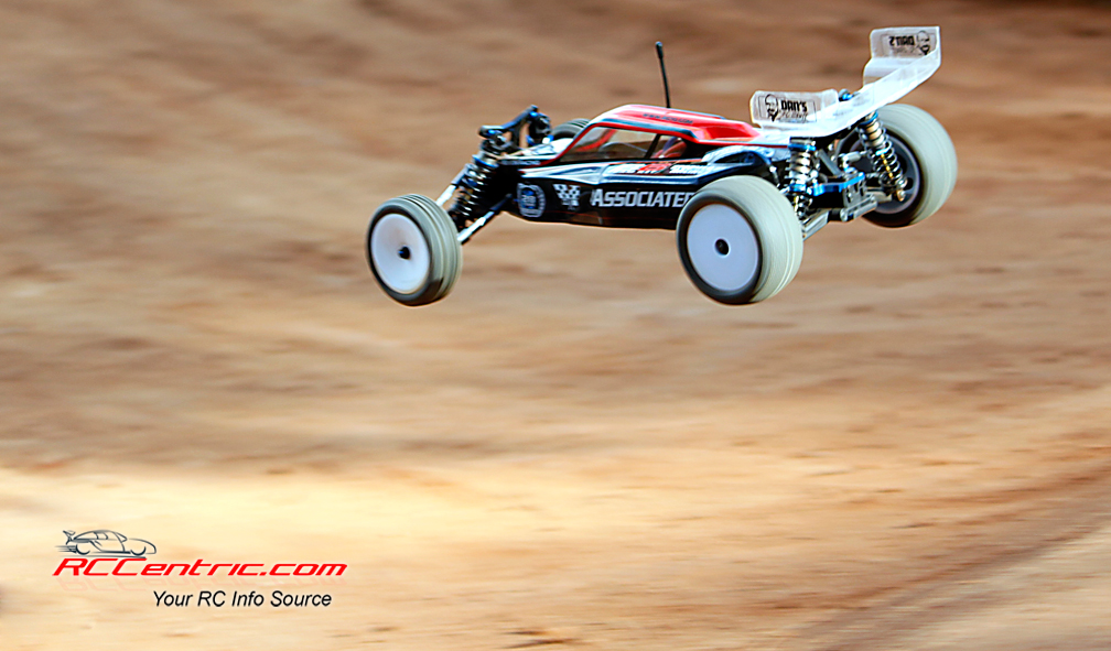
How did it go? Overall, it went well. The car jumped perfectly and cornering was terrific. I only got a handful of practice laps in, as I had to share the track with not only my class, but also stadium trucks, short course trucks, 1/8th scale electric and nitro buggies and 1/8th scale electric truggies.
The first heat race was really a practice run. As I figured, rear traction, when applying the throttle, was tough. It was in the mid 90’s, so the track kept getting pretty dusty. Both the 2WD buggy and stadium truck classes had some difficulty getting rear bite. It was a bit of a handful, for sure.
For the second heat race, I lowered the rear ride height by moving the shock collars up. My hope was that by lowering the ride height, and thus softening the rear suspension, it would allow the weight to shift from the front to the back on acceleration. This, in turn, would provide more rear traction. It did make the car more drivable and my lap times improved.
As the main race loomed, I decided to move the bottom of the front shocks to the innermost mounting position. The idea was to shift even more weight to the rear. It proved to be pretty effective, as my lap times improved yet again.
I feel I made some pretty good progress from the first heat to the main. I increased my total laps by two, between the first heat and the second heat. Since the main was a few minutes longer than the heats, I couldn’t really gauge the number of laps from the second heat to the main. Overall, I improved my average lap time by nine seconds.
For the second track test, I headed to Newred Hobbies in Ocala, FL. In addition to their website, you can find them on Facebook. Newred is a very high grip packed dirt track. It is a medium size track with a variety of jumps, hairpin turns, off camber turns and big sweepers. The track is indoors, so it is protected from the elements. Pitting is outdoors, however, it is all covered, with long benches, chairs and plenty of power. Newred Hobbies also features an extremely well stocked hobby shop with new kits along with most parts for the cars that are raced there.
In preparation for the second test, I turned to the RC10B6 Nation Facebook group. I simply posted a question, asking if anyone had a setup sheet for Newred in Ocala. Within minutes, Mike Olds, who works at Newred, responded and tagged a gentleman named Paul Wynn. Paul is one of the top racers at Newred and has been running the RC10B6 there for a while. A few minutes later, Paul posted his setup sheet to the group.
Paul’s setup sheet was pretty different than the stock setup. I used most every suggestion that Paul made. I changed the shock oil front and back, as well as, pistons in the rear shock, rear hub camber link location, different inserts in the C mount, lower rear axle height insert, lower front shock mounting location and ride height. The changes took me a few hours to make, but as I would find out, it was very well worth it. I also swapped out the tires for JConcepts Smoothies on the front and rear with Bullet wheels on the front and rear. Smoothies are, as their name implies, is a tread-free slick tire.
Practice went very well. Luckily, my friend, Andy McNeil and I arrived early. For the most part, I had the track to myself, which was a good thing. I was a bit nervous, what with a new car at a new track on a new surface and all. I started to get more comfortable and noticed immediately, that the car was glued to the track. It turned on a dime, jumped very neutrally and stuck the landing every time.
I got a bit too comfortable and at the end of the rear straight, I drifted too wide and hit the “Wall of Death” as it is known. I sheered the left rear suspension arm off the car, breaking it at the suspension hinge pin. It also mangled the C mount insert on that side. As luck would have it, the shop had a pair of arms in stock. I had spare C mount inserts and within 15 minutes or so, I was back on the track, none the worse for wear.
I entered the Team Associated RC10B6 in the Independent 17.5 stock class. This was a class for drivers that are not sponsored. Since Florida is a hot bed of off road racing, there are a large number of sponsored racers. It is a nice way to give the privateer racers a change to be competitive. For that, Newred should be applauded.
As I climbed the driver stand for the first heat, I was very nervous. I knew the car would be great. However, as this was my first race on this type of track, I was very jittery. Although this was the non-sponsored class, there were a lot of very fast drivers. As we took off, I found that the TrakStar 17.5 motor and Turbo 80 ESC was plenty fast. It had great torque and enough top end. Since the track was pretty tight, I was not worried about top end. Accelerating out of the corners was very important. The Gens Ace 4600 2s LiPo battery had plenty of oomph. I checked it after the end of the heat and it still had 80% battery life left! The car was truly amazing. I could place it anywhere on the track I desired. I was able to dive into the hairpin turns without worry of slipping or sliding. The JConcepts Smoothies were wonderful. My results were reflective of my driving and not the car. I could not have asked more of the B6. In fact, I was so happy with the setup, I didn’t make a single change to the car all day. There was no need to.
Heat two ended after two laps, when I suddenly lost steering. It was a shame, as my first two laps would turn out to be better than my fastest lap from the first heat. The servo horn had popped off the servo. This was not the fault of the car. I had used a servo screw that was just a little too short.
With a longer screw installed, I hit the track for the B main. At the sound of the horn, we took off. From my 5th place starting spot, I moved out cautiously, but did not want to get far behind the cars in front of me. By lap three, I was in 4th place and took advantage of some crashes to slip into 3rd! I was making up ground on the 2nd place car, but after a few bobbles on my part and a few scrapes with other cars, I slid back to 5th, where I stayed for the rest of the race.
I was very happy with the car and the progress I made from the first heat to the B main. I improved my total laps by over two laps, my fastest lap by nearly two seconds and my average lap time by two seconds. In my book, that was a great day of racing.
Summing It Up
All I really need to say is, WOW. From the packing to the build process to performance on the track, it was a total pleasure. The fit and finish of the parts was second to none. It is easily the nicest car I’ve ever built. No need to “persuade” any parts to fit. Every screw was able to be tightened snugly into the parts without fear of striping the plastic. It is also a very easy car to work on. Sure, there were some inconsistencies in some steps of the manual. However, Team Associated is aware of issues and is in the process of correcting them. Yes, I broke a suspension arm, but with a name like the Wall of Death, I don’t think it had anything to do with the RC10B6’s parts quality.
Performance on the track was truly amazing. I can’t imagine it being any better than what I experienced. I just have to get better at driving. The JConcepts wheels and tires were prefect for the conditions and look like they will last a long time on the smooth surface.
If you know you are going to be doing a lot of high grip dirt racing or running on carpet or turf, I would go with the RC10B6 without hesitation. If you think you are going to be doing both dirt racing and also high grip dirt/carpet/turf racing, I would recommend you go with the RC10B6D. You can get a conversion kit to go from the standup transmission to the laydown transmission for under $30.
You can get the RC10B6 Team Kit (90011) or the RC10B6D Team Kit (90012) for around $310. Regardless of the type of off road racing you are doing, the Team Associated RC10B6 and RC10B6D are the way to go. |