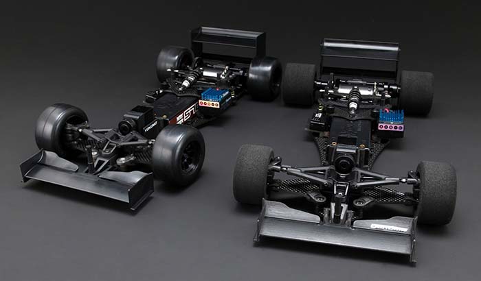
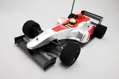
Car Formula "YRF Formula 001W" for the competition that enables sharp ride. We'll explain with photos to maximize its performance, chassis fabrication. In the assembly instructions detailed that comes with the kit, basic goes up a set without problems assembled along the content, extract a portion of it, plus a commentary that focus point, where he will continue to explain clearly course.
YRF Formula 001W Manual [PDF5.68MB]
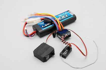
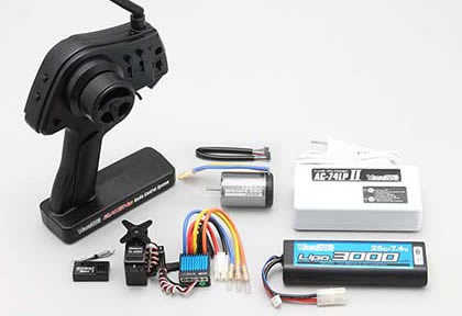 In addition to the YRF-001W Chassis Kit (using the YF-HN ? 2,000 in this case), which provides first is prepared paint only polycarbonate, pinion gear, transceiver, steering servo, speed controller, motor, battery body for Formula Car it is necessary. Here we use (DP-RS215H ? 27,000) YOKOMO running brushless specification set 2.4GII / Li-po battery high speed servo.
 Apart from the tools that come with the kit, so you can be prepared Phillips screwdriver (small), cutter, scissors, needle nose pliers and nippers.
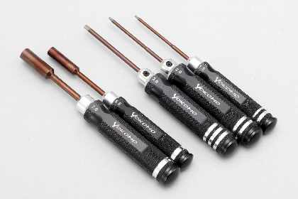
 Required tools are also included in the kit are available separately tool more useful. RC car is handy to have a more precise, easy-to-use tool, so many scenes, such as maintenance after the running tool active. Yokomo wrench series of photo works.
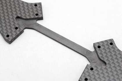
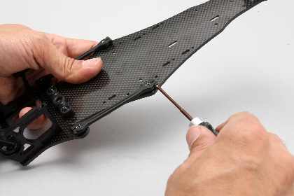
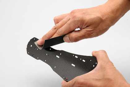 Carbon parts, such as front lower arm and main chassis, carbon fiber since it can splinter angle of the cut surface is turned sharp, rounded corners, etc. keep water-resistant paper about # 400. Since prevention of injury in this way, you drop the angle carefully, etc. on both sides of the main chassis many opportunities to touch the hand in particular.
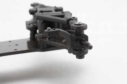
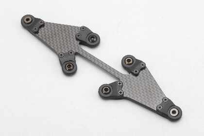 First assembly of the front suspension arm. Since there are two sides to the top and bottom of each part, we will proceed with making sure that each not to make a mistake.
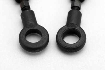
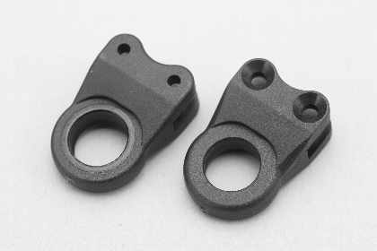 (Pictured right) will be on the upper side there is a better processing of the screw mounting plate, lower arm ball end would be put in suspension arm ball from the bottom.
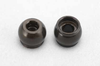 Do not confuse King and pinball ball suspension arms are similar. (Right) King pin ball shall have depression.
 Lower Suspension Arm is being cut thin side facing the bottom plate.
I scratched the ball and end when you put the ball in the ball absolutely suspension arm ball end, and sandwiched between the needle nose pliers. Using (R12-36 ? 980) Pivot ball tool has been released for 1/12 racing, such that when installed without damaging can be wasted. When removing the ball is the size of the ball does not fit in the cup of the pivot ball tool, you are good, such as a spacer and sandwiched F8mm bore pipes and bearings.
|
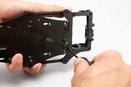
 When the lower arm is attached to the chassis, so that little by little we will tighten in the order of the four screws. As for other parts, having a structure to support a few screws part one, go on evenly tighten Kon is the theory.
 As you can see the mounting direction of the lower arm. Although I do not think so wrong to interfere with the front and rear suspension mounts is reversed, I want to be careful not to make any mistakes up and down as well.
 Care must be taken to be two sides of the upper arm ball end. Side (right) there is a muscle in the upper around the hole, insert the ball from here as well.
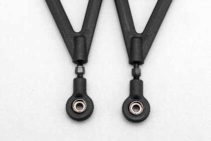 Turnbuckle tie rod of the upper arm, careful to enter straight into the screw holes as much as possible. Habit because they come out here to the left and right corners and bent, try to work carefully.
 Sasupin through the upper arms, I'll keep to ensure that they operate smoothly.
 You can change the amount of trail by the front axle can be swapped around. 4mm trail and it will be inline, behind and to the front side axle shaft.
 Axle is mounted so as to not confuse the top and bottom. Arm of the knuckle on the ball downward to become correct. I'll check the knuckle moves smoothly at this point, of course.
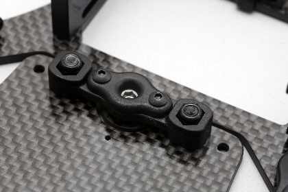
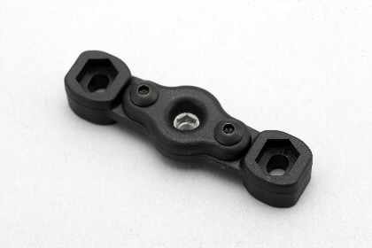 Let's get down to the production of around rear. Centrelink first. When tightening the screws on both sides of the Sasuboru, note the movement of the ball so that it will not interfere. When I later joined with the main chassis, I will adjust the clearance again.
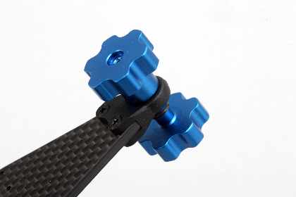
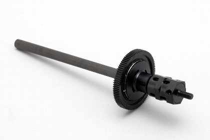
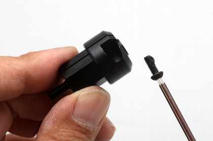
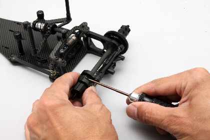
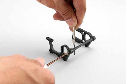 Joined by a shaft to the left and right rear bulkhead. During tightening of the screw shaft so they turn together and secure through the hole in the shaft and narrow L-shaped wrench or screwdriver.
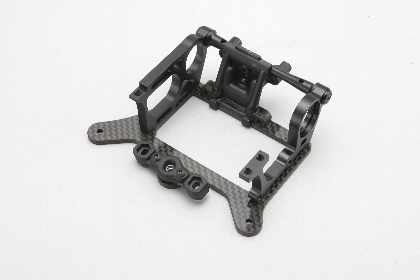 You just be careful that you tighten the screws evenly, fixed Roaburesu ought to set up without any problems. Do not forget to attach a rear wing mount at this point.
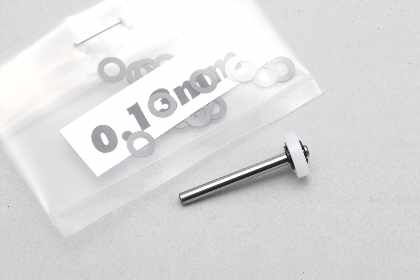 Let's move on to the production of the rear damper. X large shock, but are included with the pitching damper, backlash and wear as it is slightly out of the piston to the shock shaft. There is no problem as is level, taking the backlash by the E-ring interposed between the piston and can be (here using 0.13mm) thin shim or the like.
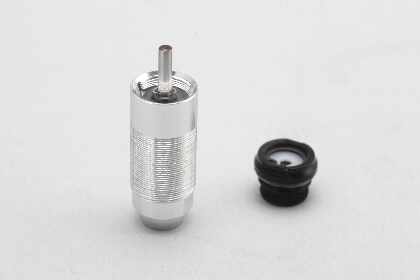 I put the oil in the cylinder, I pushed back as far as it will go pull the piston shaft with bubbles. Put the cap remain shortened, so that the excess oil out of the overflow, I will tighten the cap slowly. Increased pressure in just before the cap is completely closed, and the shaft should come natural growth.
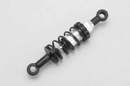 We will confirm by actuating the damper fully closed the cap, moves smoothly to the most contracted state. Also, depending on the amount of oil, such as in this case, the difference will appear in the back of the shaft repulsive force, the accuracy of the setting will go up if you can as equally Kumeru anytime. Install the spring and damper complete end.
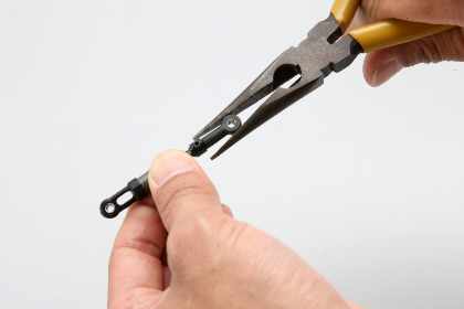 Because some of the damper end tight clearance with the ball, and each ball end pliers scissors strongly on the radio, it can ensure adequate clearance.
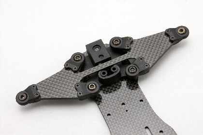
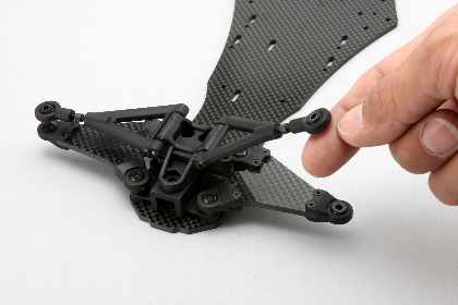
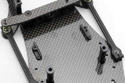
 Joining the main and rear part of the chassis. Suspension link rod adjustment movement of the ball to move smoothly without backlash. Make sure to move in various directions around the rear.
 Center fixed link is performed after mounting the rod. Taking care Roaburesu chassis and as much as possible so as to be in parallel, I tighten the fixing screws of the rear suspension link. Fixed after confirmation of the movement around the rear again
Link rear suspension is too tightly, there is a movement that is extremely bad, such as when the shift was crash. Good, including the meaning of the anti-loose, it may be useful to change the nylon lock nut from the nut flat nuts.
|
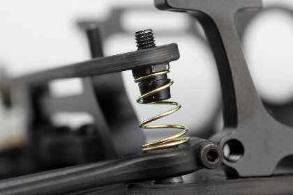 Spring roll, push the rear groove of the holder as far as shown in the photo.
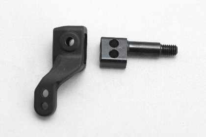
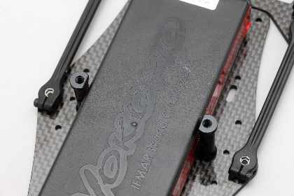 Stopper battery post is fixed on a flat surface is facing (toward the battery) inside. As with the rear bulkhead post, I fixed through the side holes of the post, such as L-shaped wrench they will not get along with the screw is turning.
 Battery to be used if you are determined, you would attach the battery stopper at this point. If you plan to install a pro-pack or back straight, short Li-po battery, cut the L-shaped portion of the battery stopper.
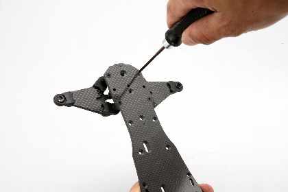
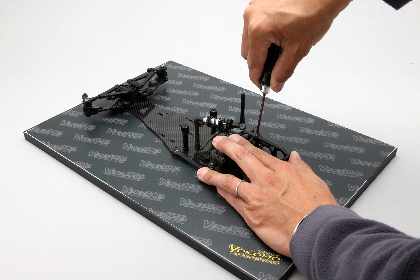 Not to twist out to Riyabaruku, when fixing the upper brace, work place the chassis on a flat surface as much as possible. It's nice to have a setting board. Once you remove the damper as well, you have to loosen the tension of the spring, to avoid stress to the upper / Riyaburesu.
Yokomo setting board 2
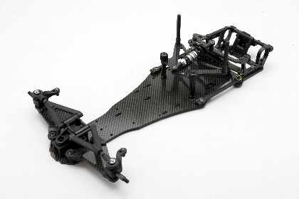 Seems to have become very much in this chassis. Let me check again the movement around the front, rear suspension link, if there is a margin of damper.
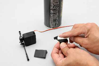
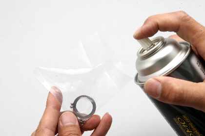 Before assembling the ball diff, degreased with the cleaner and Defuringu Diff. These parts oil to prevent rust has been painted, def becomes slippery under the influence of the oil and continue to use it. OK and put a ring ball bag, parts, even just a small amount of spray cleaner in it.
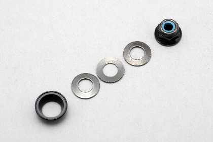
Spring washers usually one has been used in the thrust cone tightening the diff, I can increase the width adjustment by increasing to three pieces can do this. By attaching the three together alternately, effectiveness of the diff I will be easy to adjust.
|
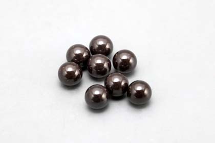 
By changing to a ceramic Diff, that make up the def smoother I will be possible. To minimize contact with the ring in preventing and improving the accuracy of the surface of the ball, the deformation of the ball when it is tightened, it's a part of you gotta def lighter, non-slip is completed.
Ceramic 1/8 Diff Ball for YOKOMO R12 (8pcs)
|
 Effectiveness of the ball diff is an important point that affects the driving characteristics of the direct drive machine. In the road surface slippery super but may also be set to push understeer to heavier Def, increase the maneuverability is usually actuated lightly because theory, I want to keep the good condition by regular maintenance.
Striking the side to the fence, so often on the outside of the hub bearing is damaged right, I'll check it out when the differential is no longer around to smooth.
 Hoiruhabu the left clamp. You must be tightened with a surprisingly strong force, it can be fixed smoothly and keep a small amount of black grease is applied to the mounting screws.
 When fixing the left hub is fixed to the left and right appear slightly much backlash. In the stationary state even if the rotation would be perfectly smooth and may rotation is spoiled when the twist occurs during running.
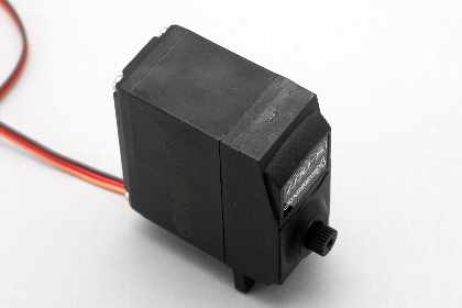 It is equipped with mecha finally end. First, from the steering servo.
The servo mounting stay, and cut with cutter and nippers. Surface in contact with the chassis will keep the flat cutter. The upper left is no problem, because it interferes with the body in many cases, it is going to be cut as well.
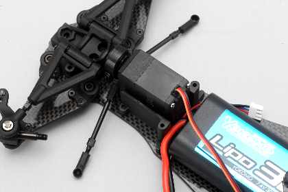
By using the short size Li-po battery in, attach the steering bell crank conversion of options, set closer to the rear of the servo can be adjusted closer to rear weight distribution is possible. Steering response is also increased by the weight of the front is reduced, allowing quick cornering.
Steering bell crank conversion set for YRF 001 series
|
 Once connected servo and ESC, receiver, battery, check the neutral position of the servo. By mounting the servo horn to the neutral position, I will be able to correctly set the width adjustment of the steering.
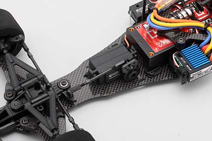
 Once the servo stays fixed to the chassis, make sure the mounting position of the servo, the clearance of each part. Contact of the front arm of the servo horn when you move the steering NG. If you install a battery pack straight, you make sure that the battery may fit neatly.
 But with mechanical know-how that are common to, the adhesive force is difficult to peel up the adhesive surface of the double-sided tape and keep clean with a cleaner. Sometimes it comes off in the mechanical and driving Neglecting to do, I do firmly to prevent trouble.
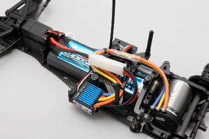 Maneuverability of the code is difficult due to the narrow body, if you use a running set it will be something like this. But care must be taken to prevent movement of the rear suspension link hampered by the movement of the code.
 You may link the movement of the suspension will be even worse in the interference with the body. With the body of the plan that will actually be used to make sure there is no interference with the body by moving the rear around.
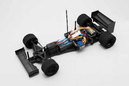 Chassis is now complete. Switch on the transmitter and ESC, initial setup and check the movement of the ESC, I'll go to the rough alignment of the steering trim servo.
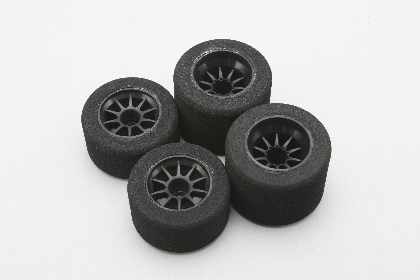 There sponge tires and tire grip strong, and high sense of scale rubber tires, you have described how to put a sponge tires here. There is also preformatted tire adhesion, of course, that it is cumbersome to assemble pre-adhesive can be selected.
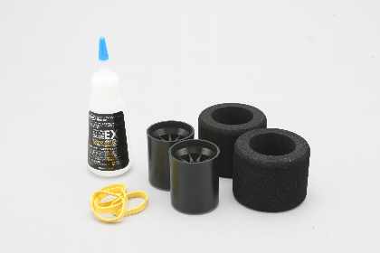 In addition to the wheels and tires, instant adhesive for foam tires to prepare the (CS-SGST ? 1,380), for bonding rubber band tires (YT-WG ? 120). Adhesive strength is weakened, can be used (such as bond G13) instead of rubber-based adhesive glue.
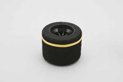 Adapt to fit the tire on the wheel, I first determine the position of the tire. They are usually mounted inside out according to the outer wheel, the front tire width is too wide, it may interfere with the knuckle. The reception is better with respect to adhering to the criteria on the inside, the better. Although the adhesive bond by half from both sides, put a rubber band on the side that does not adhere First, in a fixed position to prevent displacement.
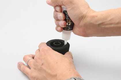 I turn the nozzle pushes half the nozzle of the bottle of glue, like muzzles and turn along the wheel while scratching out a few drops of glue minutes. It is also required quick work of the task force in its own way you are, this area will also need to get used to.
 Ideally extent to which the adhesive seeping slightly from the edge of the wheel. I'll keep wiping tissue, etc. before the glue that exceeds the firm.
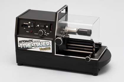
Sponge tires sometimes leaves some distortion of molding condition and adhesion by the situation, in order to maximize the grip force to cut out a circle in the setter and tires is the best policy. Because it can also bring out the best performance tire diameter finish you have in mind, I asked for a better performance in the race, it would not hurt to be prepared setter tires.
YOKOMO Tire Truere (w/Hub for R12 ·w/Hub for R5.1)
F-1 Wheel Hub for YOKOMO Tire Truere |
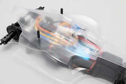
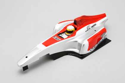 The body is made of polycarbonate is mainstream. Cut along the cut line, only painted with paint polycarbonate. Installed in the chassis, so you may want to interfere with the front steering tie rod and rear bulkhead, and can be rotated to adjust the cut to fit the situation.
Lacey scale atmosphere and the decals.
 This completes the work of one street. I would have been a satisfactory finish. The final tweak it is necessary to finish while running of course, I would like you to check the circuit means that the difference between the No! Mistake that also increases the quality of the ride and keep tightly assembled at an early stage.
 Ball differential with respect to the assembly of the YRF-001
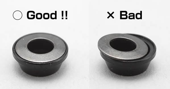
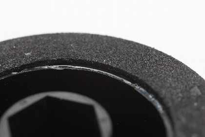
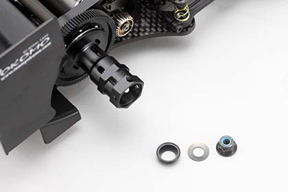
While we received a voice about the formula car · YRF 001W we launched this time, "Your ball diff is not working nicely" with, and Gorigori when you when you crossed the ball diff in the early stages, it was operated diff you feel is most likely damage the thrust bearing in the right Hoiruhabu. It has been confirmed that it works without any problem if it can build up to as assembly instructions, when I would tighten the 4mm nut (see picture below ?) state Belleville washer and the thrust cone is shifted, the bearing excessive force, preventing actuation of the differential bearing such as internal distortion has been confirmed.
Damage the bearings once because it is difficult to play, when the assembly of the ball differential, we ask that you please confirm that the Belleville washer fits into the thrust cone throat quite satisfactory.