Overview
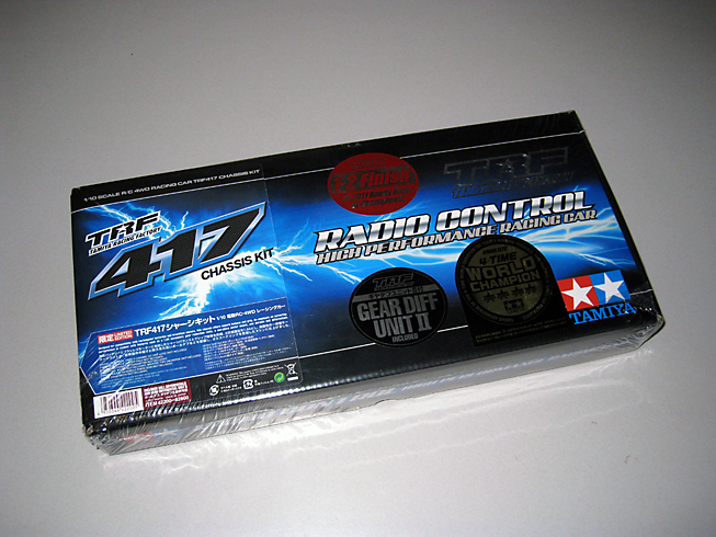
The TRF417 is based on the 2010-11 IFMAR ISTC World Championship-winning chassis. Created using valuable race data gained through races with the TRF416, the TRF417 features several key improvements:
New design features:
Front/Rear Carbon Damper Stays
Front/Rear Aluminum Bulkheads
Aluminum Motor Mount
Aluminum Center Shaft
Aluminum Diff Joint
Aluminum Steering Arms and Linkage
Diff Plates
Wheel Axle
Cross Joints
19T Pulley
Carbon Lower & Upper Decks
At first glance, these changes may appear small. However, in the competitive touring car world, they are significant and result in a very noticeable difference in the balance and handling of the car. The chassis design and layout has been fine tuned specifically to optimize weight distribution for Lipo batteries, brushless motors and the new minimum weight restrictions (1,350g). The one piece motor mount adds rigidity for today's high powered motors while the use of 19 tooth center pulleys further improve drive-train efficiency.
The new steering system is now separate from the upper deck. This provides more flex at the front of the chassis, improving steering feel and consistency. The rear differential features a new larger housing and notched plates. This improves the life of the differential between rebuilds as well as improving the consistency of its operation. The TRF417 Kit number 42200 includes the Tamiya optional gear differential unit (item 42197) in addition to the ball differential.
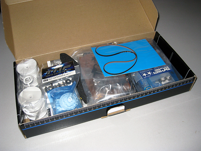
Building Tips
Assembling the TRF417 is very straight forward with typical Tamiya quality and fit but there are a few tips that could be helpful for some builders. Also, I would recommend incorporating the following Hop-Ups into the build:
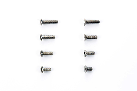
TRF417 Titanium Screw Set - 84178
This Titanium Screw Set for TRF417 machines will help you save approximately 20g.
Specs & Features:
- 3x6mm Hex Screw x 16pcs.
- 3x8mm Hex Screw x 17pcs.
- 3x10mm Hex Screw x 7pcs.v
- 3x12mm Hex Screw x 4pcs.
- 3x6mm Hex Countersunk Screw x 19pcs.
- 3x8mm Hex Countersunk Screw x 26pcs.
- 3x10mm Hex Countersunk Screw x 6pcs.
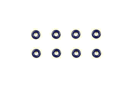
Competition O-Rings - 42137
These competition O-Rings (P3 size) are made from a unique silicon giving you the extra support you need when racing. They have excellent durability qualities, apply minimal friction to the dampers which helps prevent oil loss, and can also be used in extreme temperatures (-80 degrees Celsius) with little to none shape deterioration.
One pack contains 8 O-Rings.
Can be used to replace P3 O-Rings installed in oil dampers such as CVA and TRF dampers.
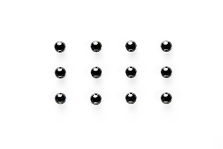
Ceramic Differential Balls (if using the ball diff) - 42142
Compared with other steel and tungsten ball diffs, you will be very happy with the precise and smooth action as well as the longer maintenance cycle this Ceramic Ball Diff. offers to TRF machines.
3mm Ceramic Ball Diff X 12pcs.
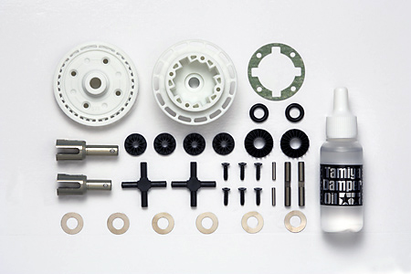
Gear Differential (if it's not included) - 42197
The use of a gear differential unit is becoming a major trend in the touring car class that use very high power brushless motor technology. The Tamiya Gear Differential Unit uses oils with different viscosity to attain adjustment, which results in optimum power transmission from the high-power brushless motors in the market today. It also improves traction and acceleration. TRF Driver Marc Rheinard uses these units in the front and rear of his TRF417 when racing on carpet to minimize diff rebuilds that are common when using a traditional ball diff unit. The unit is fully enclosed and the built-in gears are less likely to wear out compared with ball differentials.
Specs and Features:
- TRF417 Gear Differential Unit II x 1pc.
- Aluminum Diff Cup Joint (exclusive to this item) x 2pcs.
- Bevel Gear: 12T/20T (Item 42185 TRF417 Gear Differential Unit includes bevel gears with 10T/20T).
- Compatible with TRF417, TRF416, 416WE 416X chassis machines.
- Silicone diff oils of 100000 weight are recommended as a starting point for the front and 1000 for the rear.
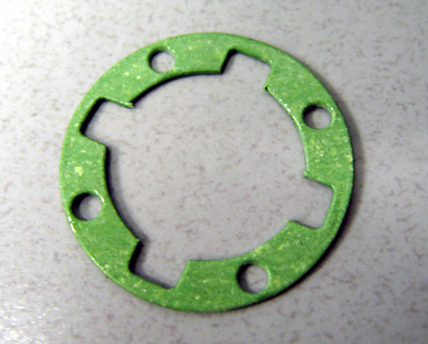
Assembly tip! Use Green Slime or any type of sealer grease commonly used for R/C damper shocks for the gasket and rubber o-rings. This will create a better leak free seal between the diff cases.
Bearings
Typically, it is common practice to take all the ball bearings and clean the grease out with contact cleaner, then oiling them with light bearing oil. This is done to improve the drive train efficiency and overall speed. The compromise is reduced bearing life because the grease seals out dust and debris better than the oil. The TRF417 however, comes standard with a complete set of Teflon bearings. These bearings are packed with much lighter grease and have a minimal effect on speed and efficiency so I prefer to use them as is.
Gear Diff
Gear differentials provide excellent corner speed and traction. They also require less maintenance and have become very popular for touring cars for these reasons. So much so, the TRF417 kit (42200) now includes one as a standard feature. If you have the earlier TRF417, the gear differential is available separately (42197) and can be used at the front and rear.
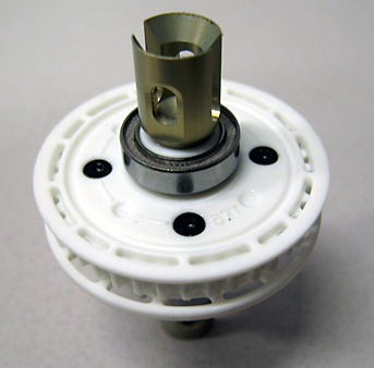
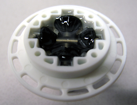
During assembly, it's important to coat the two black 5mm O-rings with silicone fluid prior to installation. This is not called out in the instructions but it helps insure a good seal. When removing the small and large bevel gears from the parts tree, make sure to cleanly remove them so there are no burs where they were attached. When filling the differential with silicone, do not fill it completely to the top. You should leave some space for the other half of the differential and bevel gear (see picture).
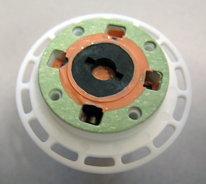
Before installing the gasket, coat it with a thin layer of silicone to improve its ability to seal. The gear differential is adjustable by changing the viscosity of silicone fluid just like the 1/8th scale off-road vehicles. A good starting point is 1000 weight silicone fluid.
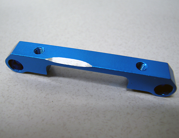
Because the TRF417 features symmetrical bulkheads, the gear differential can be used in the front to provide more mid to exit steering. Using a gear differential in the front requires very thick silicone such as 300k (300,000 weight) and higher. A popular alternative to silicone for the front differential is to pack it with cleaning putty or for an even thicker alternative, you can use silly putty. Slight modification to the suspension block may be required when using the gear differential in the front. The gear differential housing is slightly larger in diameter and can contact the mid front suspension block. To fix this, simply grind a little material away for clearance.
This gear differential is packed with silly putty. Note that the spaces behind the small bevel gears are kept free of putty. This is to allow the other half of the differential to fit during assembly.
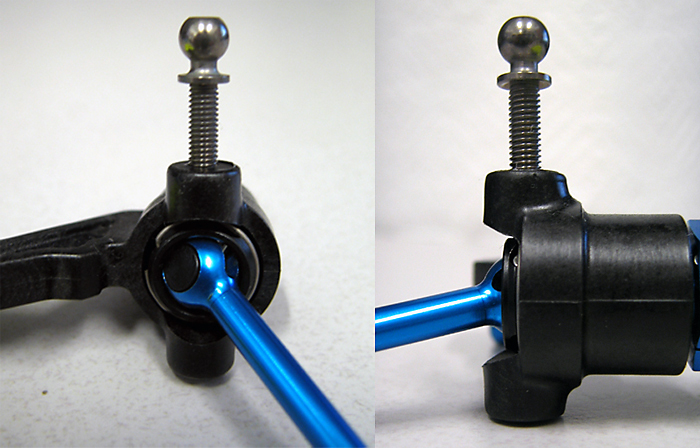
Front steering knuckles
Smooth and bind free steering movement is essential to achieve a predictable handling car. The steering knuckles can bind if the king pins are not threaded in straight. An easy way to insure proper alignment is to pre-tap the threads prior to assembly. This makes it easier to confirm that the kingpins are going in straight which will eliminate binding in the steering system.
Begin by taking the king pin (5x9 ball connector) and thread it in into the steering knuckle just enough to start a couple threads. Stop and make sure the king pin is straight by looking at it from 90 deg perspectives (side and back). If the king pin is at an angle, push it in the appropriate direction and continue threading in the king pin while stopping periodically to check for straightness. Once the threads are completely tapped, remove the king pin and repeat on the other side and on the other steering knuckle. After this is completed, you can assemble the steering knuckles as per the instructions.
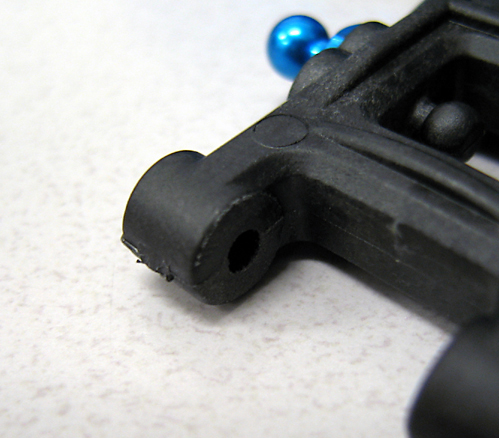
Rear suspension arms
When attaching the rear hubs to the suspension arms (step 13), you will likely need to sand or file the suspension arm to eliminate binding. I used a small file to remove just enough material to allow free movement of the rear hubs. Test fit and file as necessary so that you don't remove too much material.
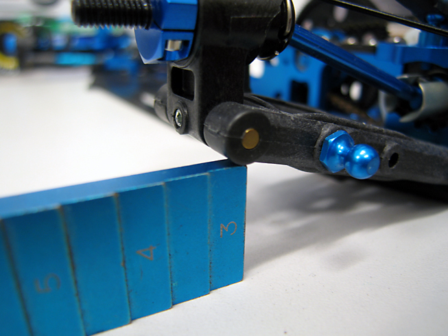
Setting stabilizers
The stabilizers help control weight transfer when the car is cornering so it's important to make sure the balance is set evenly. After you assemble and install them as per instructions, remove the shocks and set the height of the suspension arms so that the right and left are the same distance from your setting board. The exact height of the arms is not critical at this point, only that they are even and are moving freely without binding in any way. I normally measure from the top of the axle but because the camber has not been set, I'm measuring from the top of the arm.
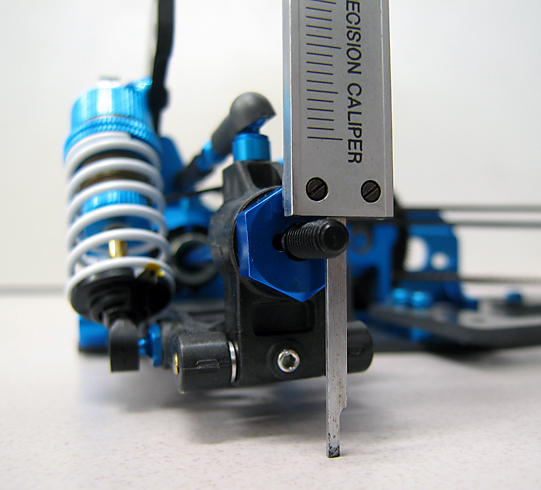
Lift and place and object around 15mm - 20mm thick under the suspension arm (I use a Tamiya ride height gauge) and measure with a vernier caliper with a depth gauge and note the height that the opposite arm has risen. You should tap the side you are measuring and measure a few times to insure an accurate reading.
Repeat this by raising and measuring the other side. If one side is higher or lower, adjust the linkage on that side. Lengthen it if it's higher and shorten it if it's lower, then re-measure. Repeat until both sides are even.
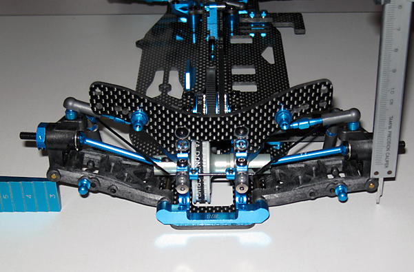
Setting Droop
Droop is the amount of distance the suspension is able to move downward when completely unloaded. Before setting droop, set your camber and ride height first. Once camber and ride height is set, place the chassis flat on your tweak board without wheels attached and measure from the top of the wheel axle to the tweak board with a vernier caliper (this should be done with the shocks attached). Make the left and right side the same by adjusting the set-screw in the suspension arm. A good starting point is 25mm front a rear.
This method tends to eliminate error that would otherwise occur when changing anti-squat or anti-dive and/or raising or lowering your suspension blocks. Regardless of what you adjust on your suspension, your droop reading will remain consistent. There are other methods and if you're comfortable using a different method, continue doing what works for you.
Conclusion
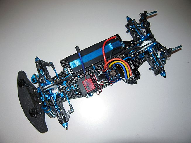
Building the TRF417 is a quick and struggle free process so there isn't a long list of tips and tricks but this is a good thing. It had been quite a while since I last raced or even drove a modified powered touring car. This build as well as a local race sponsored by Speedtech RC held at Tamiya America's test track gave me an opportunity to try out the latest Tamiya TRF chassis and also to race again.
Considering the long break from racing, I surprised to find I wasn't too far off the pace. After a few adjustments, I was competitive and managed to qualify second overall. The main was a single heads up race which I made a perfect start and immediately took the lead. Surprisingly, I went on to win after a brief battle that resulted in a mistake from my rival. As unexpected as this was, the credit should be given to the car and how well it handles.
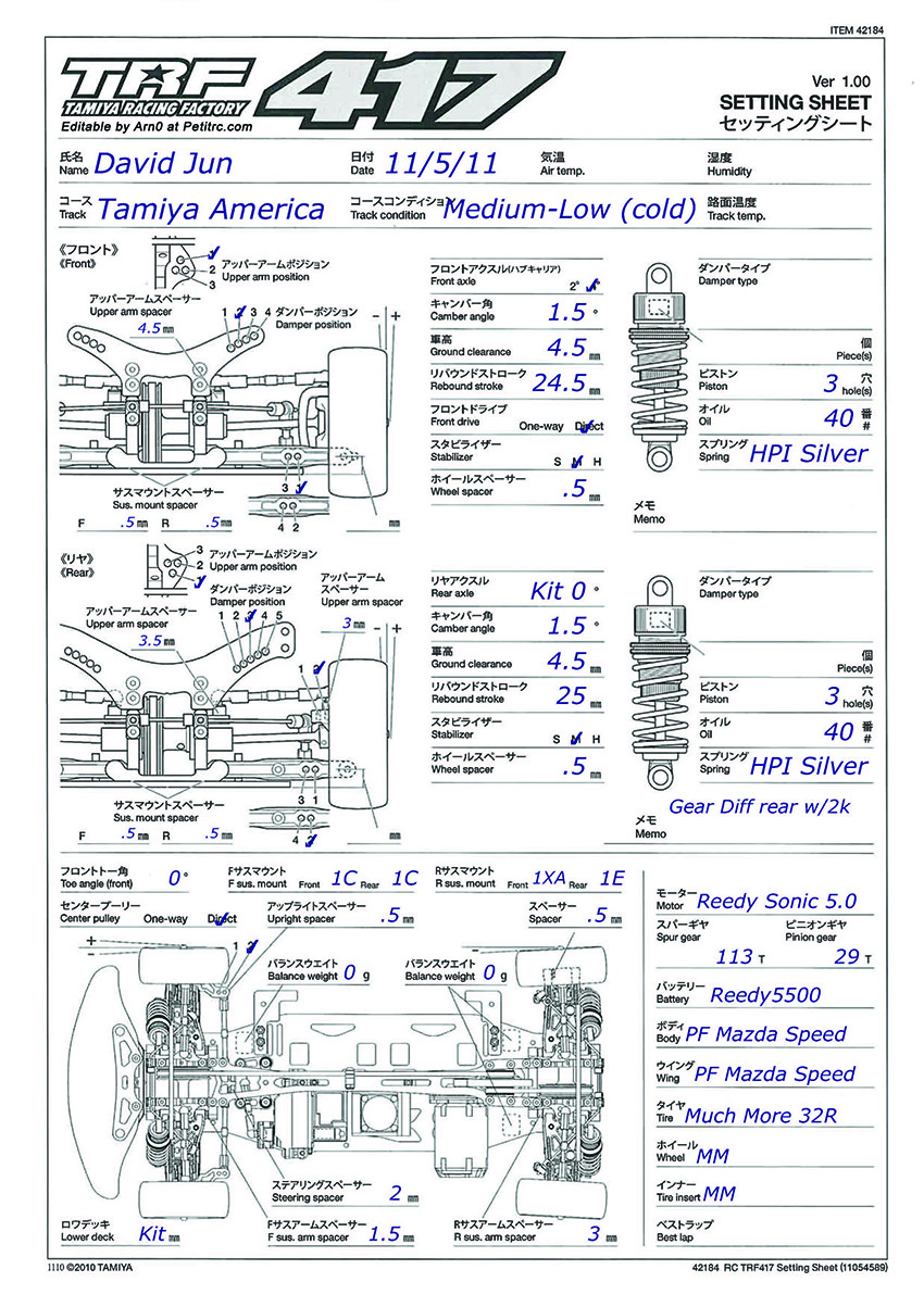
The following is a list of the electronics that I used as well as a set-up sheet for the race: