As regular readers will know, I have been interested in and impressed by the Gizmo GZ1 since it was announced.
Rumors about the car and various prototypes being tested in Denmark had been around for some time, but all this was kept very quiet until pictures and information was released late 2015 at the first ETS round of the 15/16 season.
While briefly visiting Round 2 of the ETS in Germany in early February, I had the chance to see the car myself, and the quick look left me impressed.
With the car now available, I thought it was time to really get to know it.
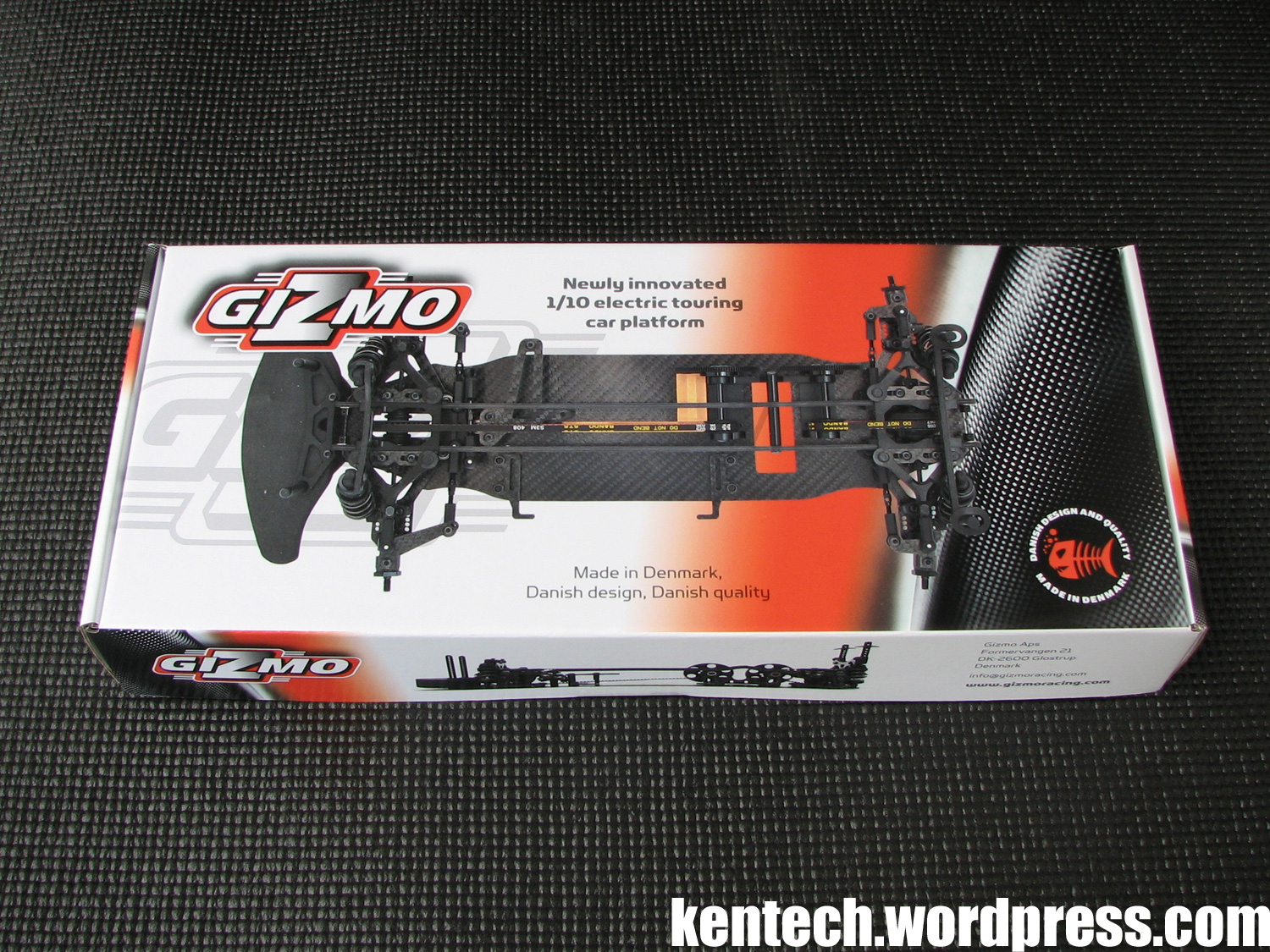
The GZ1 comes delivered in a fairly small box, packed full of stuff, with pictures of the chassis from different angles covering each side of the box. A personal favourite on the kit box is the the fish logo (“Danish design and quality – made in Denmark”), which I remember well from the excellent Fish tyre additive of many years ago ;)
Bet most of you don’t remember or know of that one!
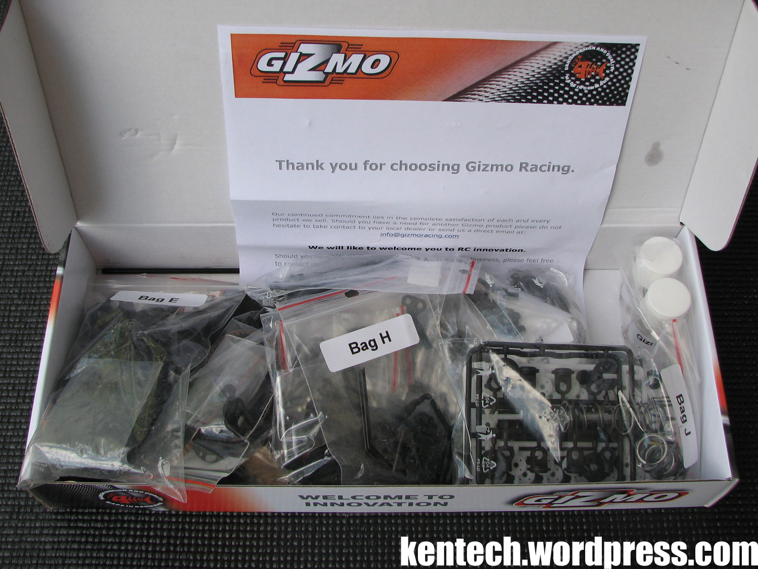
Inside the box, the parts are packed in small zip bags (marked Bag A, B, C etc.). All screws are also packed in separate bags, clearly marked by scew type and size. The included screws are black steel screws of good quality.
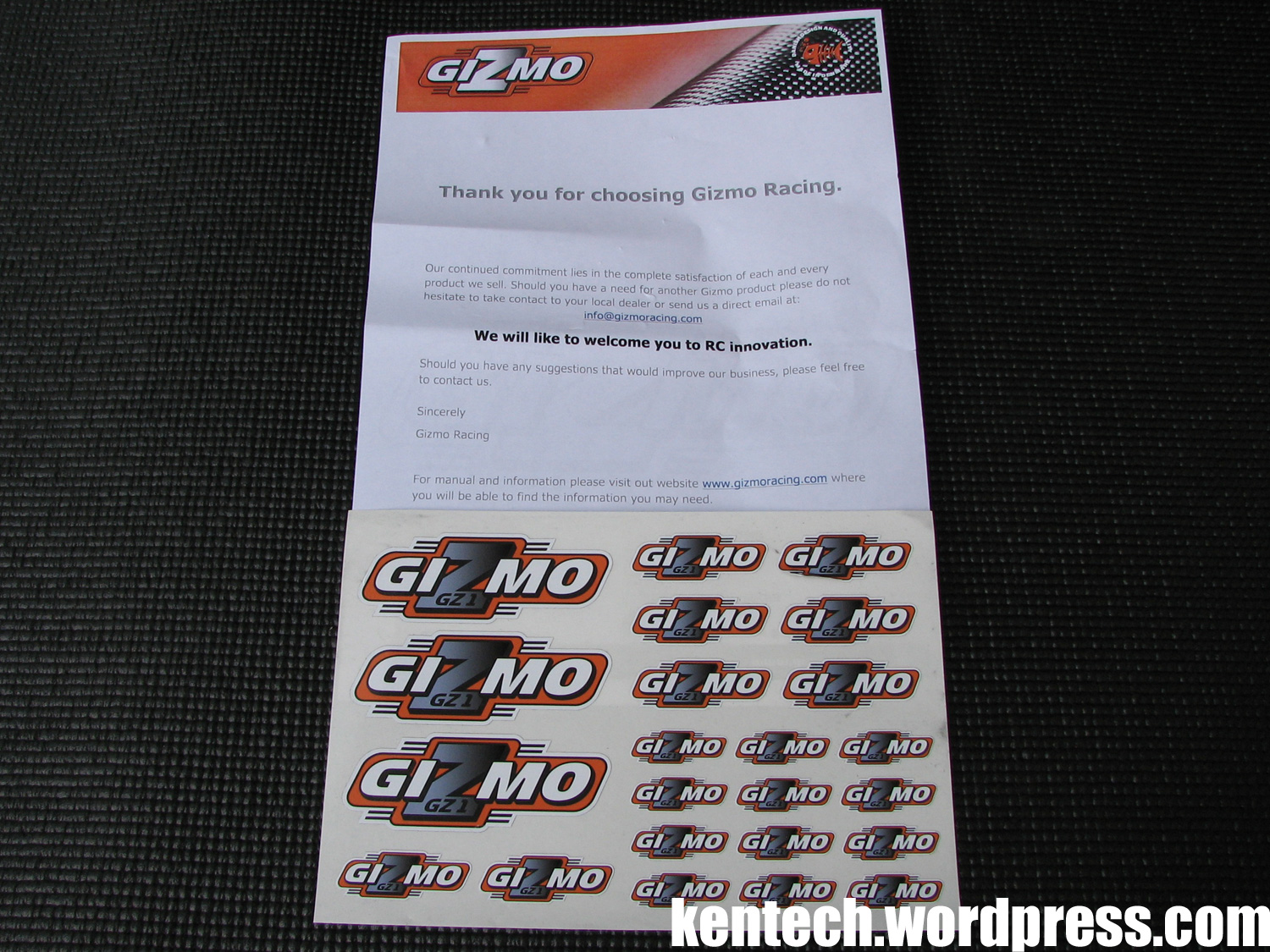
You get a thank you/welcome letter and some Gizmo stickers, but no printed manual. Just like many products today, the manufacturer offers the manual for download, saving cost and shipping weight, while allowing to constantly update the manual online.
While most parts are packed in bags, the main frame parts come separately inside the box.
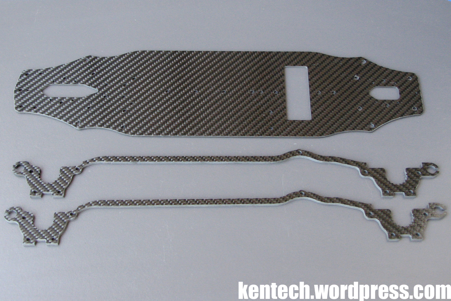
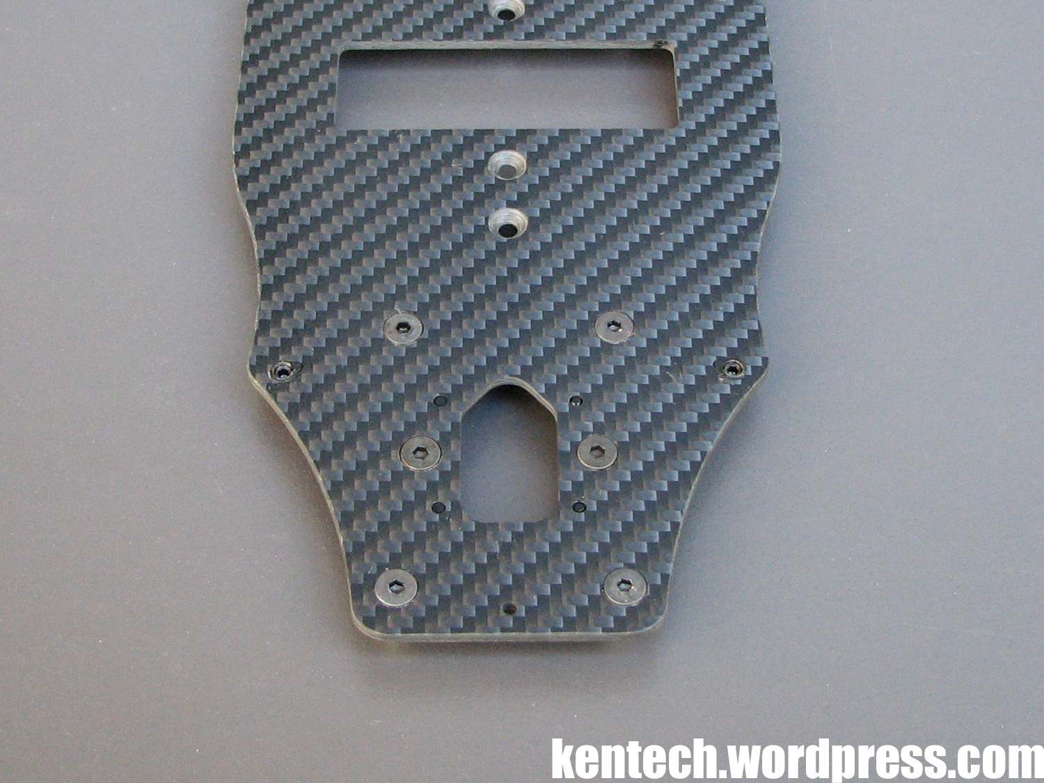
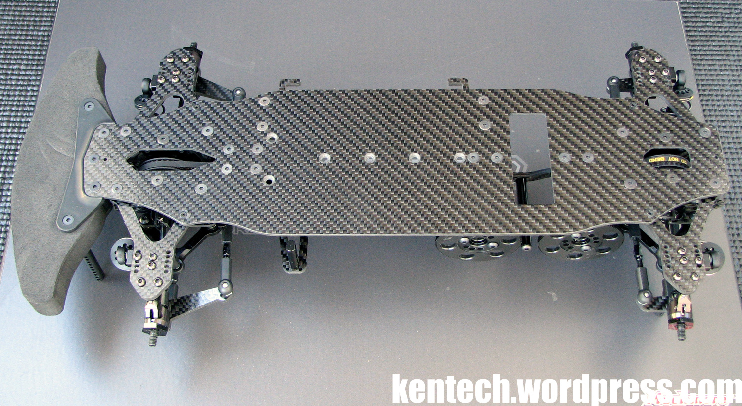
The carbon fibre chassis plate and side plates does not use a similar material as many of the larger manufacturers do, as can be clearly seen in the picture. The carbon material type used (called different things by different suppliers) has more fibres and less epoxy, and a different pattern compared to the ‘normal’ RC material. Because of it, this type of carbon fibre is usually stiffer and lighter. The GZ1 chassis plate is certainly fairly stiff for its thickness.
Specs:
Main chassis:
– thickness: 2.0mm
– width: 87mm
– weight: 66g
Side plates:
– thickness: 3.0mm
– weight: 11g (1pc)
Time to start the GZ1 assembly then!
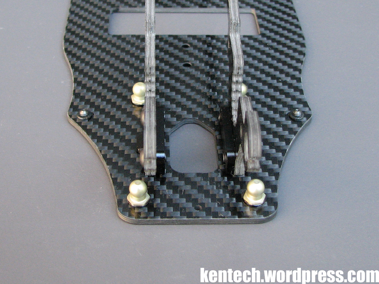
The first step is to mount the suspension balls to the chassis plate. The balls are light, made from aluminium and coated, with a low friction finish. The balls are the same front and rear, and when built according to the manual there are 0.5mm black anodised aluminium spacers (which are included) under each ball.
Also seen in the picture above are the downstop collars and screws. The plastic collars need to be pressed (or glued, but I did not see a need to glue them) into the chassis first, then the plastic protruding below the chassis needs to be cut flush, after which you can add the adjusting grub screws. This is the same as on Awesomatix cars, and the collars are indeed an Awesomatix part, used by Gizmo. It might sound complicated, but isn’t.
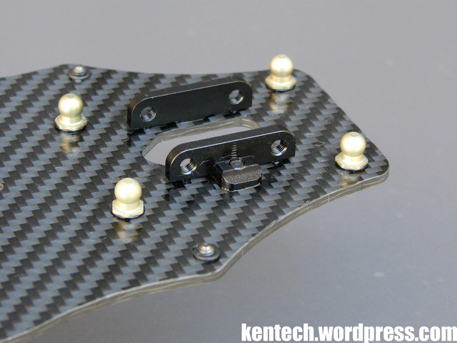
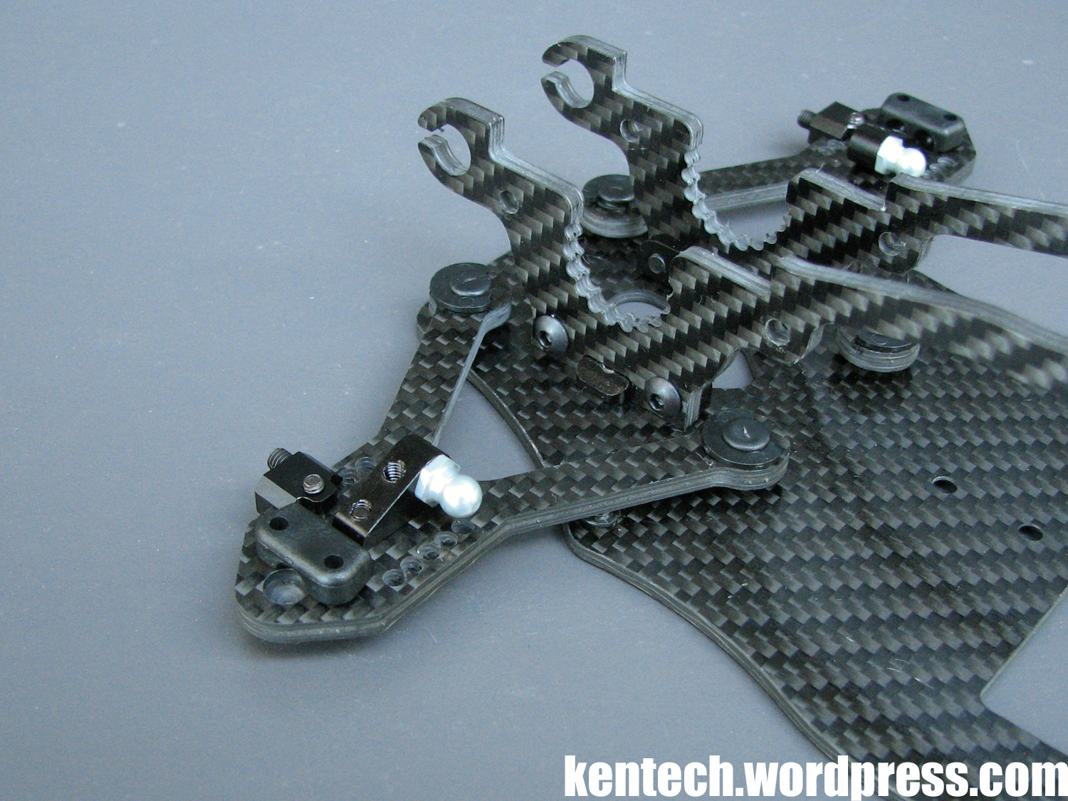
The next step is to fasten the aluminium side plate mounts to the chassis, and already here this design differs totally from all others currently available. These mounts might be small parts, but they are very much at the center of the GZ1’s unique design.
As can be seen by the picture below, they mount to the chassis by only one screw per mount. When you consider that the side plates replace what would be the lower bulkheads, upper deck etc. on a ‘normal’ TC, and all of this is mounted to the chassis by this one screw per side at each end, you will appreciate how different this car is in concept and design compared to anything else out there.
Also seen in the picture below, each mount is pinned to the chassis with two pins to ensure they go on, and keep straight. The precision and fitment here is excellent.
If we again move to the upper picture and look closer at the side plate mount, you will see that it is only in direct contact with the chassis in the small area around the screw and through the pins, while the rest of it is raised and “floating” above the chassis.
The shape of the part around the screw, also keys into the side plates, making for a very precise and solid construction. This will be shown better in later pictures with the side plates mounted. Again, the precision here is very good.
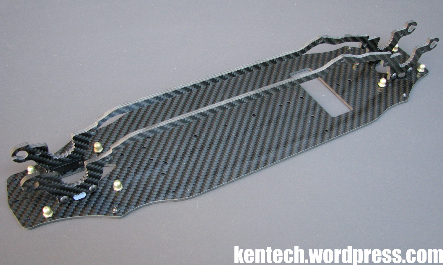
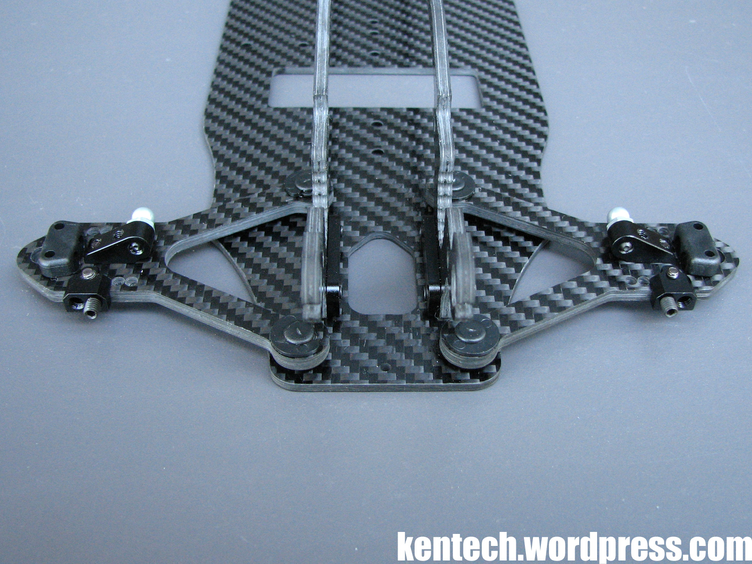
With the side plates added, this is what the chassis looks like.
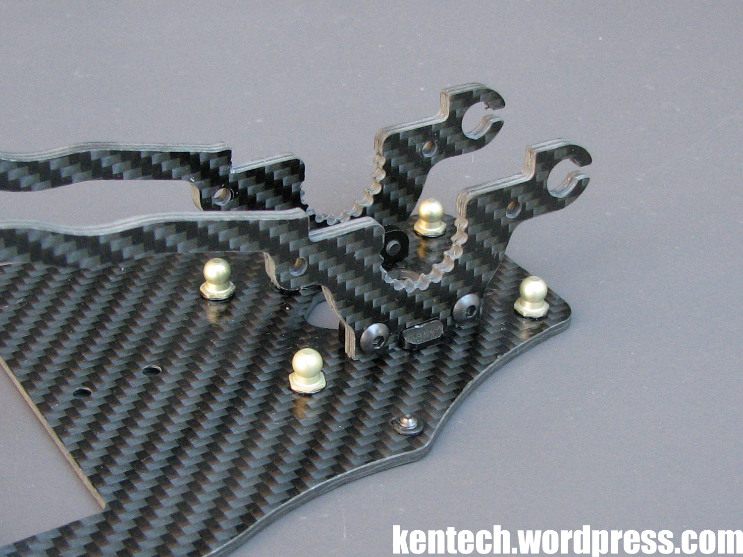
A closer look at where the side plates attaches to the side plate mounts. 3x6mm screws are used, and as I wrote above the fit is very good. In the above picture you can see where the mount keys into the side plate.
From behind you can see how slim the construction with the side plate mounts really is.
Next it is on to the suspension.
First let’s take a quick look at the suspension arms, with all four exactly the same. These are again made from the 3.0mm thick carbon material, and weigh 4.0g per arm in this bare form. The suspension is obviously very different, but the center to center length is around 53mm (if my measurements are correct) which is not far off your ‘normal’ TC.
The suspension arms attached to the GZ1 chassis, here the rear arms. All the parts are the same both front and rear, but the damper mounts are attached in different positions.
Again the rear arms with all mounting hardware seen in the picture above.
The “arm ball cup” is made of plastic (again an Awesomatix part) while the damper mount and roll bar mount is made from black anodised aluminum. These parts follow the same line as the rest of the car, and are very slim and light. The damper mounts offer two holes, while the arms offer four holes for these mounts. All these parts are mounted to the carbon arms with small/light 2.5x6mm screws.
To mount the arms to the chassis, wishbone inserts go over the suspension balls, and the arms then slide over the wishbone inserts, while all is secured by large plastic c-clips. Mounted, the arms move freely but without any major play. Feels good..
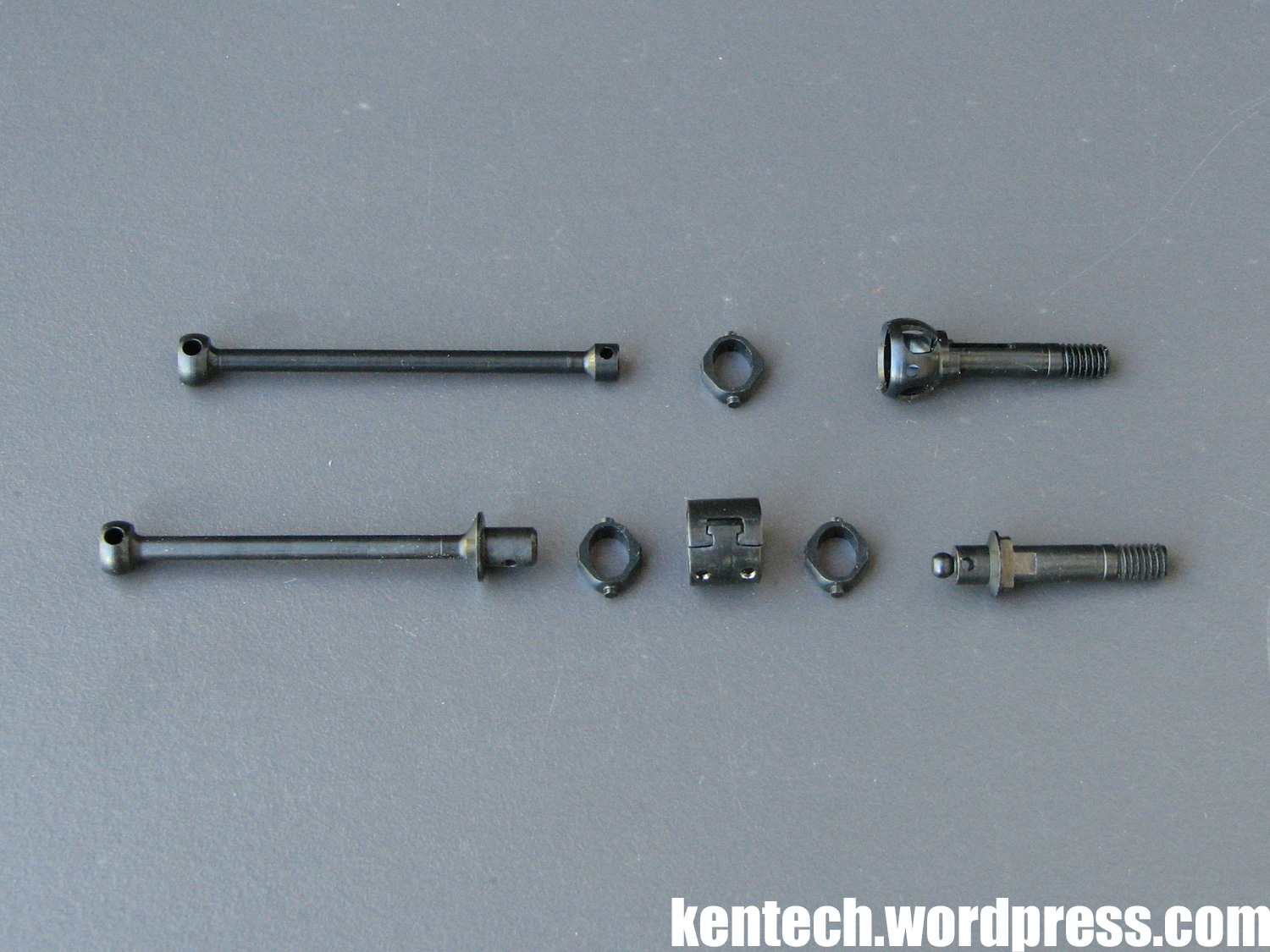
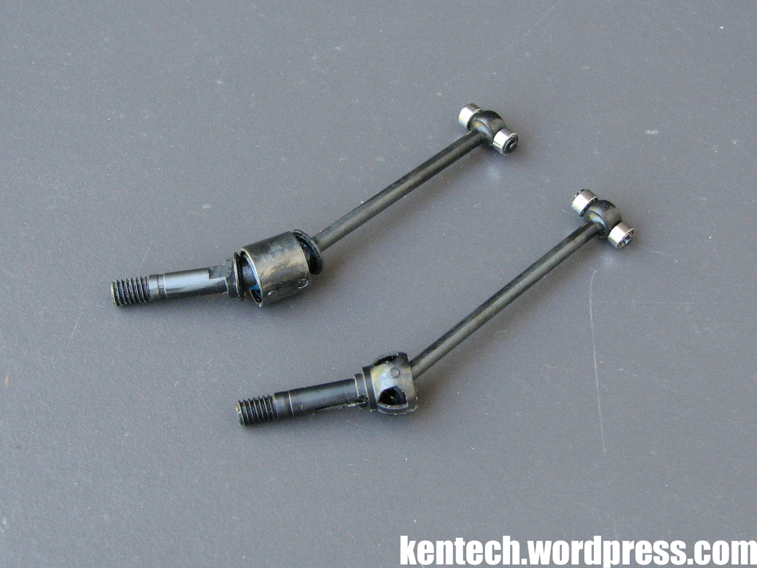
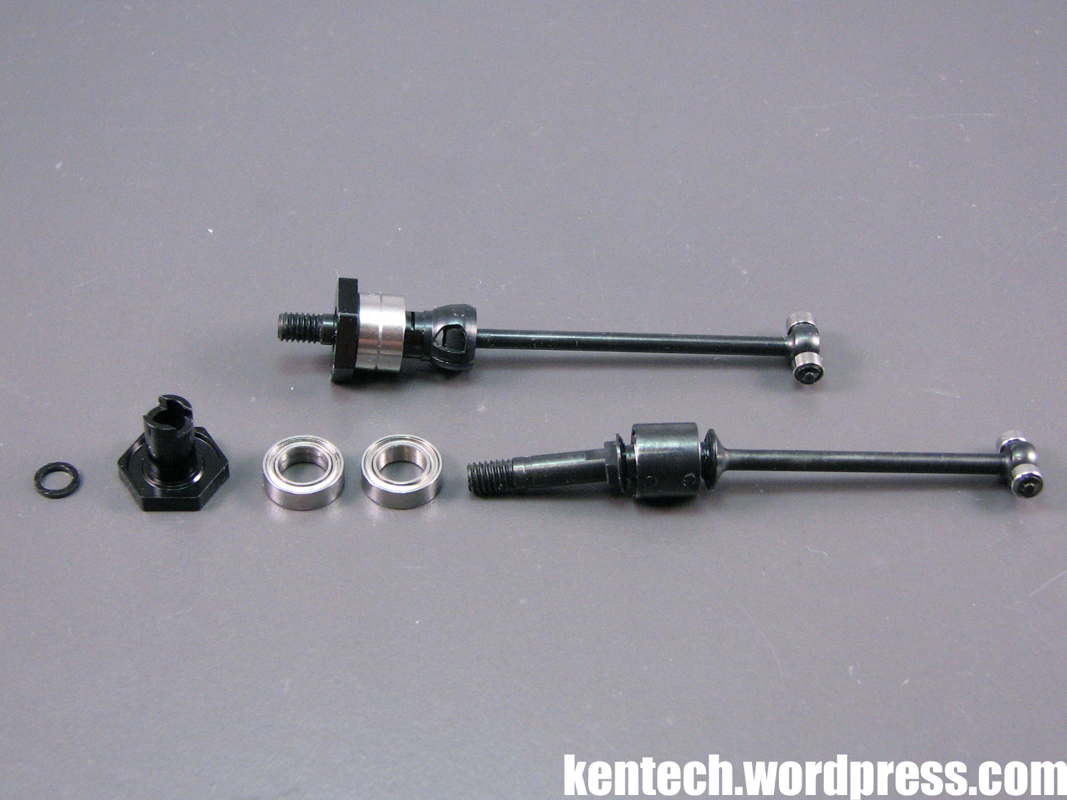
Bag B consists of the front and rear driveshafts.
For the front, a pair of double-joint driveshafts are included, while there are single-joint driveshafts for the rear of the car. Again, these are complete Awesomatix items, which means their construction is very different from what you find on other touring cars.
The plus side is that you get some super lightweight and well performing steel driveshafts, while on the minus side they can be a bit of a pain to assemble, especially the double-joint front driveshafts.
A complete double-joint driveshaft weighs a mere 6.0g, while the single-joint version is 4.1g.
As on the Awesomatix, super small bearings are used where the driveshaft connects to the diff outdrive.
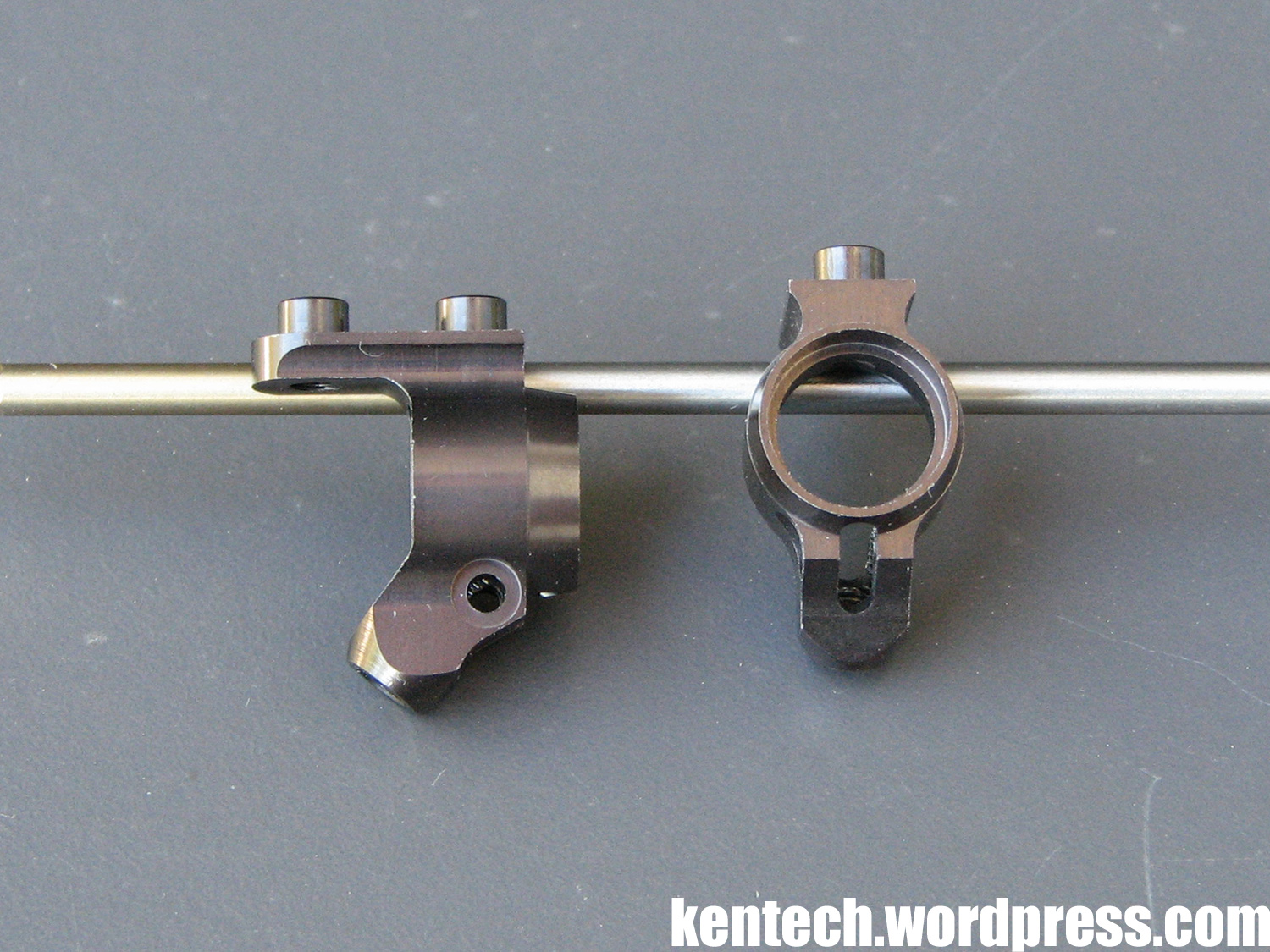
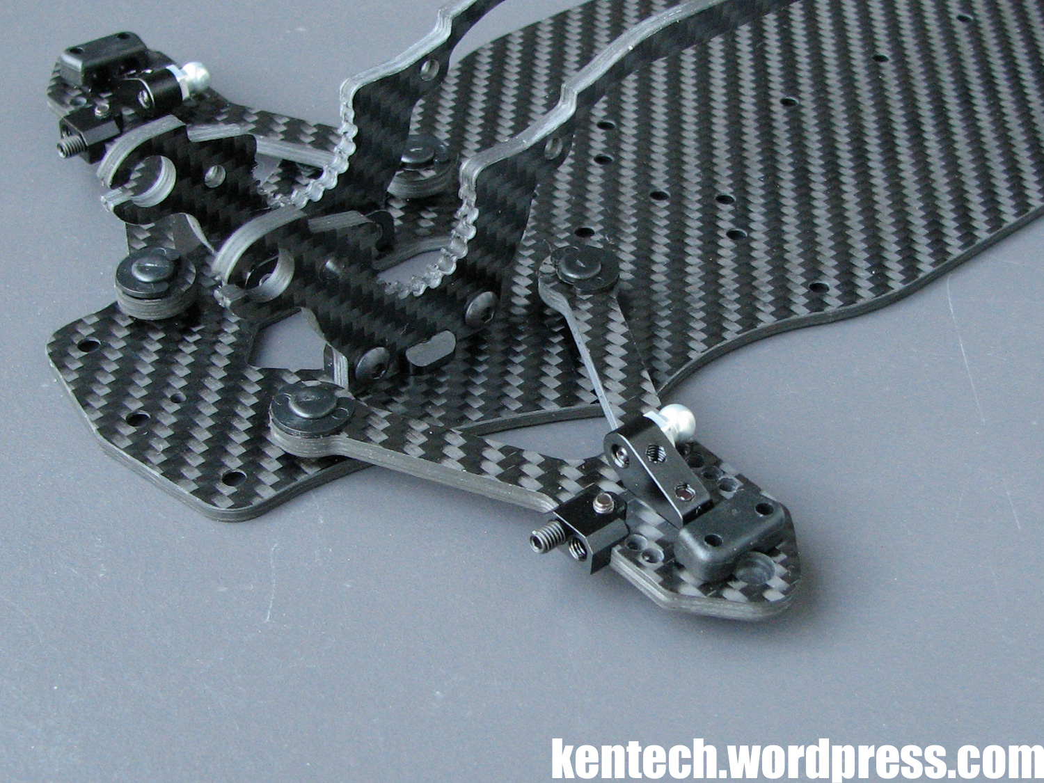
Next on to the uprights, another favourite part for me on this car. Made our of aluminium, they are again super slim and small parts, with the same part used at all four corners.
The weight of one – just 2.2g!
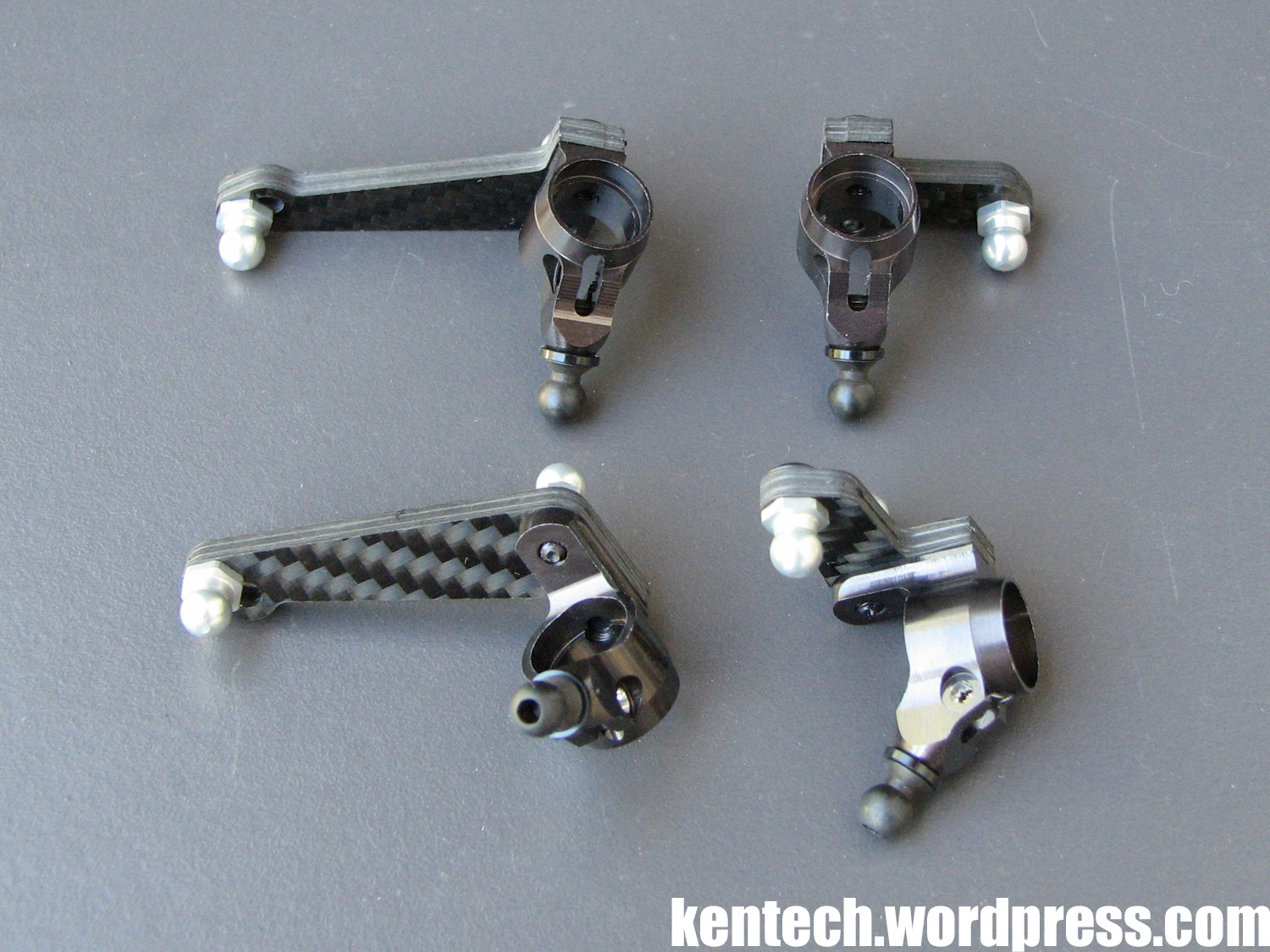
While the upright itself is the same front and rear, the carbon arms attached to it are obviously different. These carbon arms use 3.0mm thick material.
The driveshafts / wheel axles / bearings go together like this.
As can be seen in the picture above, on the inner end of the wheel axle part of the driveshaft there are two flat spots, with corresponding flat spots on the inner end of the alu wheel axle / wheel hex part. The wheel bearings, which due to this construction have the unusual size of 6x10x3mm, are inserted into the upright. Then the wheel axle is inserted from the outside, while the driveshaft is inserted from the inside, going inside the wheel axle, finally lining up the flat spots and securing everything with the small lock ring seen above as well.
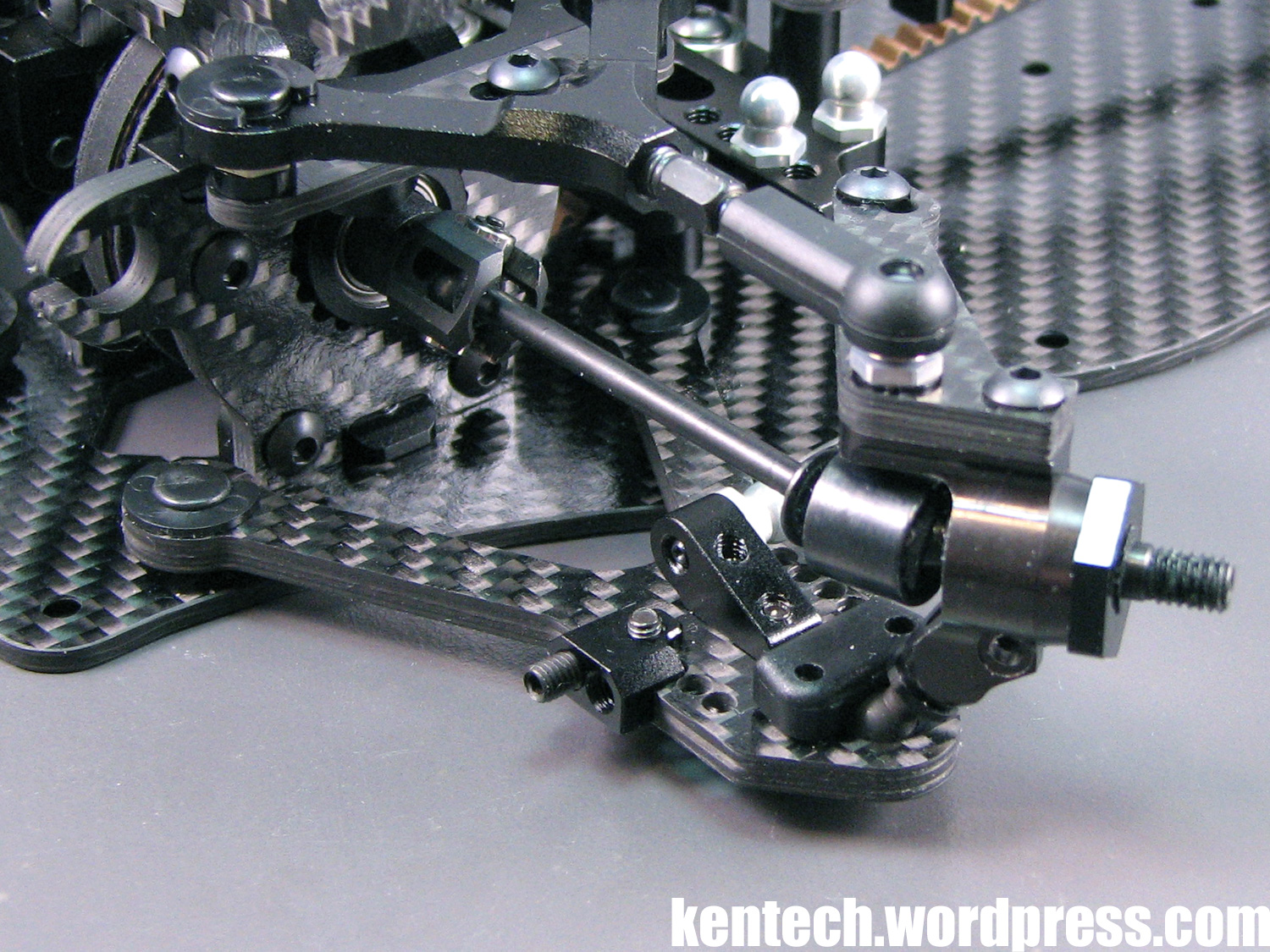
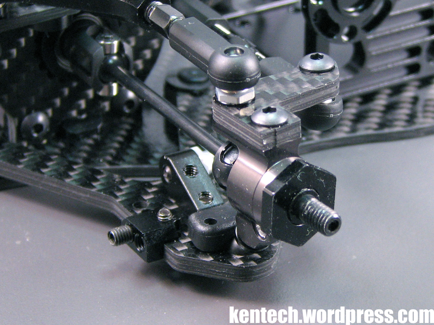
Front driveshaft / upright assembled and fitted to the car.
The plastic holder which keep the upright attached at the lower end (“arm ball cup” in the parts list) can be adjusted by tightening the screws holding it, allowing you to adjust it so it’s tight for no play, but still free.
Rear upright fitted with driveshaft and wheel axle / hex in place. Here you can see the small locking ring in the center of the hex securing the axle assembly. You can also see that the driveshaft is hollow at the outer end – one reason for their lightness.
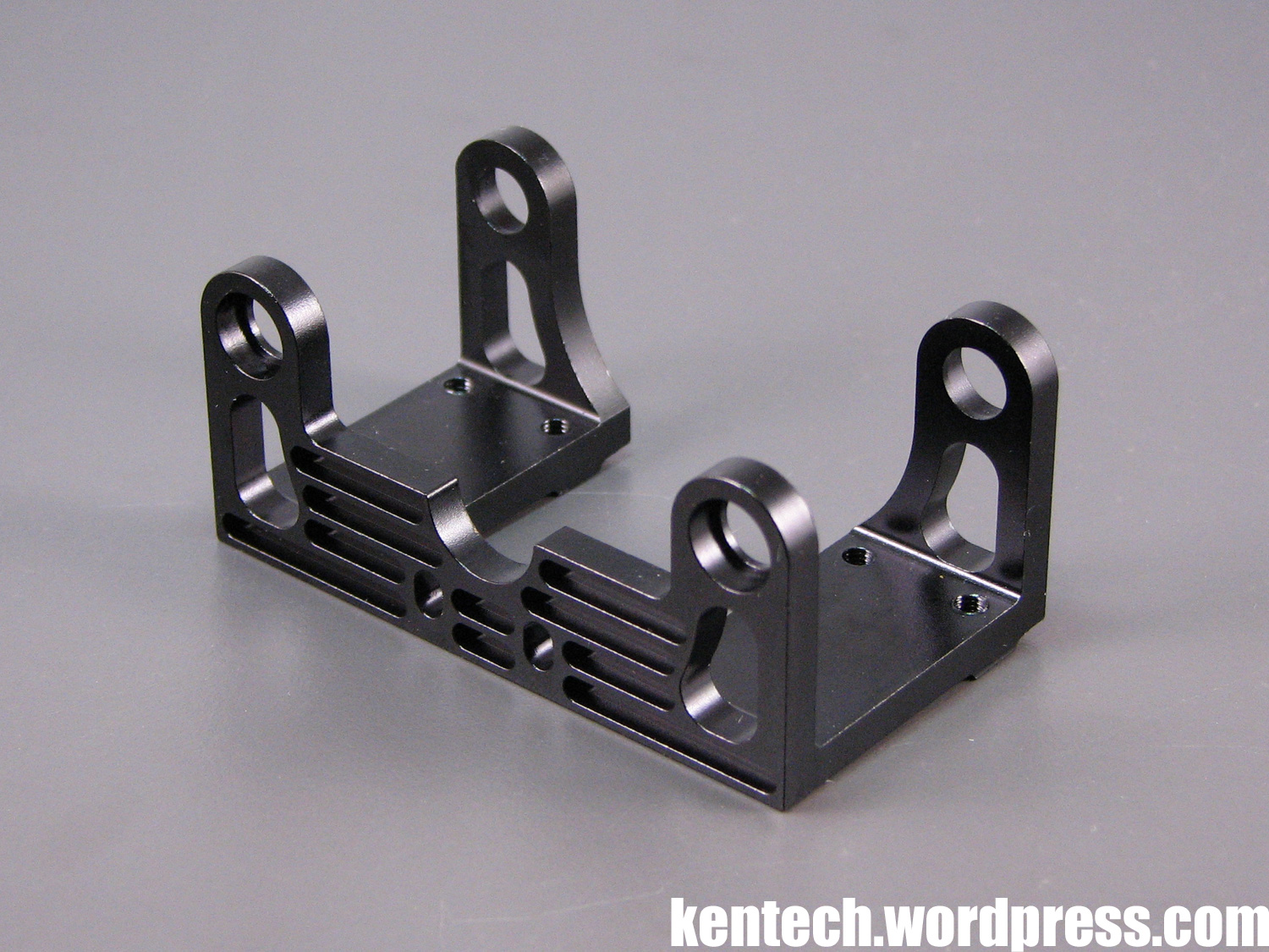
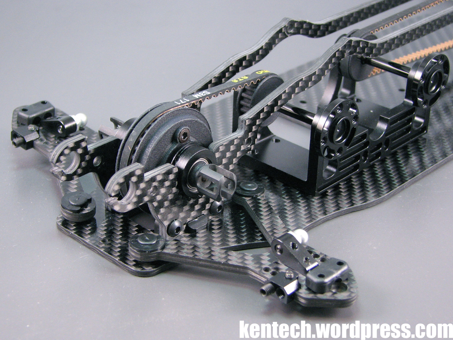
Bag D means the motor mount and accessories.
The motor mount, one-piece machined black anodised aluminium, is quite a substantial part on the GZ1. The motor mount is attached to the chassis with four screws, all on the centrerline of the chassis.
As can be seen above, the motor mount only touches the chassis around the four screws along the centerline, while the rest again ‘floats’ above it to keep any negative effects on flex to a minimum.
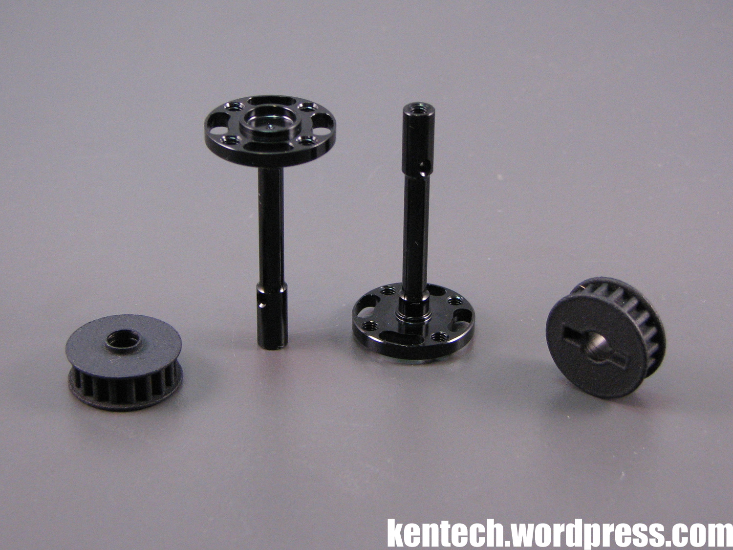
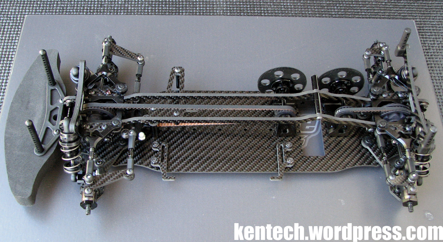
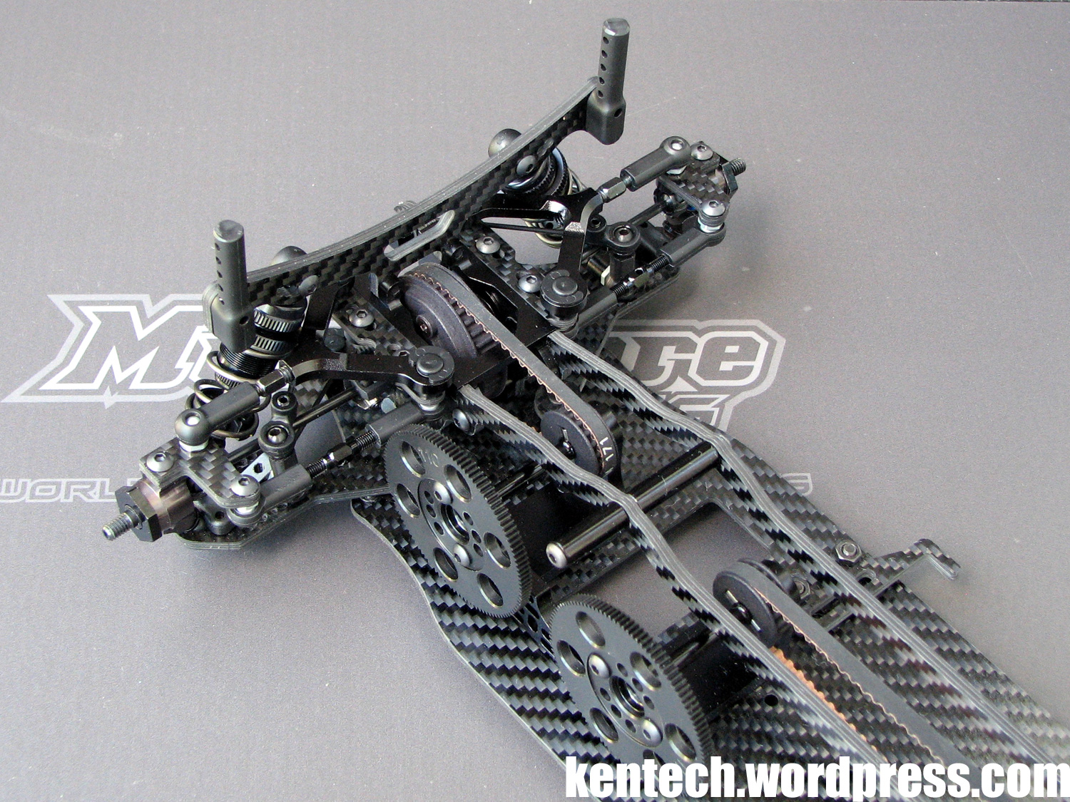
One of the unique features on this car, and perhaps the one that stands out the most, is that it has two spur gears, and therefore two center shafts. Obviously one pulley for the front shaft and belt, and one for the rear shaft and belt.
The shafts are again one-piece and aluminium, and super light at just over 2 grams! The pulleys are 18T and specific for the GZ1, and like the diff case and spool which you will see later, appear to be produced with some sort of rapid prototyping / 3D printing method.
Pins secure the pulleys to the shafts, while 0.1mm shims are included to shim the centershafts. The shafts run on 5x8mm bearings.
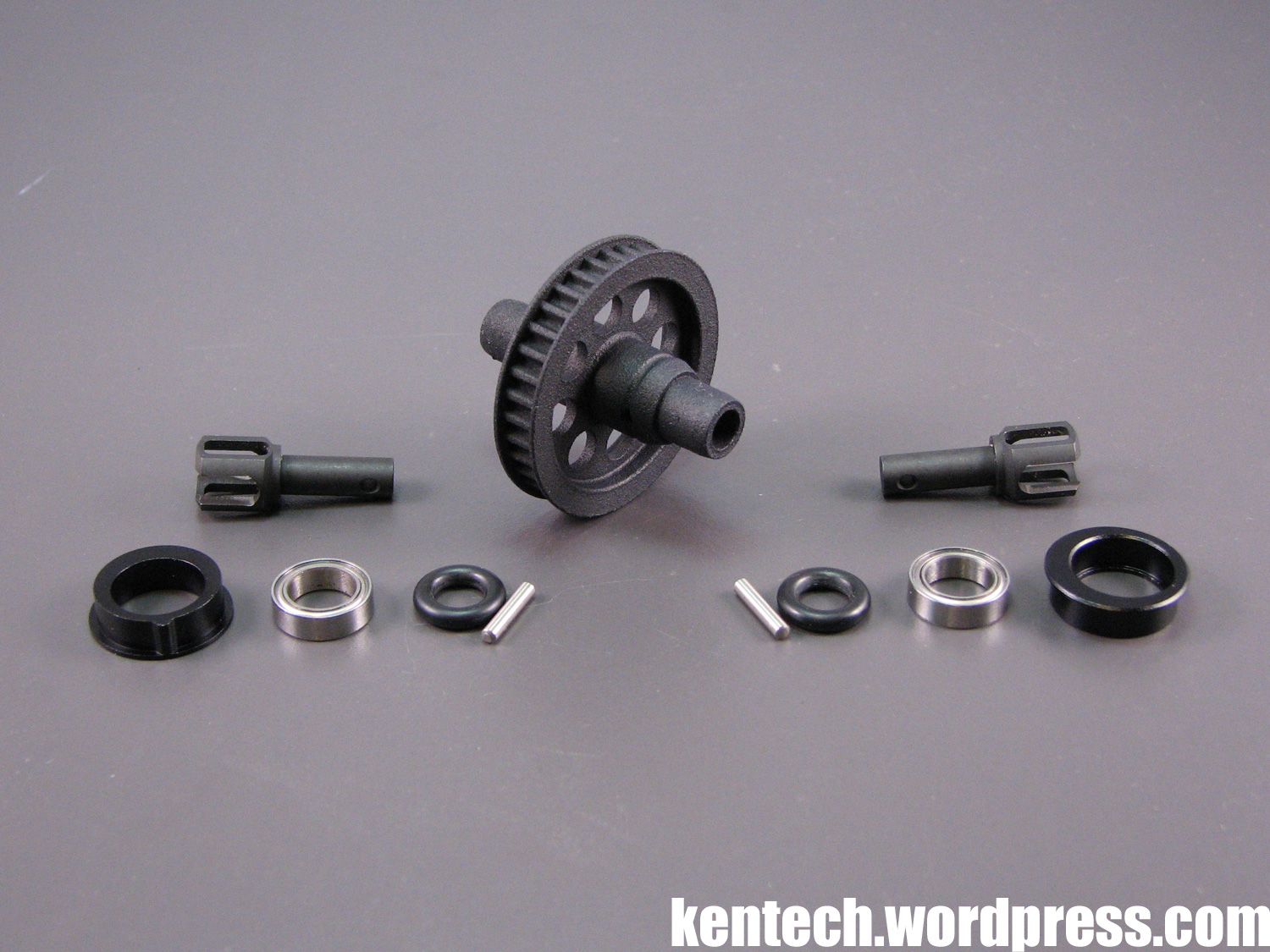
For the front, a solid axle (spool) is included. As I already mentioned, this is made by a similar material to the center pulleys, which can be seen by the surface finish of it. It does not look as pretty as a well moulded or machined part, but for a small-scale startup racing car manufacturer it makes perfect sense. It is fairly small in diameter, as it is 35T.
The outdrives are steel, and actually the same as the gear diff outdrives. A good idea as it cuts down on the different spare parts. They are held in place by pins, which in turn are held by thick black o-rings. When you assemble it, make sure to do it in the right order – first thread the o-ring partly onto the spool, then put on the bearings, then the outdrives and pins, and finally slide the o-rings into the groove.
The bearing eccentrics are machined aluminium, while the bearings are not what you could call the normal size (10×15), but instead 8x12mm.
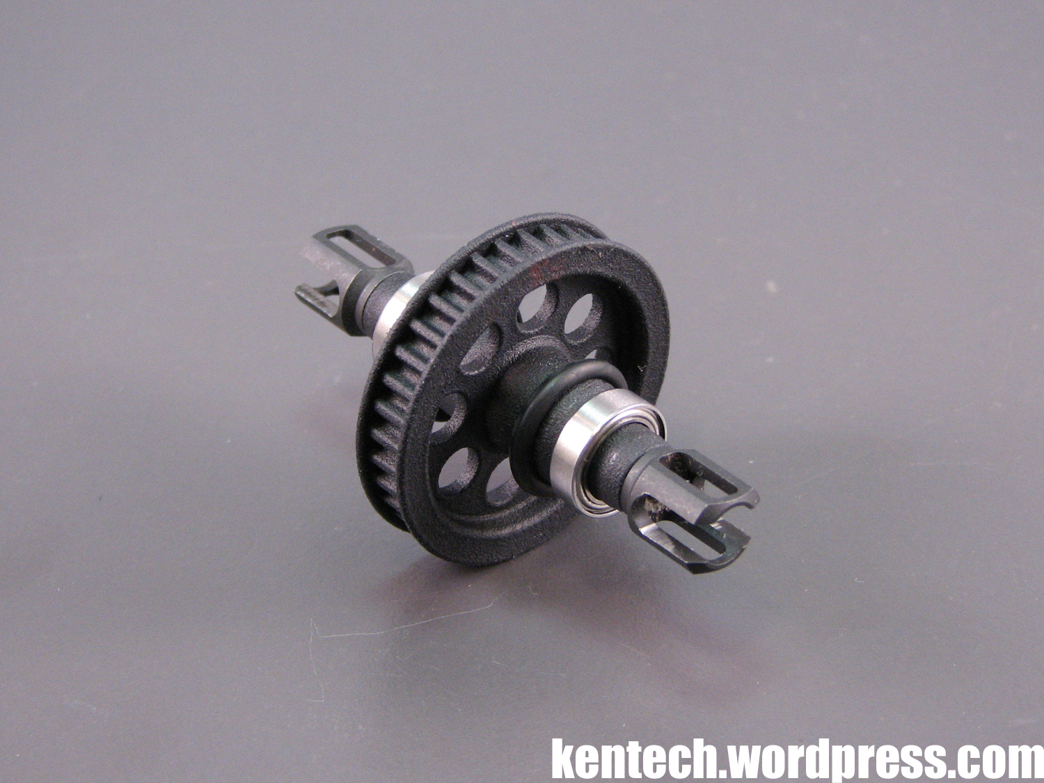
All assembled, the spool looks like this.
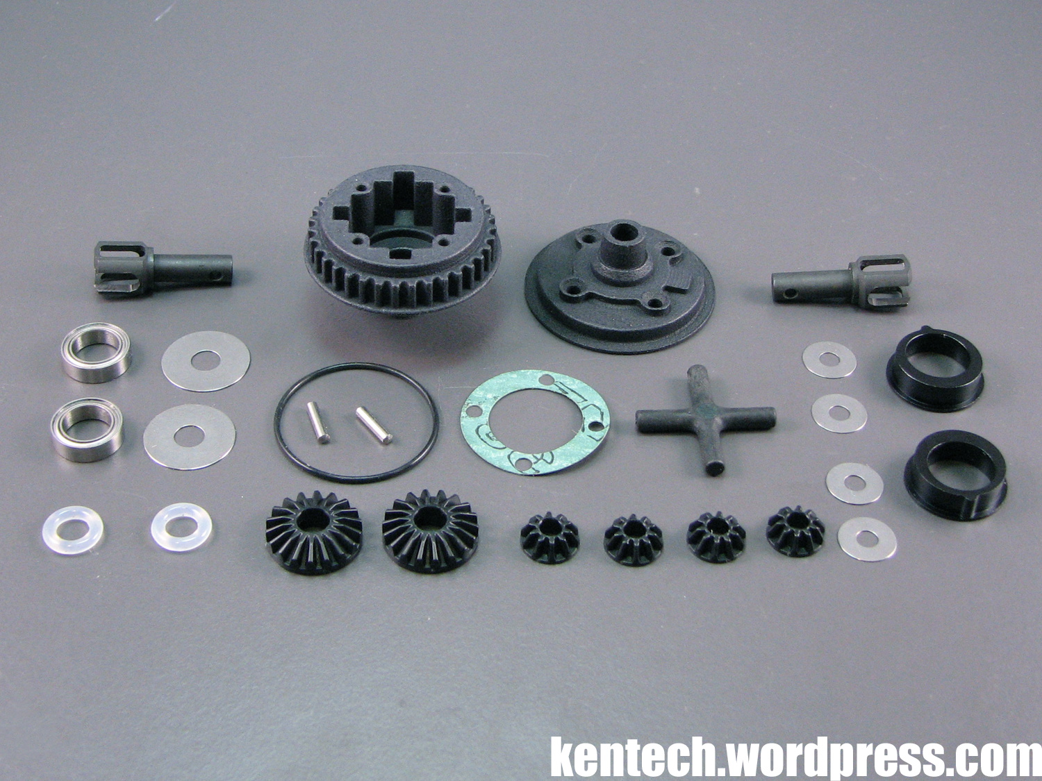
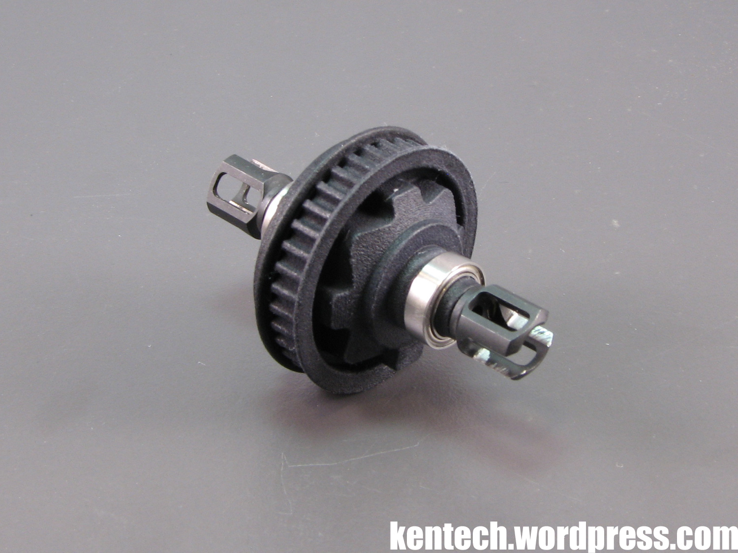
For the gear diff, the diff housing and the outdrives are specific GZ1 parts.
All the internals are however straight from Xray’s T4 gear diff, which should be seen as a good choice and decision by Gizmo. The Xray diff is well known to be among the best, and it would have made no sense at this stage to make all of these parts. Gear diff performance is very impostant in today’s electric touring cars, and by using these parts Gizmo can more or less guarantee a well working one.
A small bottle of 3000 weight diff oil is included and should be a good starting point.
The bearings are obviously the same 8x12mm as at the front.
The diff went together without any issues and I expect it to perform well. Testing will have to confirm how well it works though.
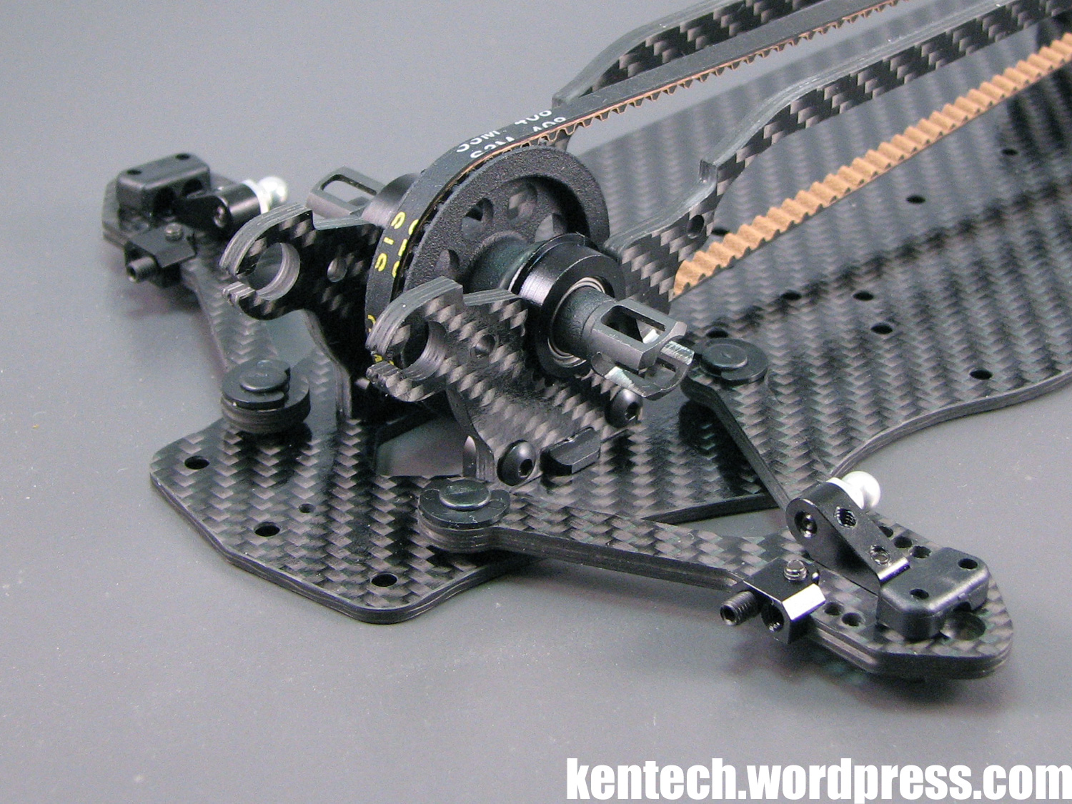
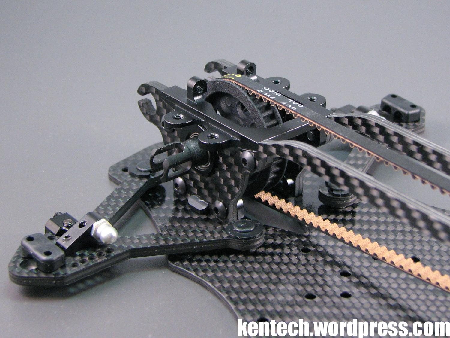
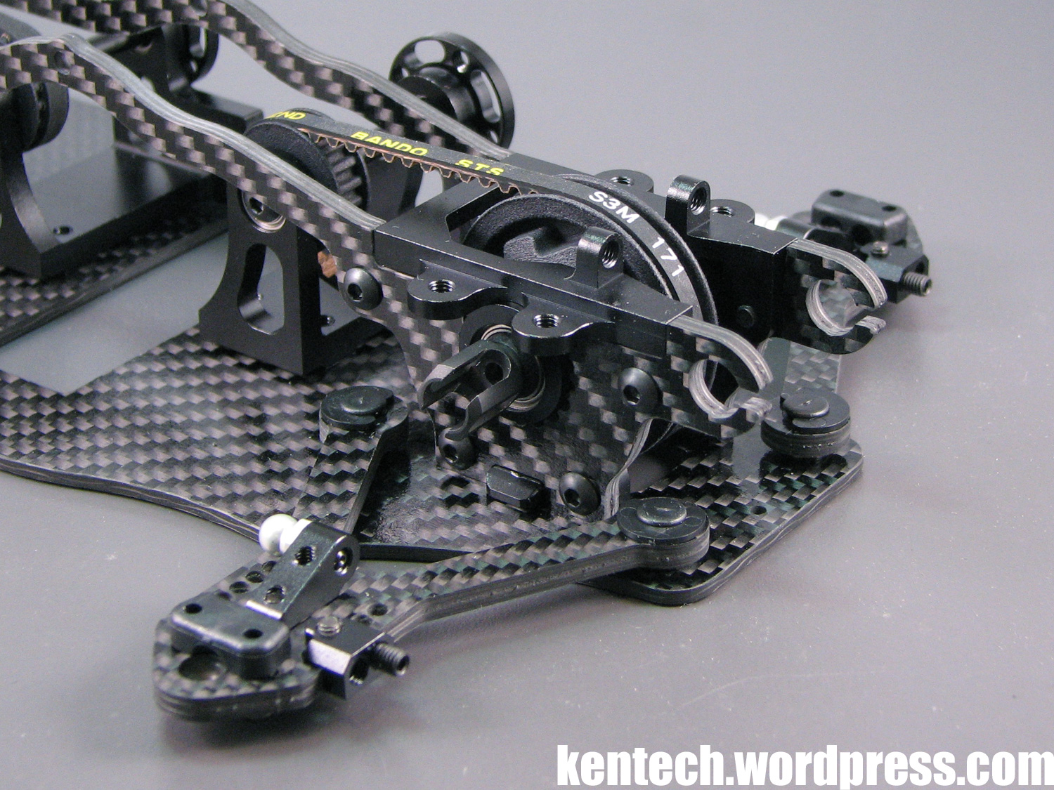
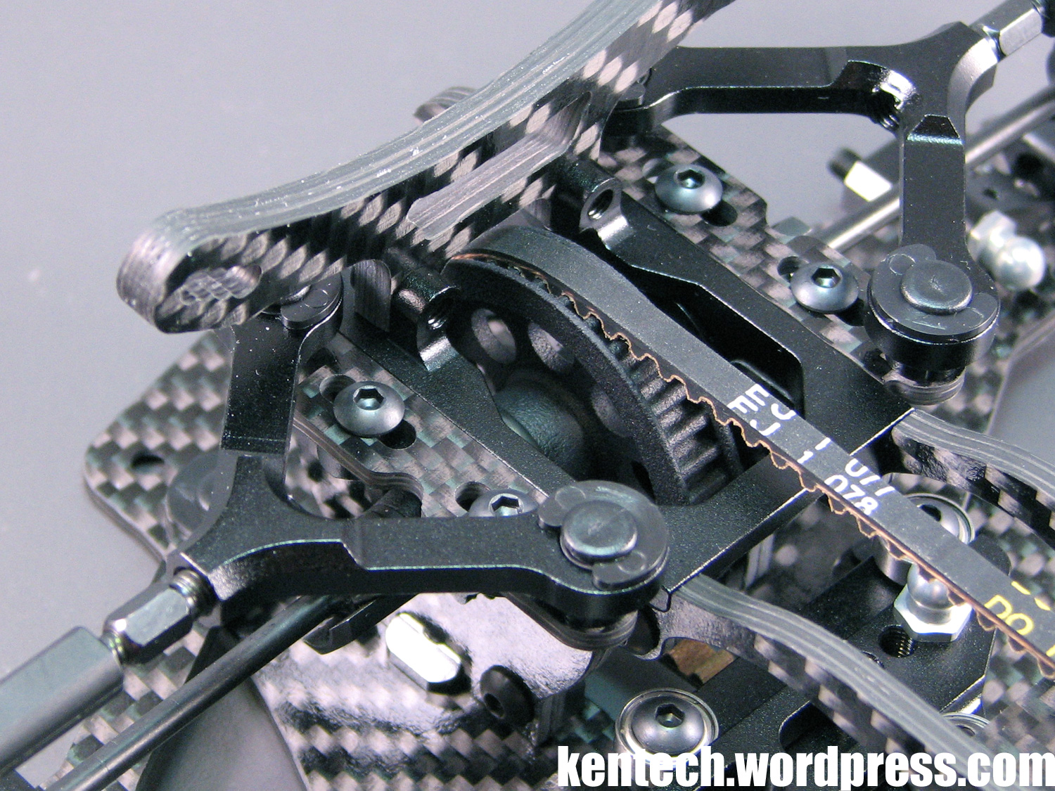
Front spool in place. I found the suggested belt tension to be quite tight, so I loosened it by one step as a starting point. Everything fits well and it feels a bit different with the carbon fibre side plates, after many many years of fitting spools and diffs to aluminium bulkheads.
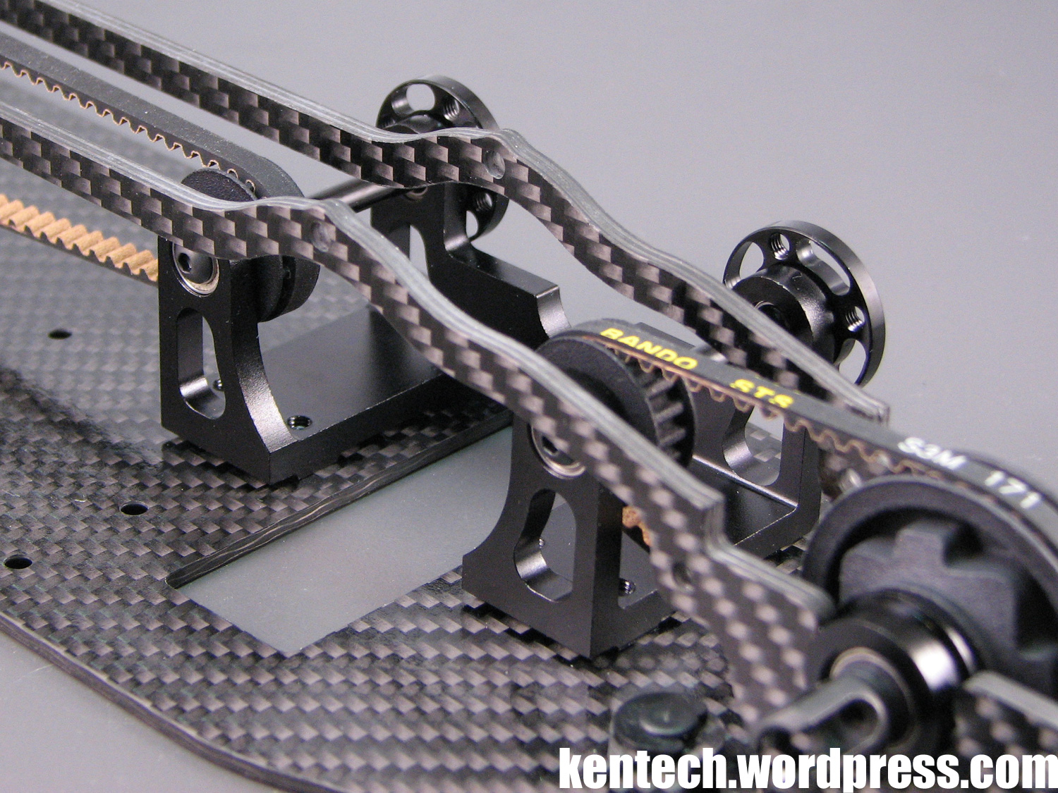
The front belt is 408mm, or 136T, so a bit shorter due to the axle and pulley for it being in front of the motor. The belt type is the industry standard S3M, with the belts used made by Bando.
The rear belt is 171mm, or 57T. Again at the rear I adjusted the belt one step looser compared to what’s suggested in the manual.
Also seen in this picture the motor mount in place together with the two centershafts.
Another view of the motor mount, where you clearly see it floating above the chassis.
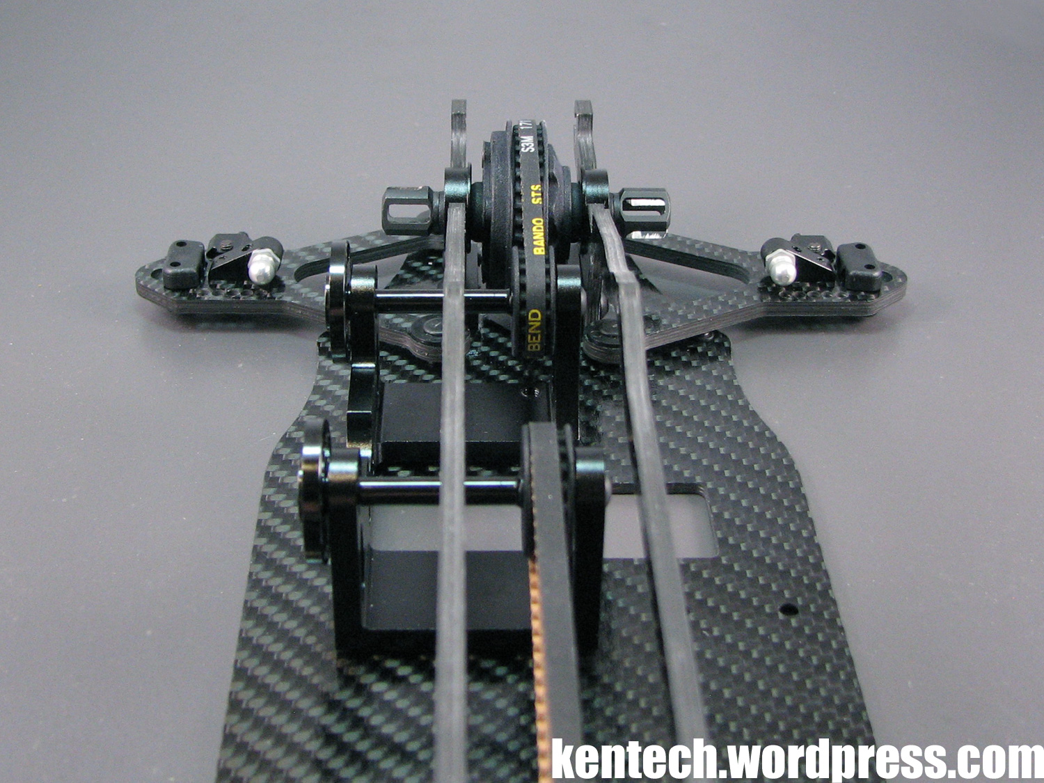
The front and rear belts and all pulleys are on the centerline of the car, with the separate shafts for front and rear drive making this possible. This places the torque forces on the centerline which should help handling.
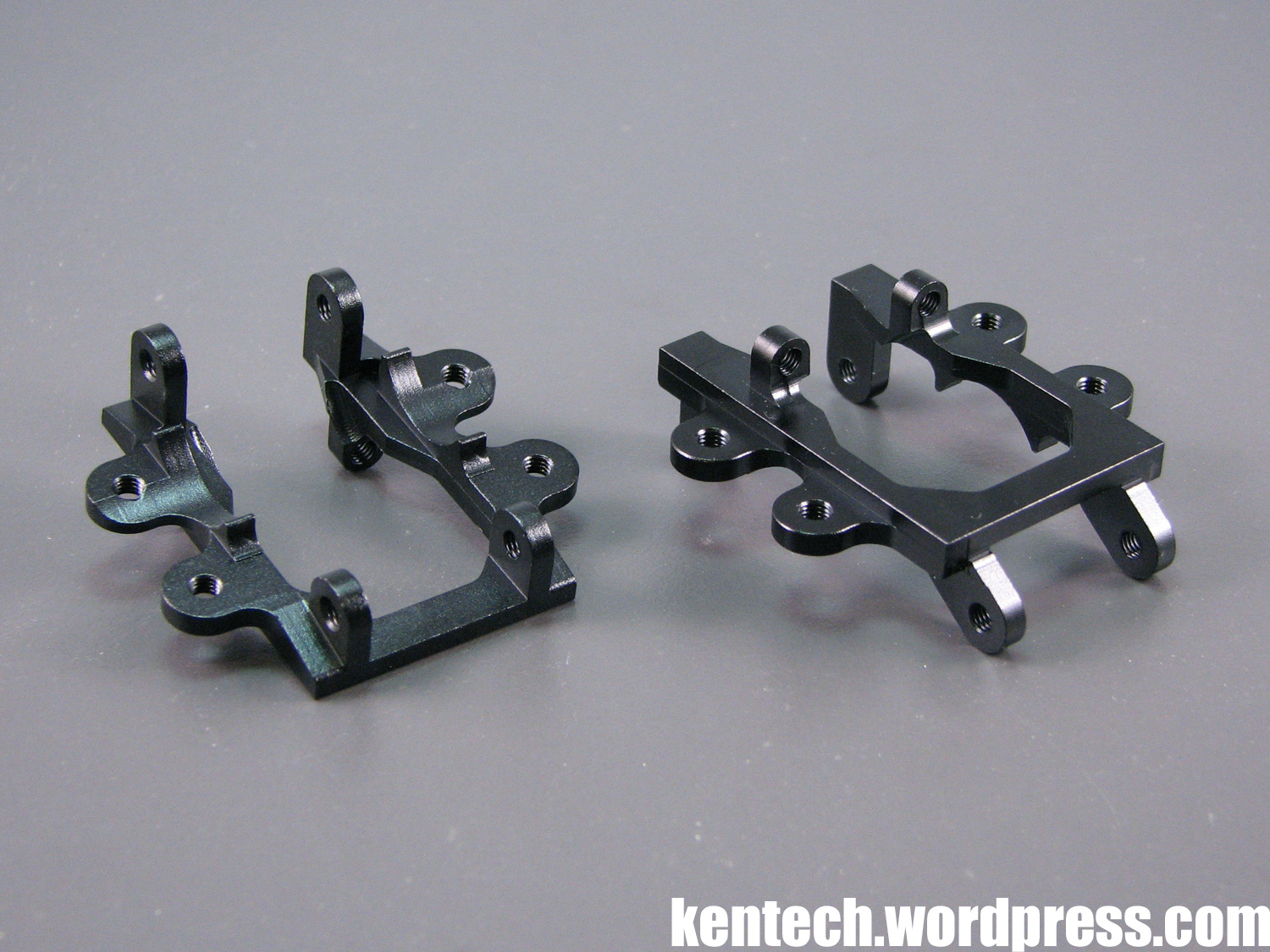
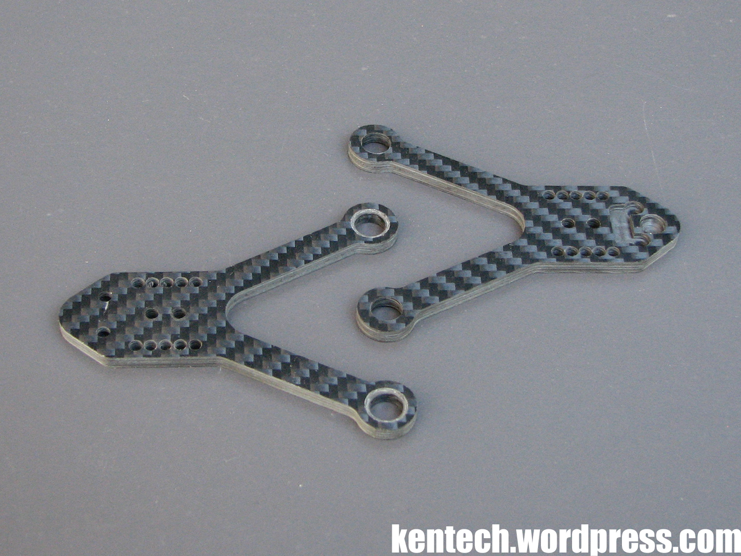
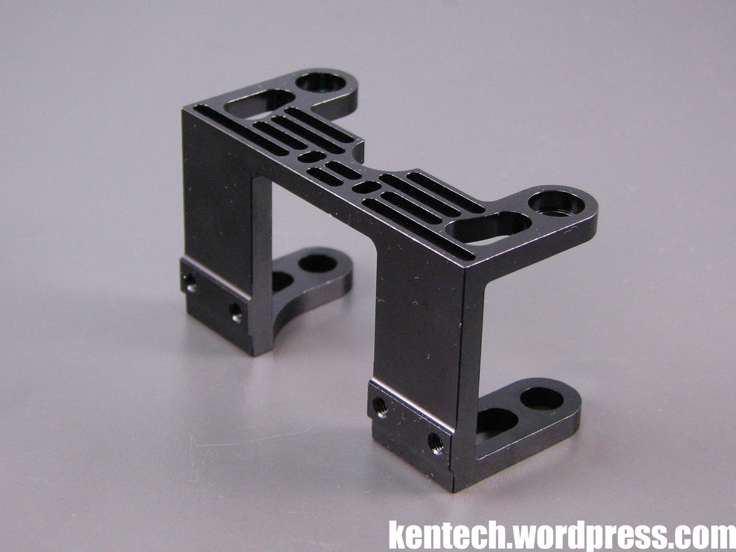
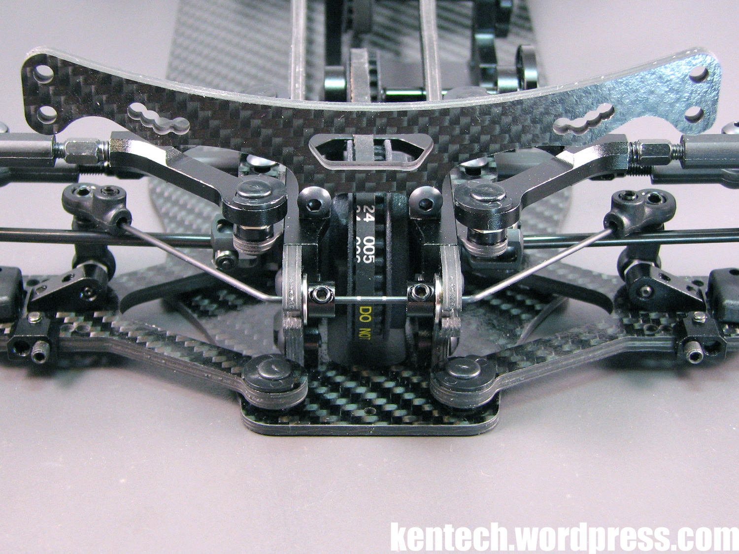
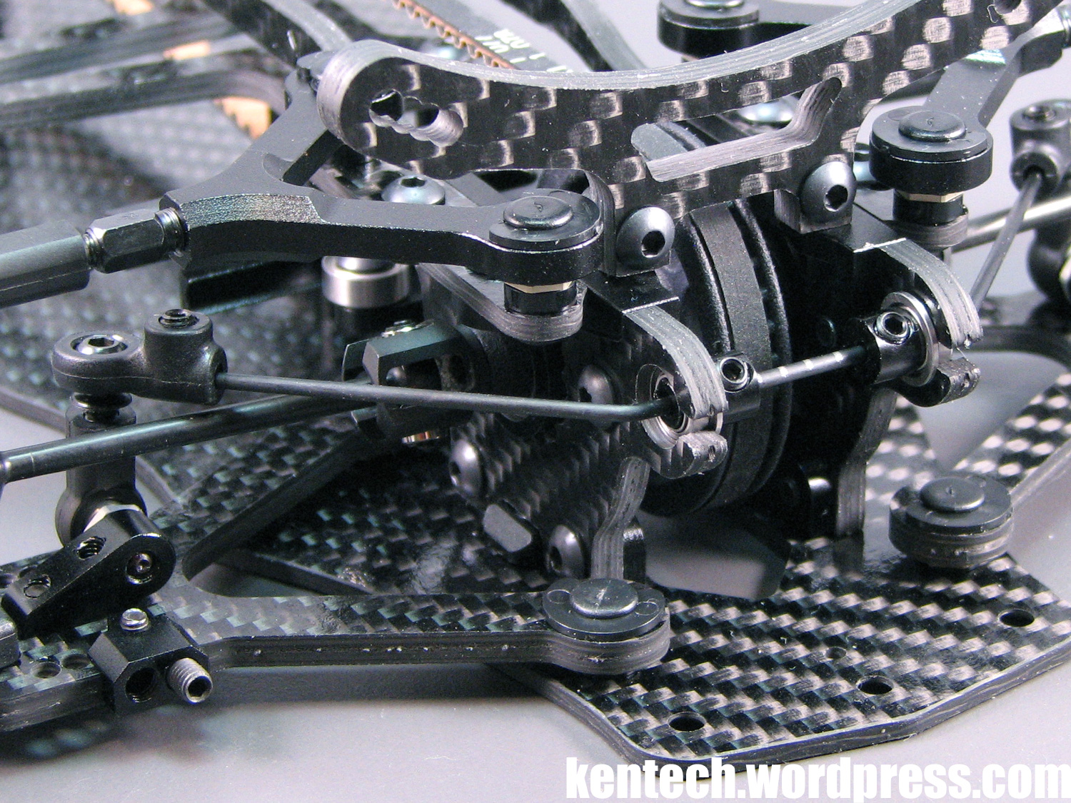
As we move onto bag F, the first step is the front and rear upper mounts. Both are beautiful single-piece aluminium parts. The front and rear parts are different as you can see in the picture above. On the left side, the front mount is turned upside down for this picture, to give you a better idea of the parts, while on the right side you find the rear mount.
The mounts are secured with two screws on each side, one at the front of the part and one at the rear. Obviously these parts hold the diff/spool and their eccentric adjusters in place. The mounts, both front and rear, really keys into place and make the “gearboxes”, if you like, really solid and precice.
Everything here fits really well together, and this construction is a real stand-out feature of the GZ1.
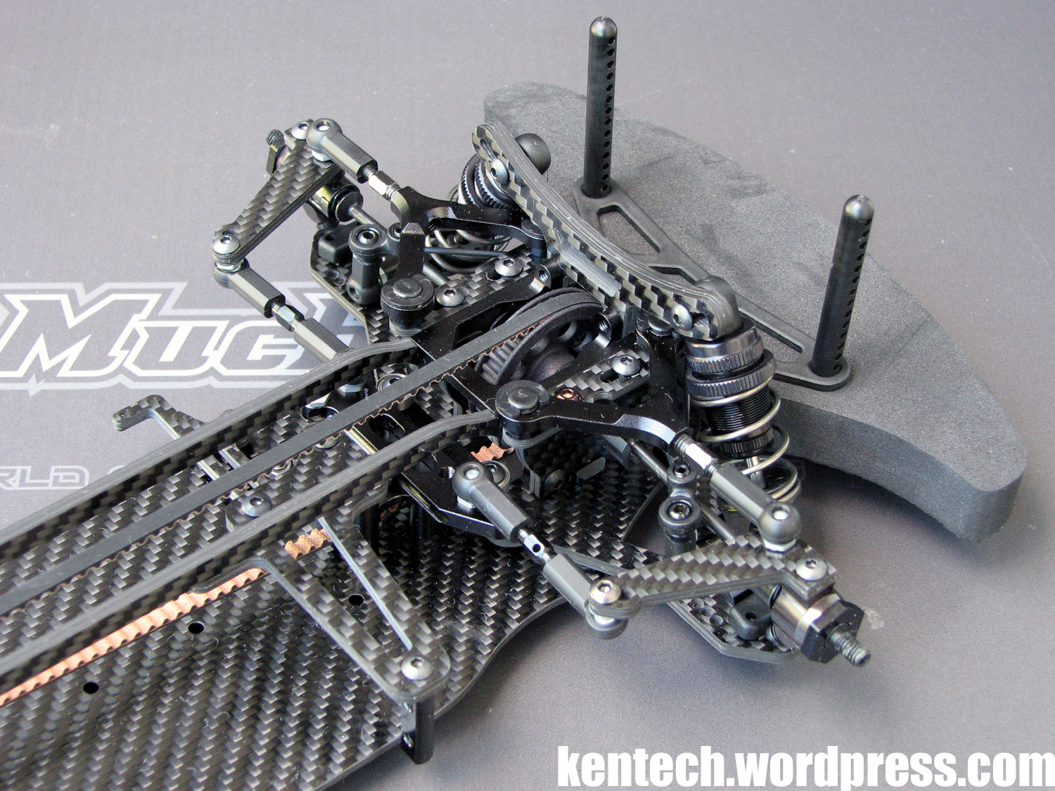
Personally, I really like the slim theme of the car, seen here on the super small mounts for the damper towers.
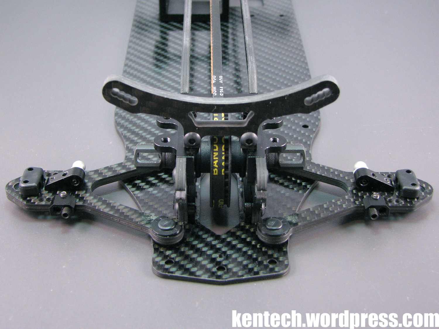
The front damper tower is a massive 4.0mm thick, and offers four different mounting positions.
When fastening the tower to the mount, I hade to sand down the bottom of the tower just slightly. Obviously it has been designed such that the alu mount will support the tower, and therefore you want it to be exact. It was just a little bit too tight though, but just a slight sanding made it perfect.
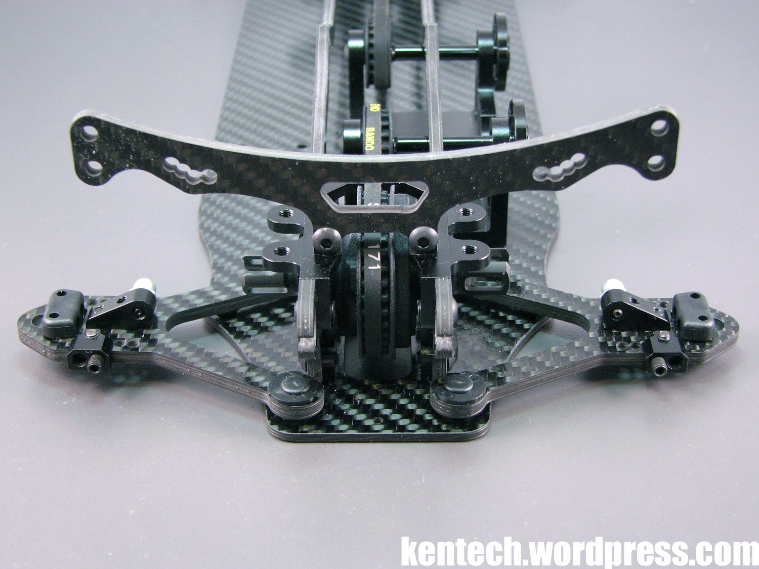
The rear damper tower is 3.0mm, so 1mm thinner than the front one. Again you find four mounting positions for the rear dampers. I also had to sand the same amount from the bottom of the rear tower to make it fit perfect.
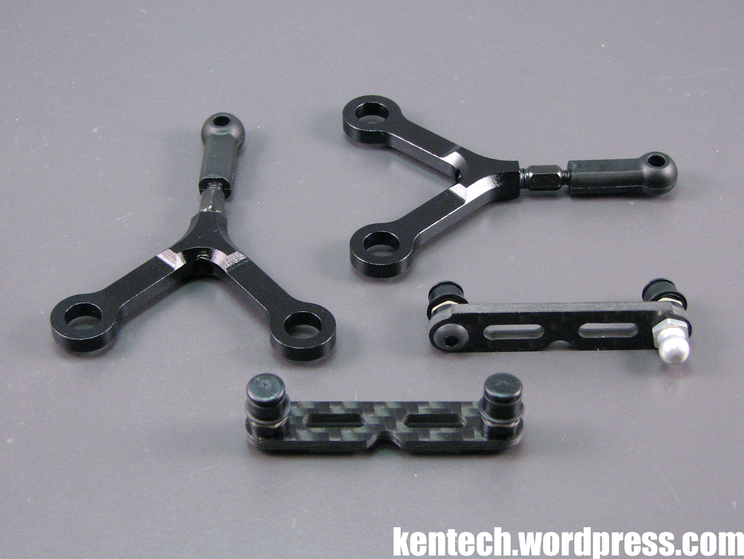
Next up, the upper arms and caster plates.
The triangle upper wishbone is made out of aluminium, with a steel turnbuckle threaded into it, and a plastic ball joint (which looks like an Xray part) at the at the outer end. The turnbuckle is thicker at the end which goes into the alu upper arm, with thread lock already applied from the factory. The alu triangle weighs 3.1g, while the upper arm fully assembled weighs 5.3g.
The caster plates, which the upper arms attach to, are made of 2.0mm carbon fibre. Roll centre adjustments can be made with spacers under the balls here, with 2mm spacers front and rear the initial manual setup. The same wishbone inserts used for the lower arms also goes over these balls, and the upper arm then slides over these, while everything is secured by the same large plastic clips.
On the caster plate to the right in the picture above you can see that at one end a ball is also attached to the bottom of the plate, both therefore secured by a long grub screw. This is used for the toe link at the rear of the car.
Caster is adjustable by sliding the caster plates, and therefore the upper arms, forward or rearward. Each plate is secured with a forward and a rearward screw, with the caster plate holes slotted. An easy way to adjust caster.
The setup, i.e. the caster plates, is exactly the same on all four corners of the car.
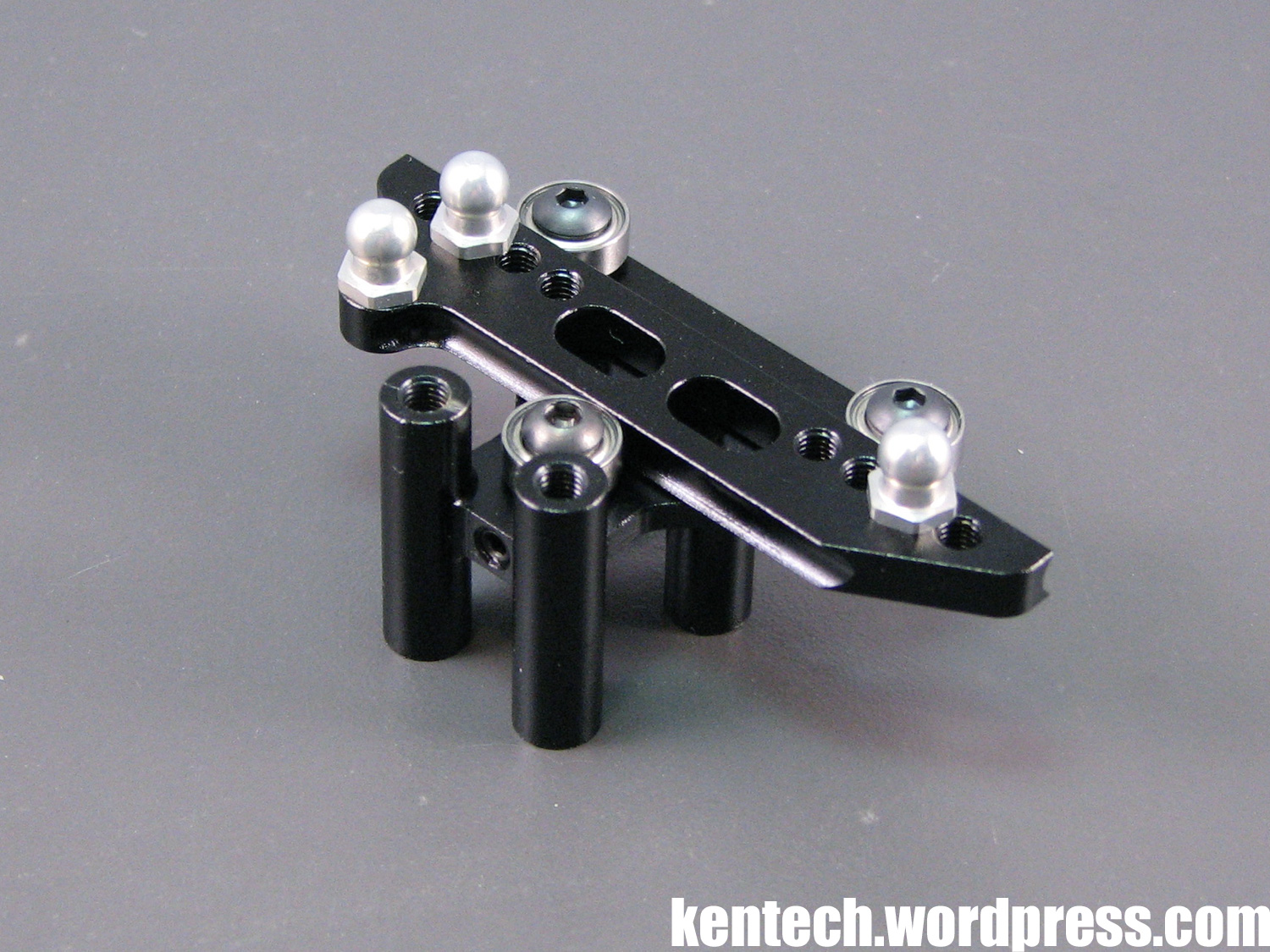
The GZ1 uses a steering rack instead of the more usual swingarm setup. Both the steering mount and rack is made from aluminium again, with three bearings supporting the sliding rack, which has multiple holes for different lengths of steering links.
A grub screw threaded from the rear of the steering mount lets you adjust how tight the rear bearing pushes against the rack, allowing you full control over the play/freeness of the steering rack.
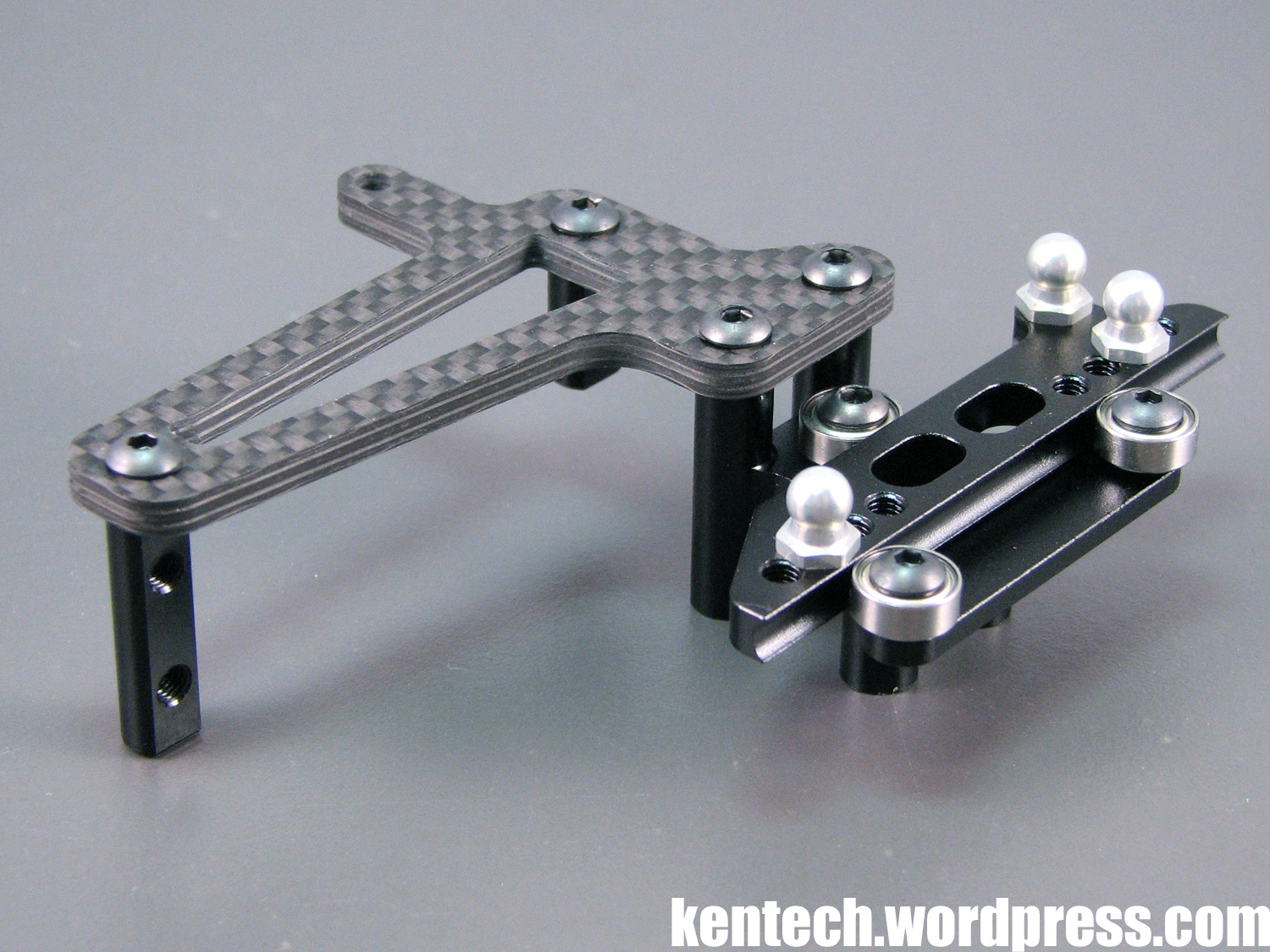
The servo plate attaches to the same steering mount, with a short inner servo mount for one screw (since the belt gets in the way for the lower screw), and a longer outer servo mount fastened to the servo plate to complete the floating servo mount.
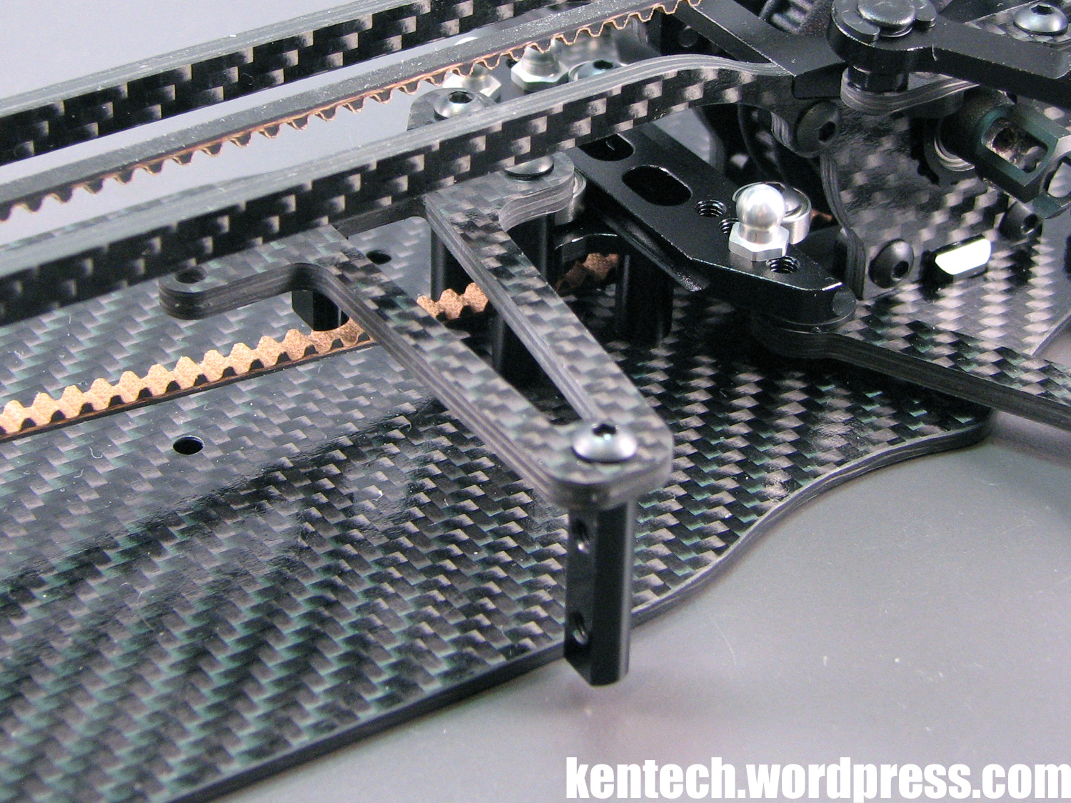
This complete steering assembly and servo mount is attached by four screws to the center of the chassis.
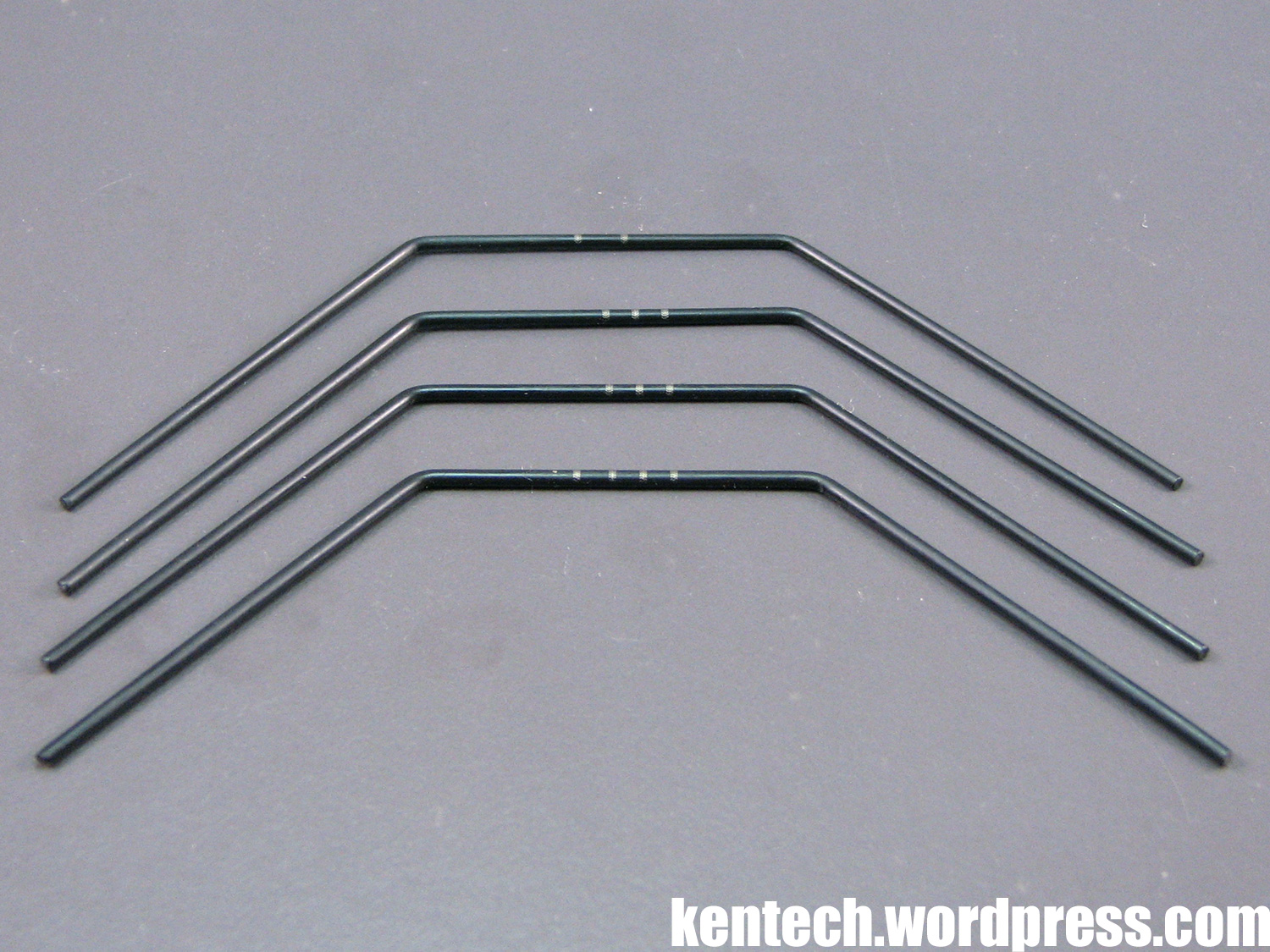
Bag H is the anti-roll bar bag. Four different bars are included with the kit; 1 pc of 1.2mm, 2pcs of 1.3mm, and 1 pc of 1.4mm roll bars. The bar type used front and rear are obviously the same, since the suspension and the mounts on the arms are all the same. The manual setup is a 1.2mm rear bar, and a 1.4mm front.
The roll bar setup is easy to assemble, easy to setup, and precise. The bars are held in place by flanged 4x7mm bearings and stoppers that fit into the bearing, making the roll bar assembly super free.
The roll bars attach to the arms via the roll bar mounts on the wishbones, through a ball cup with a threaded ball which allows easy tweaking of the roll bars to get the left and right side action perfectly equal.
At this point I jumped bag I and straight to bag J, basically since bag I includes the bumper, and I prefered to do the dampers before the bumper. Mostly because I need to think about taking pictures.
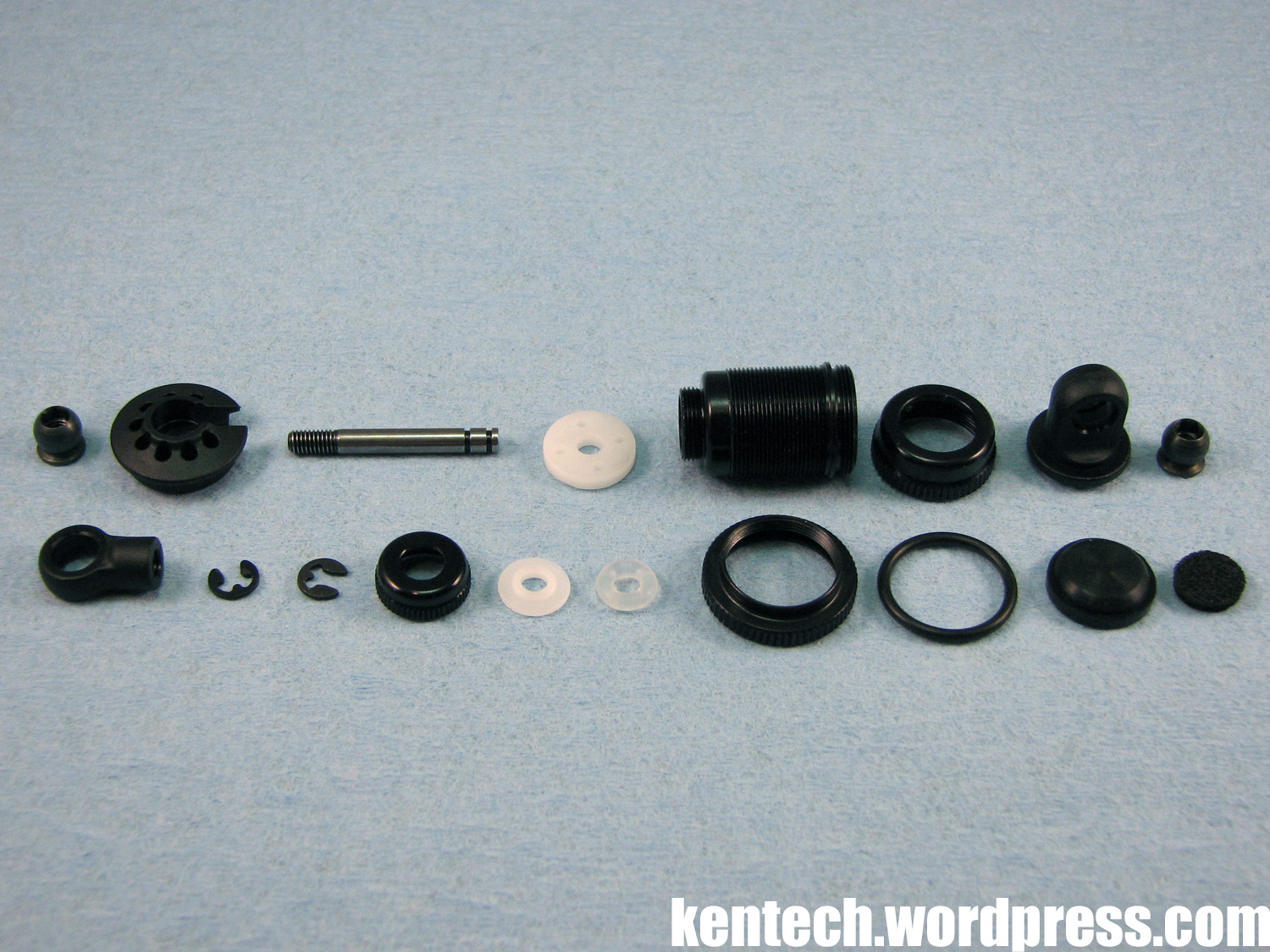
The dampers use Xray parts throughout, but they’re not the trendy super short dampers included with their T4. Instead you get slightly longer dampers to which you can fit normal length springs.
The parts for one damper assembly can be seen in the picture here above. A full set of pistons are included – built according to the manual the 4 x 1.1mm is used. The foam bits are included, but not in the damper build picture in the manual, so it’s your setup choice if you use them.
The inner diameter of the damper cylinder is 11.2mm, so with the length of them the oil capacity is quite large. A small bottle of 400 damper oil is included.
Regarding the choice of long dampers over short ones, here’s a quote from Gizmo:
“The shocks mounted on the GZ1 is a little longer then for example the ones mounted on the Xray T4, this is because a little longer shock body contains more oil for a better feeling. More important is that you can run a longer spring which generates more traction and more feeling”.
Personally I tend to agree with that comment from Gizmo.
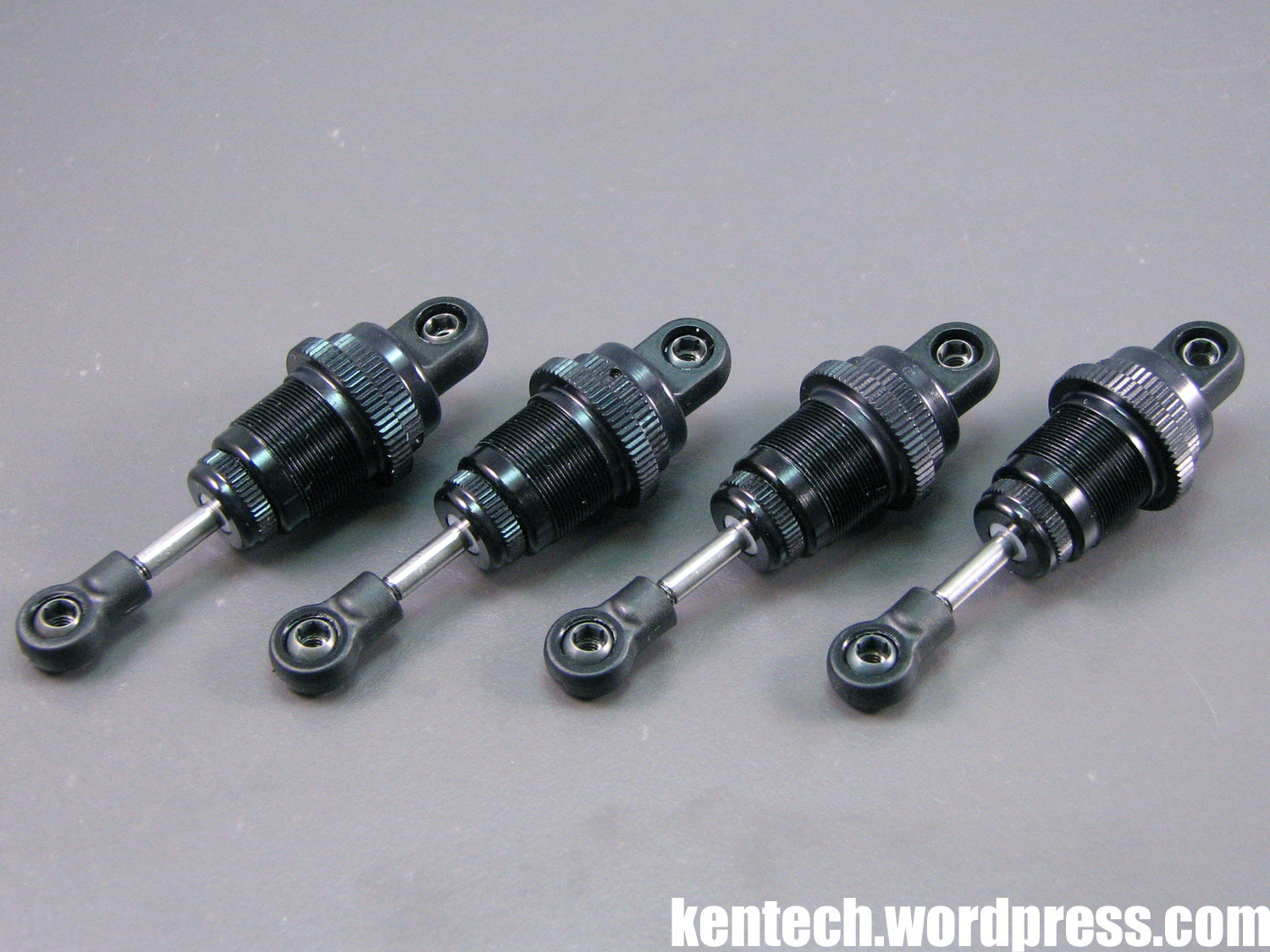
The four dampers all assembled. Being Xray dampers, there are no quality issues or problems assembling them, although I would perhaps prefer machined pistons and spacers. The precision is still excellent though. A damper fully built according to the instructions has a total length of 60.5mm, making it somewhat in between “short” and “normal”.
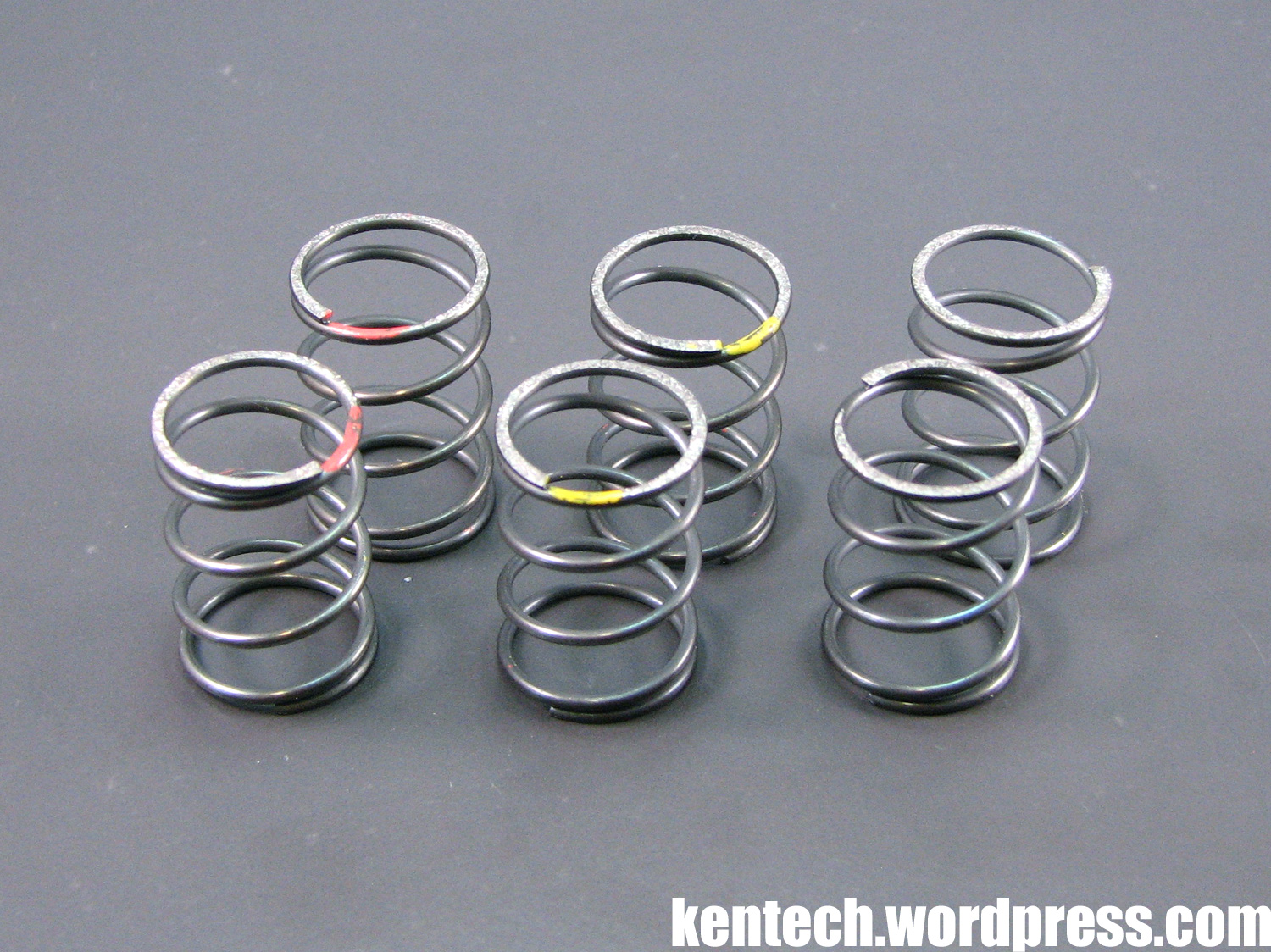
Three pairs of springs are included with the GZ1:
– Medium/Soft (Red)
– Medium (Yellow)
– Medium/Hard (no marking)
The springs are a bit different to other popular springs. While the length is the same as normal springs at 25mm, the wire which makes up the spring is thinner, while there are fewer turns of wire per spring.
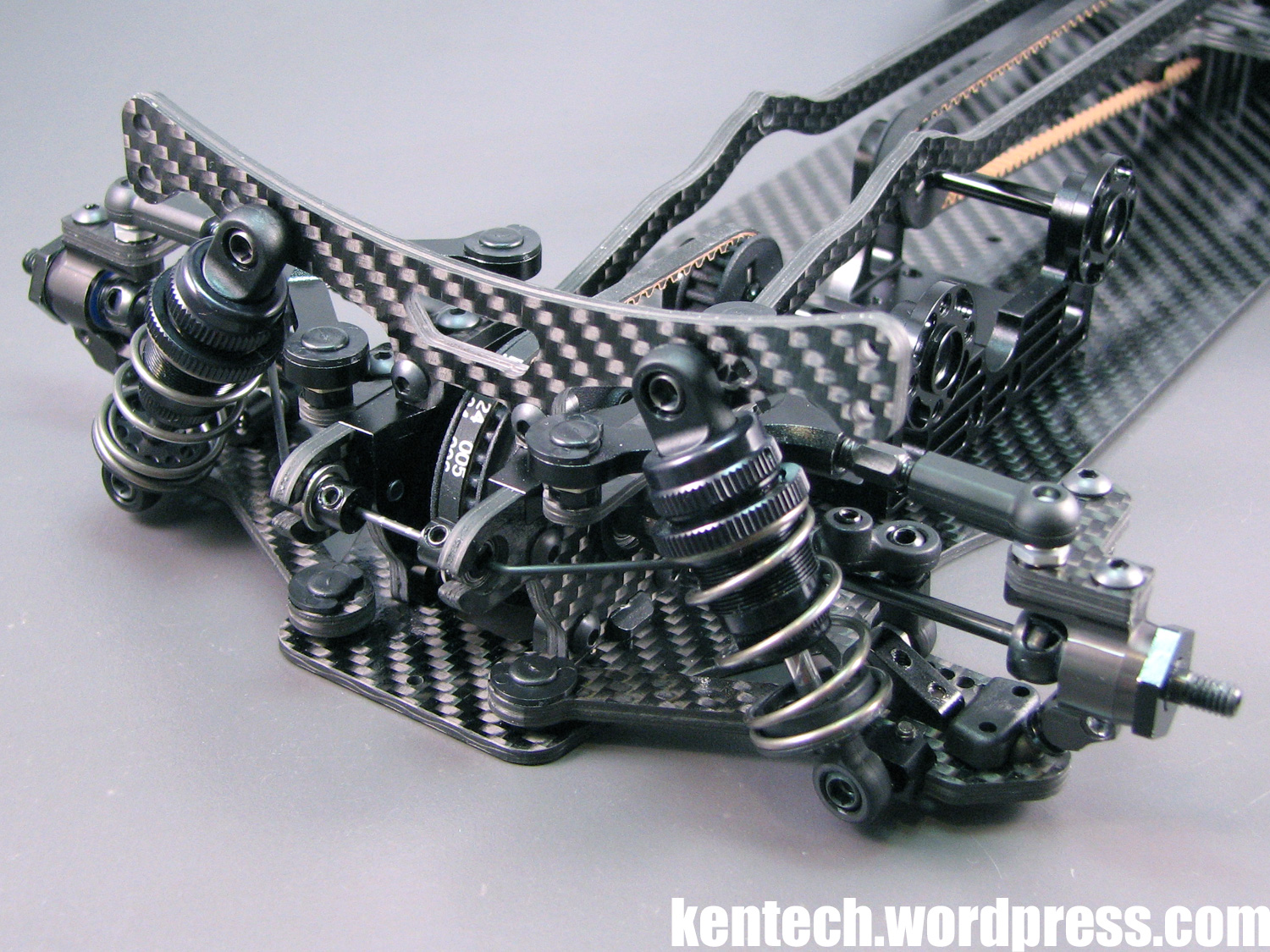
Rear dampers fitted. Xray balls for mounting the dampers, which means you need a 3mm hex wrench. The initial position on the tower is furthest in.
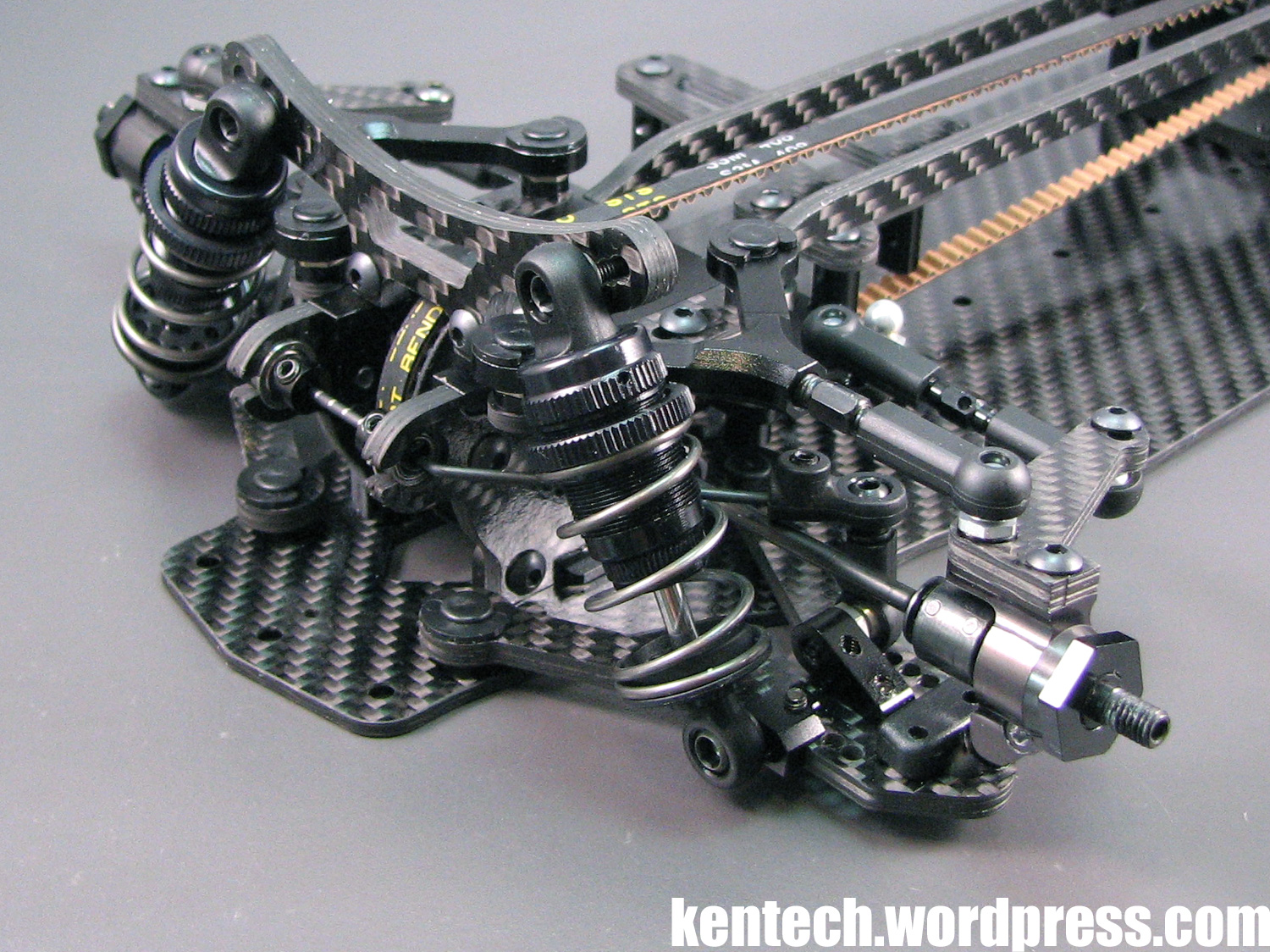
Front dampers, again using the hole furthest in on the tower for the initial setting.
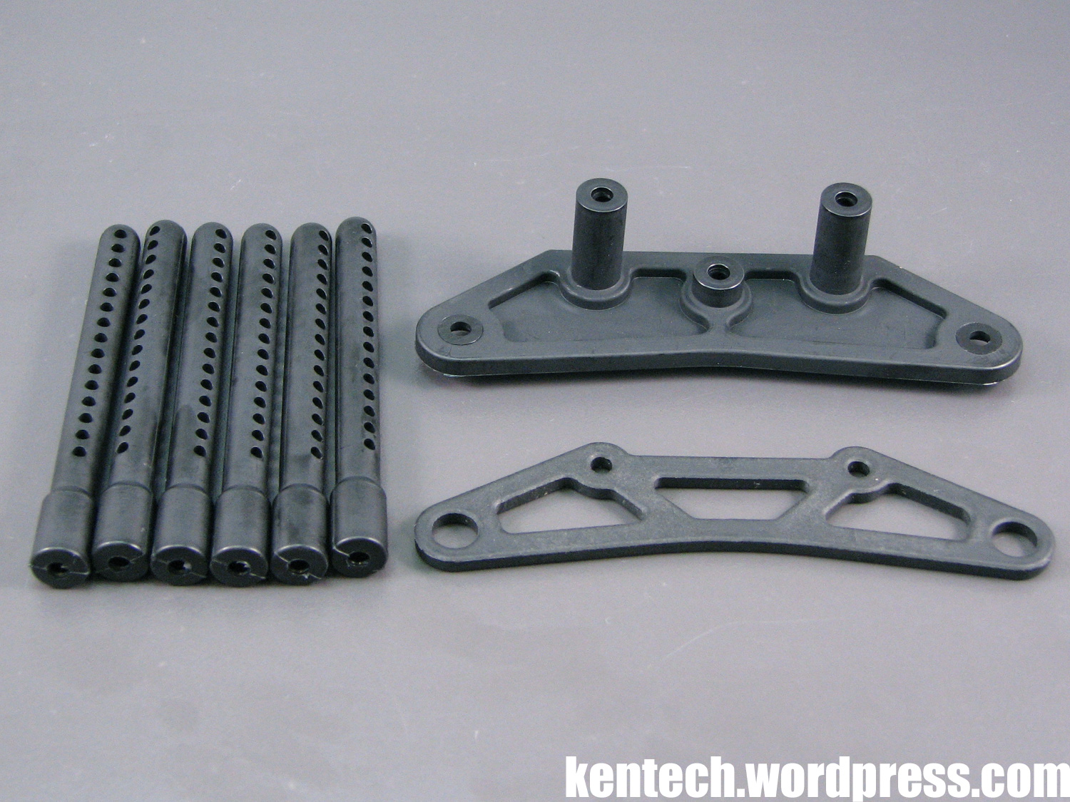
Only the final bits of the kit left to assemble now, starting with the bumper and body posts.
The front bumper is a standard design in every way. As you can see you get 6 (!) front body posts included in the kit, as well as a a plastic upper holder.
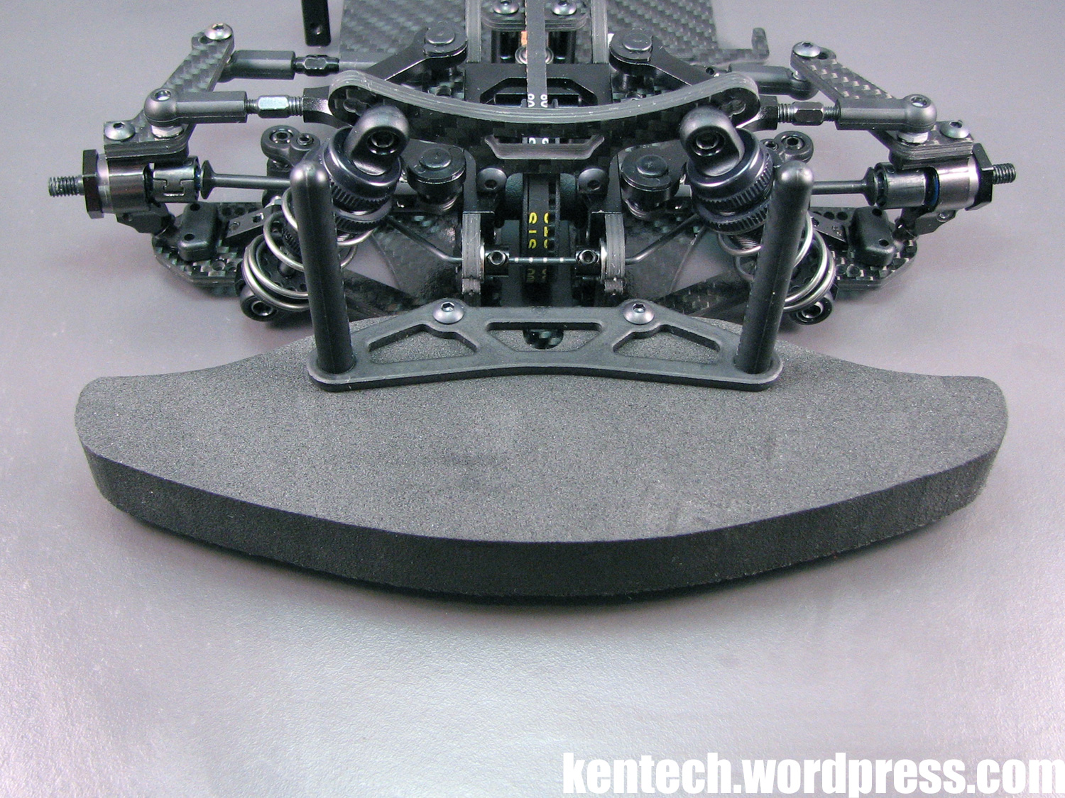
The included foam bumper is fairly hard, so it should give good support.
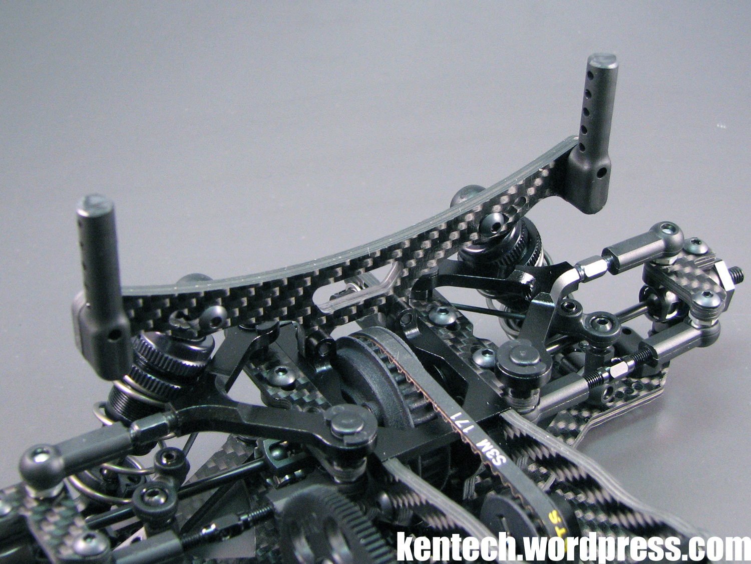
The rear body posts are again a standard design, fastened to the rear damper tower.
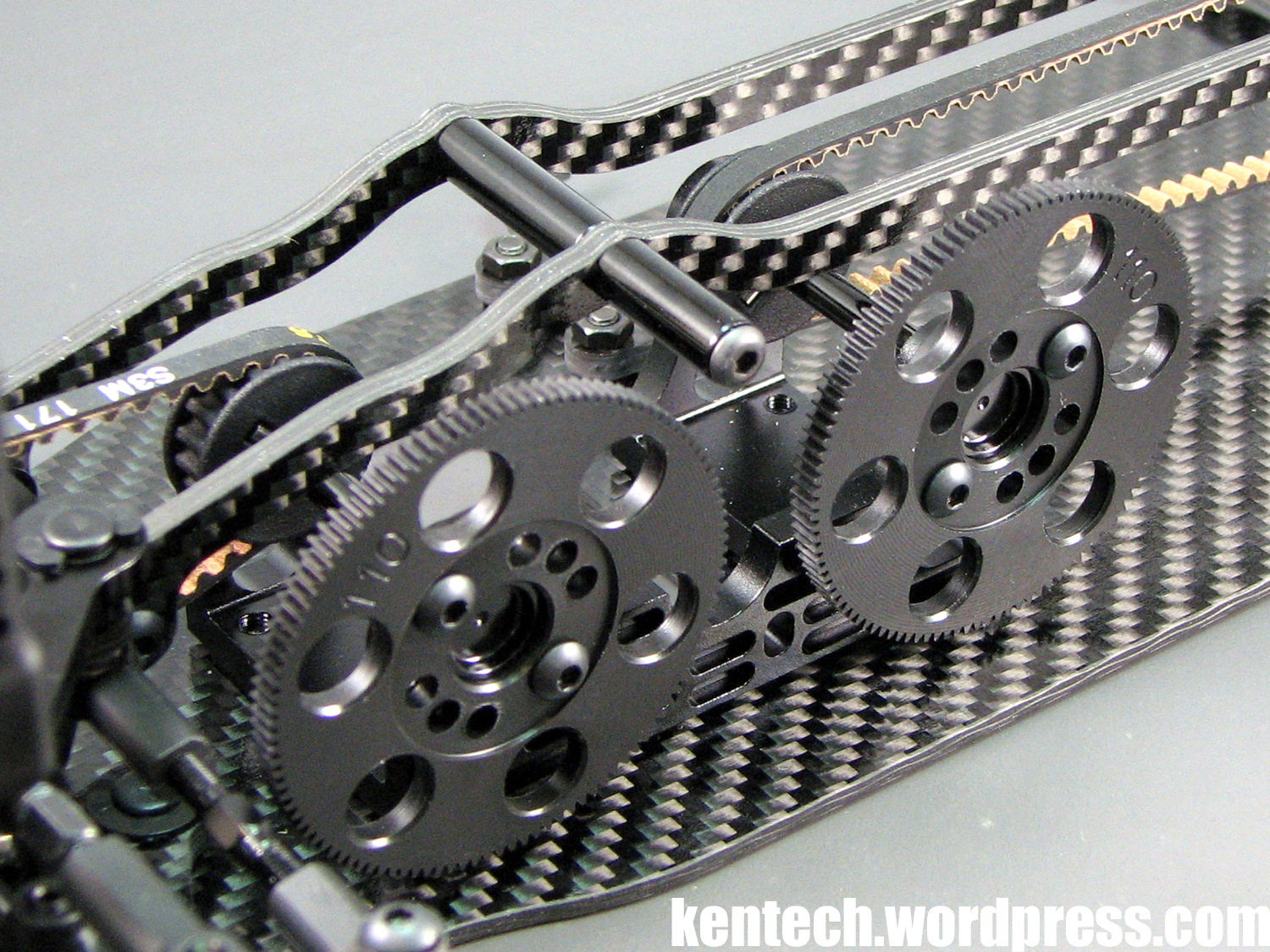
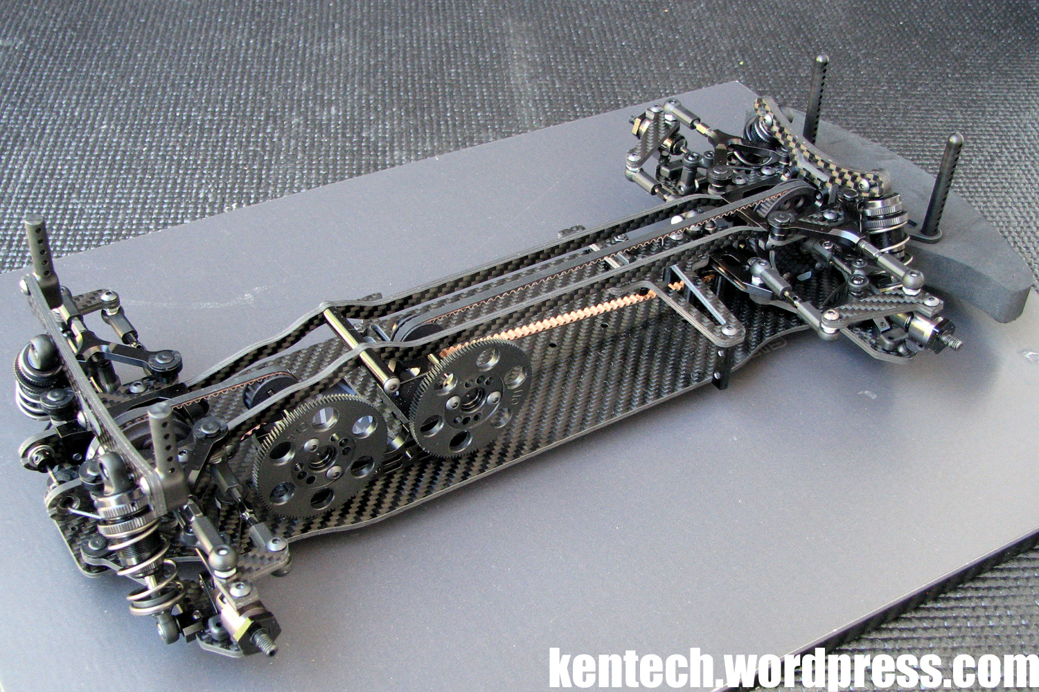
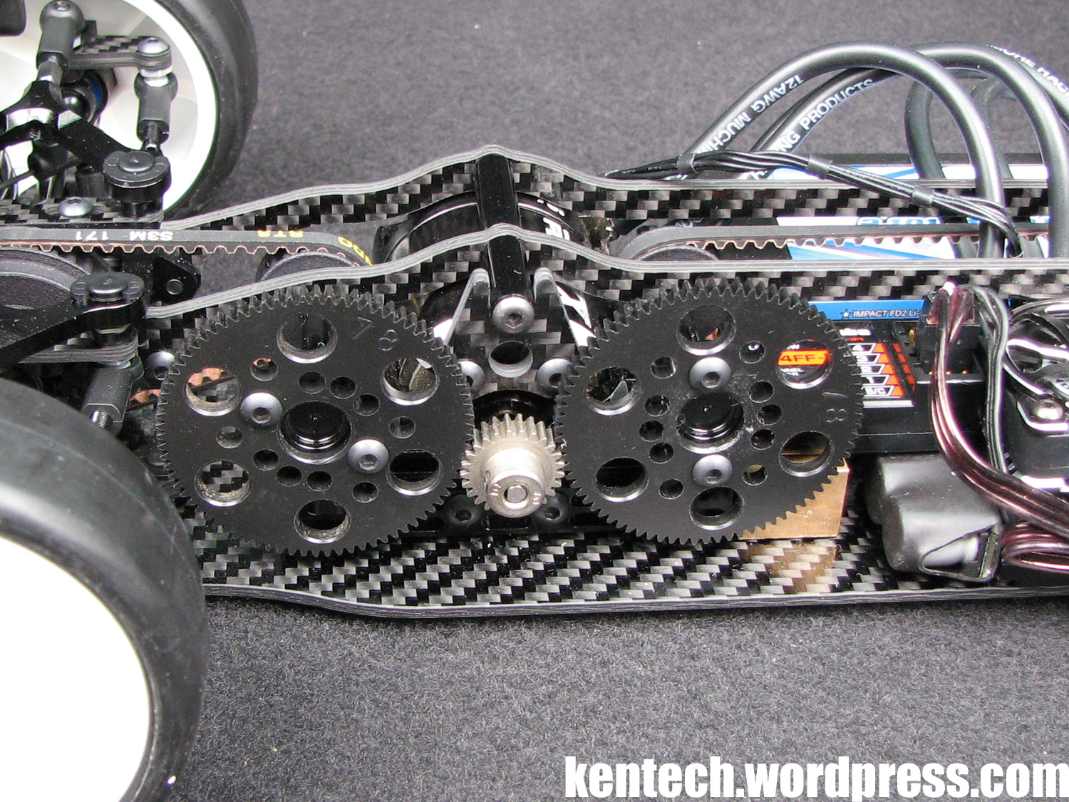
Next up the spur gears, of which there are of course two on this car. They look to be RW Racing gears, which are known for their high quality. 110T 64P spurs are included in the GZ1 kit. They are secured to the centershafts with two screws per gear.
Also fitted in the picture above is the side plate stiffener tube, which attaches the left and right side plate above the motor. There is also another tube that protrudes to the right, where it acts as a support for the carbon fibre motor bracket. This is not fitted in the picture as no motor is in the car, but I will take a picture at a later stage in another post when I fit a motor to the car.
Finally, carbon battery mounts are added to the chassis. Both are the same, and fitted with 3x10mm screws, 2mm spacers underneath, and nuts on top. They will hold the shorty battery, required for this car, in its place securely. The battery is taped in, with tape slots included in the battery mounts.
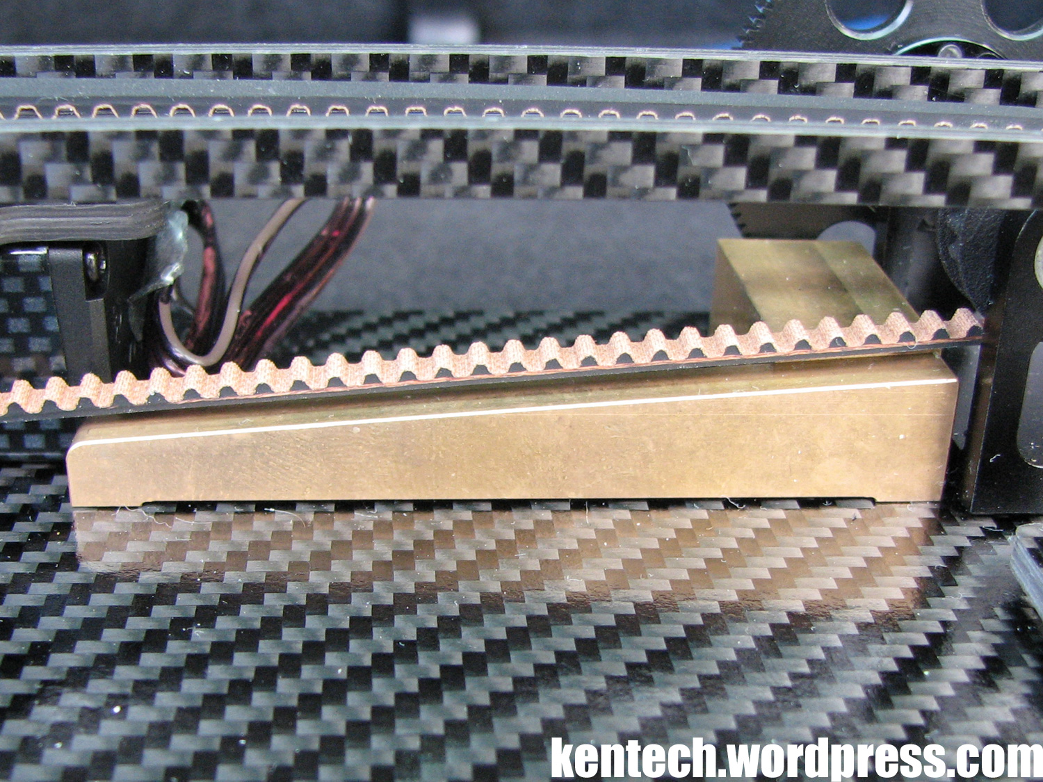
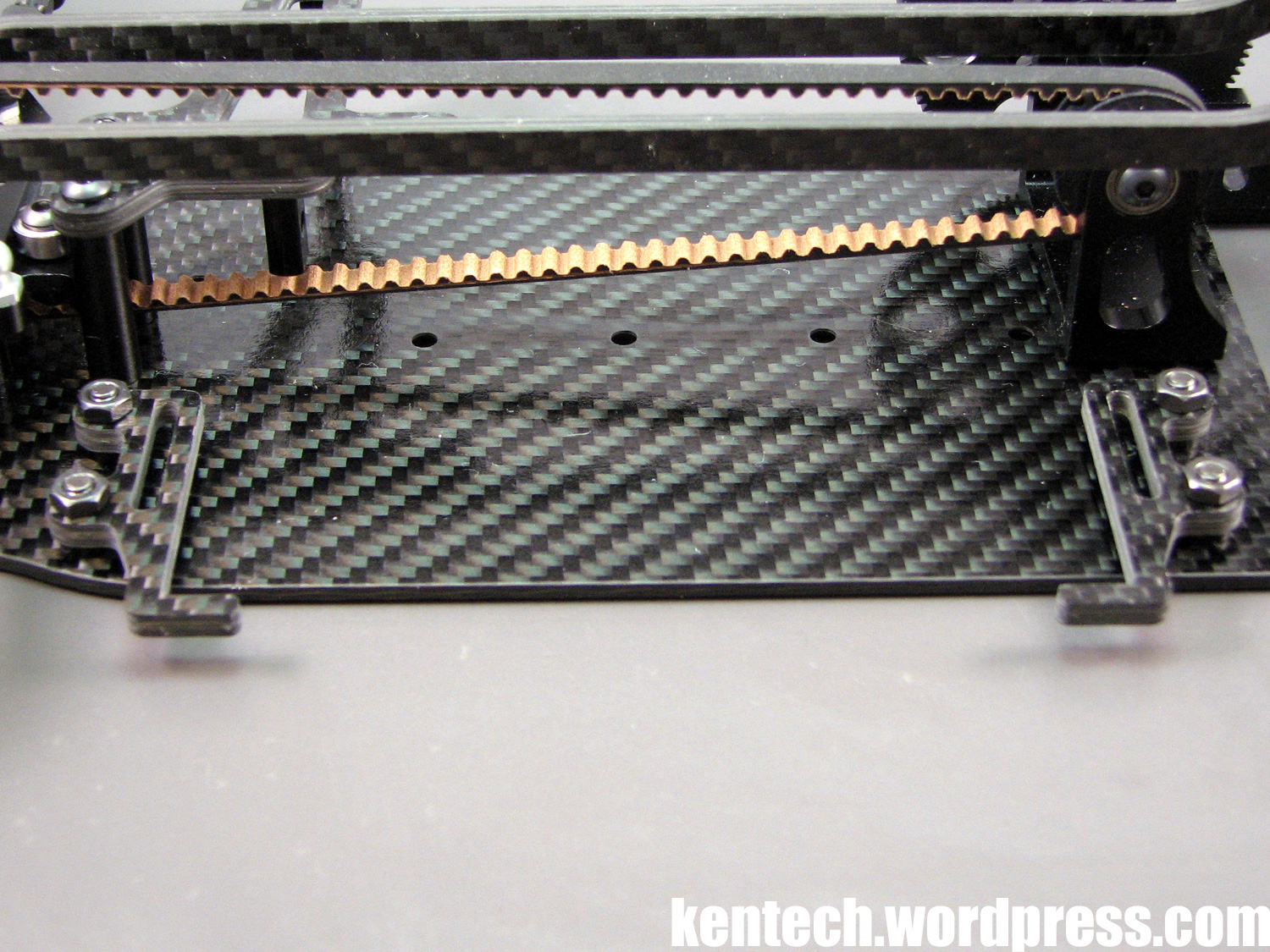
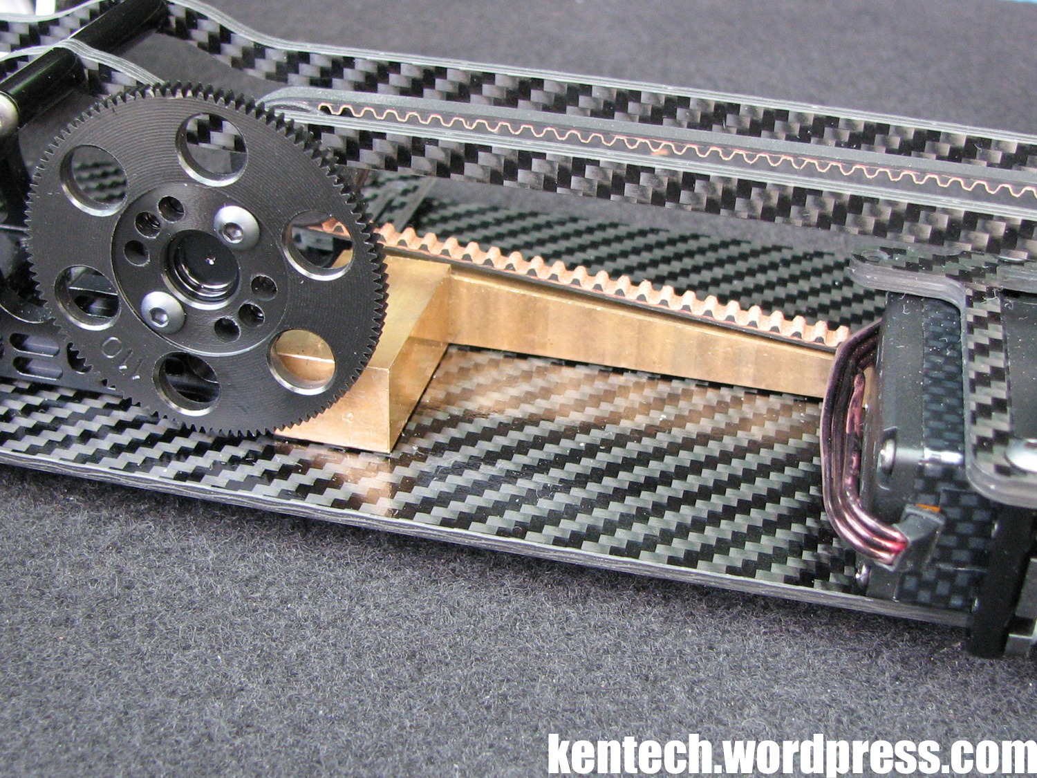
Almost forgot abou the nice brass weight that’s included with the GZ1 kit.
It’s made to fit the chassis perfectly, and helps make reaching the weight limit a bit easier, with the lightweight construction and the use of light shorty batteries making this a very light car. The weight only touch the chassis on the centerline, at the front and the rear. A normal countersunk screw is used at one end, while a grub screw is used at the other just to keep it where it’s supposed to be. Obviously you could use a normal screw at both ends, which would stiffen the chassis more.
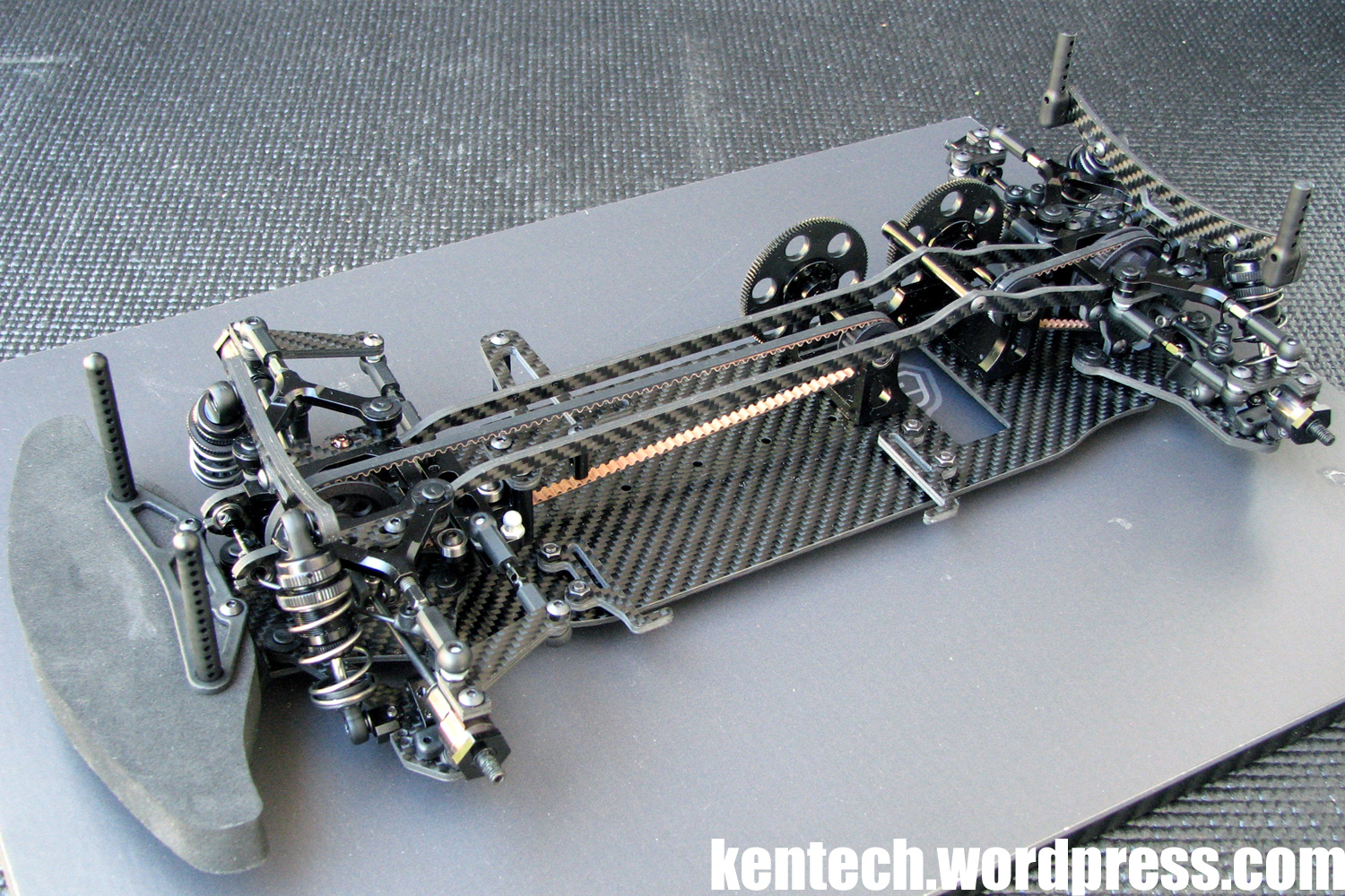
Time for a final summary then as the Gizmo GZ1 chassis is now fully assembled.
Time for a final summary then as the Gizmo GZ1 chassis is now fully assembled.
The GZ1 is clearly a pure racing car, comparable in many ways to a full-size racing car. It is not a product from a large manufacturer aimed for the masses, instead it is a high-end racing kit aimed for experienced racers. Therefore for example the manual is not as extensive as on kits from large established manufacturers, and instructions are at a minimum. All this is understandable though, and building the GZ1 is no problem as long as you have a bit of experience and take your time. Like it would be with any pure racing product.
Everythings fits together very well, and the precision throughout is impressive. The GZ1 kit is also very well equipped with lots of parts which are options on other cars included with the kit, while other features are not even available from some manufacturers. You get three pairs of different springs, double-joint front driveshafts etc.
Personally, I think the way this car has been realised and produced is super smart. Using good parts from other suppliers, and through making a fairly limited amount of own parts, Gizmo have managed to come up with a truly unique car with lots of innovations seen nowhere before.
It really is time for the major manufacturers to take notice.
Finally a couple of pictures of the Gizmo GZ1 all assembled.
Follow up posts on testing the car, and so on, will follow in the coming weeks.
Hope you have enjoyed the GZ1 build and it has given you a chance to get a better idea of this unique kit. Thanks for reading!
http://www.gizmoracing.com/
http://www.facebook.com/Gizmoracing/
First Gizmo GZ1 Test
Took the chance to already test the GZ1, pretty much straight after completing its build.
In total I spent amost a full day with the car.
Putting all the electric components in that car requires some precision, as there is no extra space in the car. It all worked out well though, and had I had a bit more time on my hand it would have looked better as well.
Seen in the picture below is the motor support I mentioned in the extensive build review of the GZ1. As you can also see in the picture, I went with 48P spurs for this test, as that’s what I had in my boxes of stuff that fit the car and the ratios I were after. I was planning to run a Tamiya 105T gear, but the front one touched the centre ballast weight, so it’s worth noting that this might be the case with thicker gears. Anway, the RW’s are excellent and fit the car perfectly. Setting the gear mesh is very easy with nothing hiding the gears, so visibility is easy.
You might notice in the next picture that I run a low Muchmore 4000 lipo. I had planned to run the Muchmore 5000 shorty, but found that the insidebattery connector hit the upper deck. I did not really want to spend time engineering a solution for this, as I was at the track and wanted to use the day for testing. I will work out a solution for a higher battery later.
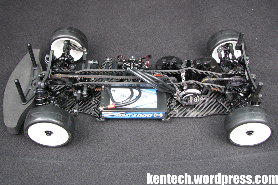
I run weights under this low battery instead, to make it equal to the 5000 weight, to easier reach the weight limit of 1350g.
Because of this super light battery, I obviously had to run lots of weights. But even with the larger and heavier 5000mah battery, and the large included brass weight in the car, I still had to add 45g to the car. That’s with a Savöx 2263 servo, Muchmore Pro ESC and motor, Schumacher Sorex 32 tyres and a custom painted LTC-R LW body.
Priority nr 1 – The car run reliably for all day without issues.
Obviously with the suspension system used, a small brush with wall or such will cause settings to be changed quite easily. This happened 2 times during the day. Obviously all cars need to be checked after such issues, but running a car with this sort of suspension will always require you to do a bit more setup checks if you happen to have some incidents.
I guess the one thing you want to know is the speed of the car. Since I had run a full day with the TRF419X the previous day on the same track in similar conditions, a comparison was possible to make. I tried to keep all factors as equal as possible, and as this was the first real test with the 419X it was also quite fair in that sense, even if I have many years of TRF experience.
I did the fastest laptime with the Gizmo, while I did the fastest 5 min run with the 419X. But the laptimes were within 1 tenth in comparable track conditions, and the 5 min result within 1 second! So that should give you a pretty decent answer to where the car was at this first run.
There are so many things to try, and I look forward to more testing. I was very happy with the GZ1 throughout the day. No bad traits, no problems, and the cars were surprisingly similar on track.
For this first test I focused a lot on dampers and springs, but maybe we’ll save details for a later date and after more running.