|
- Team Associated TC6.1 - Tony Phalen - Build -
The TC6.1 is Team Associated’s flagship onroad touring car. This car is the next generation to the A-Team’s successful TC6, adding a few refinements and additional go-fast goodies to make it a winner right out of the box. You can find the full, step-by-step build up right here on CompetitionX. Testing and my final thoughts will be posted in an upcoming review.
The following Tamiya Option Parts were included and will be used with the build:
Team Associated XP DS1015 Steering Servo,www.rc10.com
LRP SXX Stock Spec V2 Brushless Speed Control, www.rc10.com
Reedy Sonic 17.5 Brushless Motor, www.rc10.com
Solaris Pre-mounted TC Slicks, www.solarisrp.com
Airtronics M11X, www.airtronics.net
Protoform P37-R Lightweight Body, www.racepf.com
Part 1 – Shocks
We are going to start the build with the shocks. Thankfully, Team Associated has done some updates to their shocks, making them much easier to build and maintain. This might also be a good time to review any setups you want to duplicate. Changing the oil and/or pistons can pretty much suck after you’ve built them.
Build Notes:
Shock oil can be pretty messy. Have a clean work area and some paper towels or rag handy in case you spill any.
A pair of calipers is suggested to help measure the length of the shocks. While not necessary, this step will help you build a perfectly balanced Touring Car.
It is also suggested that you find some sort of shock stand to help with building your shocks. You can always build a makeshift one from a piece of scrap cardboard.

Step 1
To start off, remove all of the shocks parts from the package and group them together on your clean pit space. This will make it easy to grab the parts you need when you need them.

Step 2
The manual instructs you to insert the o-ring into the threaded collar in a later step. I did follow the manual but, after wrestling with the shock oil and oily parts, this became an almost impossible feat. Even after washing the parts it was still quite a chore. My suggestion is that you do this upfront and avoid the ‘oily-finger’ syndrome.

Step 3
Take the 4 shock bodies and slide the larger, black o-ring over the bottom part as shown in the picture.

Step 4
Insert the piston bushing into the piston, flange side down. Slide that over the smaller threaded end of the shock shaft and secure with the small 2x4mm button head screw. A SMALL dab of loctite here will help keep the screw in place. Build 4 shafts.

Step 5
Slide the shock shafts through the bodies, as shown. Apply a small drop of shock oil to the threaded part of the shock shaft and carefully slide the o-ring spacer, o-ring and hat bushing onto the shaft. Note the direction of the hat bushing. Slide all three pieces over the threades and seat into the bottom of the shock body. Slide the VCS3 shock bottom cap over the shaft and screw on to the bottom of the shock body. Be careful not to cross thread the cap. Firmly tighten into place.

Step 6
Screw on the shock shaft eyelet onto all 4 shocks.

Step 7
Using a set of calipers, measure the distance between the bottom of the shock (bottom shock cap) and the top of the eyelet as shown. It is suggested that you make all 4 the same.

Step 8
Take one of your shocks and fill it to the top with shock oil. Push the shock shaft up and down SLOWLY to allow any air under the piston to escape. Once you’ve done this a few times, refill the shock to the top. My suggestion is to fill it until it is completely level with the top of the shock body. Set this shock aside in your pro shock stand or your janky (but useful) homemade, cardboard stand. Repeat this process with the other 3 shocks. We need to let the shocks ‘rest’ for a few moments to make sure all of the air bubbles can escape.

Step 9
Ok, messy time! Take the first shock you added oil to and wrap it in a paper towel as shown. Fold the shock bladder in half and slowly place it on top of the open shock. The best procedure is to start on one side and ‘roll’ the bladder across the opening. This will force any extra oil out of the shock and onto the towel you wrapped around the it!

Step 10
Place the shock VCS3 shock cap onto the bladder and slide the aluminum cap retainer over it. Slowly tighten down the cap retainer until it is finger tight. Be careful not to cross thread it. Move the shock shaft up and down to make sure you have full throw of the shaft.

Step 11
If you added different weight oils to the front and rear shocks, it’s best to keep the separated at this point. Mixing them up would be bad.

Step 12
Finally, thread the spring collor onto the shock, slide the spring in place and insert the lower spring retainer. Wah-lah…4 happy little shocks. Remember to keep them separated if you build a specific front and rear set.
Part 2 – Differentials
Next on the TC6.1 build is the differentials. The TC6.1 comes with a front spool (very little build time) and a rear gear differential. The rear gear diff is quite unusual for a touring car but is starting to become more and more popular because of it’s extreme durability and requires very little maintenance. It is a pain, however, to adjust as it requires you to remove it completely from the car, dump all the old fluid and pour in new fluid.
Build Notes:
As with the shocks, you’ll be dealing with some diff fluids that can be messy. Gather up some freshy rags to help keep that mess to a minimum.
You’ll also be required to glue the spool gear together using CA. Be careful and try and keep it only on the side of the gear teeth, not on the face. Some CompetitionX Gloo Toobs will definitely help out in this area of the build!

Step 13
Start by laying out the parts for the front spool.

Step 14
You’ll need to glue the flat gear ring onto the spool gear. EASY glue application is required here so you don’t drip the glue onto the face of the gears. I recommend using some of my CompetitionX Gloo Toobs. They make life a WHOLE lot easier. NOTE: You’ll notice the flat gear ring will have a completely flat side and a slightly curved side. The completely flat side will face AWAY from the gear. Set it aside for about 10 minutes to make sure it glues completely before moving to the next step.

Step 15
Take your freshly glued gear and slide it over the spool. The long side of the spool should feed through the opening in the gear. Attach the 4 2x4mm screws into place. A dab of loctite here is recommended.

Step 16
Time to piece together the 4 bearing cams. The best advice is to just take your time and follow the manual instructions. You’ll want to build two front and two rear and keep the separated from each other.

Step 17
Slide the bearing shim onto the spool. Take your bearing, press it into the bearing cam and slide that onto the spool. Make sure you slide it on bearing-first. Take your plastic spool outdrive and key it into the end of the spool. Follow that up with the 2.5x10mm screw. A little dab of loctite here is recommended. Repeat for the other side.

Step 18
Now for the fun part…the rear diff. Actually, it’s not quite as bad as a ball diff. Just build it and forget it! Start by getting all of the rear diff parts together. You’ll also want the black grease and diff fluid handy.

Step 19
Take your outdrive and set it on it’s end. Slide the shim onto the outdrive (make sure you use the correct shim – it’s the larger of the two shims) followed by the larger o-ring. Once the o-ring is in place, liberally squirt some black grease on top of the o-ring. More is fine in this instance.

Step 20
Now take the smaller o-ring and slide it over the outdrive shaft and seat it into the small recess on the shaft. You can coat this o-ring with black grease too.

Step 21
Slide the outdrive into the larger diff half. Take the smaller shim and drop it into place over the shaft. Carefully slide the retaining pin into place. Coat the pin with a bit of black grease to help keep it centered.

Step 22
Drop the sun gear into place. If you coated the pin with black grease as stated in the last step, the sun gear should stay in place also.

Step 23
Build a pair of satellite gear sets. The shims go on after the gears are in place. Again, a little black grease will keep things in place.

Step 24
Take one of the satellite assemblies and lower it into the diff half, aligning the pins with the slots. Make sure the first assembly has the ‘slot’ pointing up as shown.

Step 25
Now lower the second satellite assembly into place, but this time make sure the ‘slot’ is facing downwards. Done correctly, the ‘slots’ from the satellite assemblies should align and fit together. Set this assembly aside.

Step 26
Take your second outdrive and slide it up into the flat gear half. Slide the shim and pin into place like you did with the other half. Again, black grease will hold things in place.

Step 27
Drop the sun gear into place.

Step 28
Take the larger diff half and fill it up with diff fluid until it’s about 80% full. SLOWLY rotate the outdrive to help distribute the fluid into all the nooks and crannies. Refill it up to about 90%. You don’t want it too full or it’ll be a mess in the next step.

Step 29
Take the thin rubber gasket and feed it into the slot on the larger diff half. It is extremely important that the gasket be seated completely before moving on! Align the holes in the flat diff half with the holes in the other diff half and lower into place. Use the 2.5x6mm screws to secure the halves together.

Step 30
Press the bearing into the bearing cam. Slide a bearing shim into place followed by the bearing cam. Make sure you install the bearing cam bearing side first. Boom! Done!
Part 3 – Drive Axles and Turnbuckles
The drive axles and turnbuckles are the final ‘prep-steps’ before getting into the meat of our build. These are simple steps and shouldn’t take you long to complete.
Build Notes:
Get your black grease and paper towels ready for the drive axles. A liberal amount will help keep the parts nice and lubed.
Pay attention to the length of the turnbuckles. There are three different lengths and you don’t want to mix them up during the build.

Step 31
Take your drive bone and apply some black grease to the ball end. Slide the CVA coupler into the ball and position the cross pin hole so that it is perpendicular with the actual bone.

Step 32
Apply some more black grease to the outside of the drive bone ball and insert it into the CVA axle. Align the cross pin hole in the axle with the cross pin hole in the CVA coupler and slide the cross pin into place.

Step 33
Slide your retaining clip on the CVA axle (from the thread side) and push it up and into the groove in the axle. When doing this, make sure that the ‘break’ in the retaining clip does NOT align with the cross pin. You don’t want this pin falling out while driving!

Step 34
For added security, you’ll want to screw the setscrew into the CVA coupler to lock the pin into place. A small dab of loctite will help keep the setscrew locked in.

Step 35
The final step with the drive axles is to install the CVA blade. This can be a bit tricky at first. The hot ticket is to start from one side and push the blade so that it engages the pin in one hole. Now take the blade and force it over the ball and onto the other pin. The picture shows the ‘starting point’. Once you do one, you’ll blow through the other three. Oh, if you haven’t already built the other 3 drive axles, do so now using the steps we just went over.

Step 36
AE has supplied the TC6.1 with 3 different sizes of blue-anodized turnbuckles. The shortest is the drag link from the servo to the bellcrank, the 4 mid-sized ones are the camber links and the long ones are the steering links. Don’t mix them up!

Step 37
Build the turnbuckles per the instructions. The only real tip I have to offer is to have a gloves or a paper towel or something to help turn the plastic eyelets. When the assemblies get shorter, the eyelets become harder to screw on. You’ll lose a little finger skin with this step. Welcome to turnbuckles.
Part 4 – Front Suspension
The front suspension is pretty straightforward; suspension arms and bulkheads. AE has cleaned up the arm mounts and made them much stronger than the TC6.
Build Notes:
Suspension arm shock inserts have been added to the TC6.1. Make sure you get insert them equally in both arms.
The same can be said for the arm mounts. Pay close attention that you build both the left and right sides the same.

Step 38
Let’s start with the pair of front suspension arms. Take you inserts and install them as the instructions show. The might take a bit of pressure to insert. Make sure you build a left and a right.

Step 39
Next, insert the droop screws. We’ll set these later.

Step 40
Screw in the ball lower shock mounting ballstuds into the arms. These should feed through the plastic pieces you inserted a few steps ago. Once those are tight, slide the long hinge pins into place.

Step 41
The arm mounts on the TC6.1 are now one piece and of different thicknesses (before there were various, thin inserts to control the width). Much better design now…thank you AE. Choose the widths you want and insert the blue aluminum inserts as shown. I would suggest starting with the kit arm mounts (0 offset).

Step 42
Take your arm mounts and, as shown, slide them on the hinge pins. Don’t forget the wheelbase shims. A 1mm shims should go towards the front of the arms (the shock mount ball end side) and a 2mm shim should go on the rear of the arms. If you are having trouble keeping the assembly together, put a dab of black grease on the end of the hinge pin. That will help keep the arm mounts in place. Also, note the direction of the arm mounts (VERY IMPORTANT).

Step 43
Using the 3x12mm screws (with a dab of loctite), mount the suspension arms to the bulkheads using the upper attachment hole (note the direction of the bulkheads). Team Associated has made all 4 of the aluminum bulkheads the same so there is no worries about mixing them up. Again, note the direction of the arm mounts and arm mount inserts. You’ll want these to be like the picture.

Step 44
Once attached, pick up each assembly and make sure the arms move without ANY friction. If they don’t try loosening the 3x12mm screws and re-aligning the arm mounts.

Step 45
Attach the pair of bulkheads to the chassis with the 3x5mm screws. A dab of loctite on these screws will ensure they don’t come loose while you’re on the track. Note the direction of the arms.
Part 5 – Rear Suspension
The rear suspension is an almost exact duplicate build as the front suspension. If you’re doing this build in order (which I hope you are), this step should be quick and easy.
Build Notes:
As with the front suspension, arm shock inserts have been added to the TC6.1. Make sure you get insert them equally in both arms.
Again, make sure you pay close attention to the direction of the arm mounts.

Step 46
As you did with the front suspension arms, press the arm inserts into the arm as the directions show. You’ll want to be using the middle hole (I am following a different setup so the picture shows the outside hole).

Step 47
Screw the droop screws into the arms. Again, we’ll adjust these at a later time.

Step 48
Screw in the shock mount ball studs and slide the inner hinge pins into place.

Step 49
Assemble the arm mounts. We are using the 0 dot (or 0 degree) mounts. Pay close attention to the assembly to make sure you have a left and right set.

Step 50
Take your arm mounts and, as shown, slide them on the hinge pins. Don’t forget the wheelbase shims. A 1mm shims should go towards the rear of the arms (the shock mount ball end side) and a 2mm shim should go on the front of the arms. If you are having trouble keeping the assembly together, put a dab of black grease on the end of the hinge pin. That will help keep the arm mounts in place. Also, note the direction of the arm mounts (VERY IMPORTANT).

Step 51
Using the 3x12mm screws (with a dab of loctite), mount the suspension arms to the bulkheads using the upper attachment hole (note the direction of the bulkheads). Again, note the direction of the arm mounts and arm mount inserts. You’ll want these to be like the picture.

Step 52
Once attached, you’ll want to do the swing test like you did for the front arms. Remember, we want zero friction when swinging the suspension arms.

Step 53
Attach the pair of bulkheads to the chassis with the 3x5mm screws. A dab of loctite on these screws will ensure they don’t come loose while you’re on the track. Note the direction of the arms.
Part 6 – Motor Mount
The motor mount on the TC6.1 is a simple 3-step process. Get ready for easy.
Build Notes:
The motor mount on the TC6.1 is all aluminum. This means you’ll want plenty of loctite on the screws to help keep them in place.

Step 54
Start off by attaching the left and right spur-gear bulkheads. These two aluminum pieces are exactly the same so there is no worry of mixing them up.

Step 55
Next, attach the actual motor mount. Don’t forget the loctite.

Step 56
Finally, attach the motor mount brace. Don’t forget the loctite here, either.
Part 7 – Shock Towers
Other than the shape of the shock towers and the positioning of the shock mount and camber links, the front and rear towers go together exactly the same way. Team Associated has done away with the directional bearing caps and made all four of them the same, removing any chance of assembling something the wrong way.
Build Notes:
While the bearing caps mount the same front and rear, the direction of the shock towers is crucial. One side is flat while the other has recesses for the screws. Make sure you note this direction.

Step 57
Take the front shock tower (the smaller of the two towers) and insert the camber link ball end into the #3 hole (see diagram in the manual). Capture it with a blue locknut. Note the direction of the tower!!!!! The side with the recessed screw holes should be on the same side as the ball end.

Step 58
Next, install the upper shock bushing into the #3 hole (see diagram in the manual). A dab of loctite here will help keep the screw in place.

Step 59
Take any 2 of the 4 bearing caps and, using a pair of 3x6mm screws, attach them to the shock tower. DO NOT TIGHTEN COMPLETELY (we will do this in a later step)! You can, however, add a dab of loctite here to help keep the screws in place. Also note the direction of the tower in relation to the bearing caps.

Step 60
Now follow the same procedure on the rear shock tower. Camber ballstuds in hole #3 and attaching on the same side as the recessed screw holes.

Step 61
Attach the body mounts to the rear tower using the 3x6mm screws. Note the side of the tower the actual plastic mount is mounting to.

Step 62
Attach the shock bushing into hole #3 like you did with the front tower. Don’t forget the dab of loctite.

Step 63
Finally, attach the bearing caps but do not tighten completely. We will do this in a later step. Again, loctite and note the direction of the caps in relation to the recessed holes in the tower.
Part 8 – Steering
While the steering setup on the TC6.1 is similar to other cars, the way the Ackermann is adjusted is all new. It’s very easy to adjust and doesn’t require you to disassemble anything. Oh, and it goes together quite easily.
Build Notes:
Be very careful when installing the C-clip on the bottom of the servo saver assembly. It’s small and will *boing* a long way if you don’t take care. Oh, and you’ll probably never find it again.

Step 64
Take the 7mm bellcrank arm and install the two short ballstuds into it. The serrated side of the arm should face up.

Step 65
Take the upper bellcrank, align the serrated side with the serrated side of the lower bellcrank and secure with the 3x8mm screw. Align the notches on the side so that you will be using the ‘B’ setting. Yes, I know my picture shows the ‘C’ setting. I’m actually trying a different setup to start with.

Step 66
Insert a short ballstud into the servo saver arm as shown.

Step 67
Pre-compress the servo saver spring using a pair of pliers (or your fingers if you’re a real man!). Slide the bellcrank tube down through the servo saver arm and then through the bellcrank assembly. Align the notches in those two pieces so they sit as shown in the manual. Slide the spring over the bellcrank tube followed by the servo saver nut. Screw the nut down. We’ll adjust it in a second.

Step 68
Press a bearing into each end of the bellcrank tube…

Step 69
…and then insert the steering post. Clip the C-clip into the notch on the steering post. Again, be careful not to ‘fling’ the C-clip across the room!

Step 70
Adjust the servo saver nut until there is a .5mm gap as shown in the instruction manual. Get as close as possible if you don’t have a way to measure it. Now press the steering post into the post insert. Either hole will be fine as this point.

Step 71
Rotate the steering bellcrank post insert so that the ‘open’ hole is towards the front of the chassis. Press the insert into the cavity as shown. Your assembly might not stay in place if you move the car around so, if you choose to remove the steering assembly (or it falls out), just remember that the ‘open’ hole is towards the front.
Part 9 – Spur Gear & Belts
In this step we’ll assemble the spur gear to the center hub as well as attach the front and rear belts. We will also be installing the front spool and rear diff.
Build Notes:
Not to much to say with this step other than to have a little loctite handy for a few of the steps.

Step 72
Start by sandwiching the 87T spur gear inbetween the spur gear hub and clamping ring. Only 3 3x5mm screws are required and will need a dab of loctite.

Step 73
Next, press the 20T pullies onto the flanges on the spur gear hub. They should ‘snap’ into place.

Step 74
We are now going to assemble the spur gear shaft. Start pressing a bearing into each side of the spur gear assembly. The flange of the bearing should be on the outside. Take the spur gear shaft and snap an E-clip in the groove at one end of it. Slide a shim into place and then slide the gear shaft through the bearings on the spur gear assembly. Slide the second shim into place and snap the final E-clip into the groove.

Step 75
Untwirl both belts (I think untwirl is a word)…

Step 76
…and wrap them around the spur gear assembly. Drop the spur gear assembly inbetween the bulkheads on the chassis and install the 2.5x8mm screws to secure it in place. Don’t forget a dab of loctite. Also note the belts in the picture; verify they are on the correct side of the spur gear assembly. Take the rear diff and, after wrapping the short belt around it, slide it into place within the rear bulkhead halves.

Step 77
Take the front belt and wrap it around the spool. Drop the spool into place between the front bulkheads. Pay attention to which side of the belt the steering assembly goes on.
Part 10 – Top Deck
We have split the top deck up into its own step simply because it is a pretty crucial step. We want to keep the chassis as flat as possible during this part of the build.
Build Notes:
Most of the screws in this step tap into aluminum parts. Make sure you apply loctite to all those screws prior to tightening them down.
Because it is very important that the chassis be flat during this part of the build, a clean, flat surface is required.
You’ll also want to make sure you don’t tighten down the screws as you install them. Wait until you’ve installed ALL of the screws into the top deck before tightening, and tighten them down in a crossing pattern; one from one side, cross over and tighten one from the other side. This will ensure that you don’t tweak the chassis at all.

Step 78
The first step is to make sure you are on a clean, flat, solid surface; no pit towels or rippled plastic boards. We need a super-flat surface. Next,feed the chassis through the front belt and lay it down on the bulkheads. Make sure the beveled screw hole is facing up. Now thread in the 4 3x5mm flat head screws into the front 4 holes, then insert the 3x5mm button head into the top of the steering. Do not overtighten…just put them in far enough to hold the top deck in place.

Step 79
Next, insert the 4 3x5mm flat head and 2 3x5mm button head screws into the rear holes in the top deck. Press down firmly on the top deck (near the rear bulkhead) and tighten down the 6 screws in a crossing pattern. The idea by pressing down on the top deck is to make sure the chassis is perfectly flat when we tighten down the screws. Now follow the same procedure for the front end.

Step 80
Drop the front shock tower assembly on to the front bulkheads. Lightly tighten the screws down, making sure the tower mounts are ‘square’ with the bulkheads. Now tighten them down. Don’t forget the loctite.

Step 81
If you remember we didn’t tighten down the screws on the shock towers (if you did, loosen them up and go back to the step above). Now is the time to tighten them down. Do so in a crossing pattern to ensure the tower stays squared up to the tower mounts.

Step 82
Drop the rear tower assembly into place and tighten the screws. Make sure they tower mounts are square to the bulkheads and tighten in a crossing pattern.

Step 83
Complete this step by tightening down the shock tower screws.
Part 11 – Steering Knuckles
Up next is the front steering knuckles. AE has updated their caster blocks with adjustment inserts. These inserts can be changed to allow different degrees of caster. The rest of this step should be pretty simple, especially since we already built the CVA’s.
Build Notes:
The front caster block inserts are a press-fit. Just in case, I would suggest applying a VERY small dab of CA glue to keep them in place. Use as little glue as possible so you can still take them apart for tuning purposes.

Step 84
Start this step by inserting the 5mm ballstud into the holes as shown. Do not overtighten. Next, press the bearings into the steering blocks. Don’t forget to install the crush tube inbetween the bearings.

Step 85
You’ll need to decide at this point how much caster you’d like to run. We’ll assume you’re going to fly with the 4 deg insert to start. Press the 4 deg inserts into the caster blocks, ensuring that the molded number is at the top of the insert (see manual).

Step 86
Take your already-assembled CVA’s and insert them into the assembled steering blocks.

Step 87
Drop the caster block bushings into the caster blocks as shown. If you’re a pro-builder, you should be able to this and the next step without any aids. If not, add a dab of black grease to help keep the bushings in place.

Step 88
Take the CVA and feed it through the caster block. Slide the steering block into place and secure with the 8mm ballstud (on top) and 3x8mm button head (on the bottom). Snug them down; do NOT over tighten. Rotate the steering block to make sure there is not binding. If there is, loosen both screws 1/16th and try again. Once the steering block moves freely, you’re good to go.

Step 89
Slide one axle shim into place followed by the axle pin.

Step 90
Insert the 2x5mm screw into the clamping wheel hex. Slide the hex onto the axle and over the axle pin. Tighten down the 2x5mm screw. Do not overtighten!

Step 91
Take your assembled caster/steering block and slide it into the front arms as shown. Press the outer hinge pin into place through the arm and caster/steering block assembly.

Step 92
Capture the hinge pin with the 2x4mm button head. Line up the CVA blade with the front diff outdrive and slide into place.

Step 93
Grab your assembled steering links and snap them into place. Make sure the notch on the turnbuckle is closest to the outside of the car.

Step 94
Double check that your CVA blade is inserted into the diff outdrive. Grab your assembled camber links and snap them into place. Make sure the notch on the turnbuckles is closest to the outside of the car.

Step 95
Move the suspension arm up and down. It should move up freely and drop EASILY under its own weight. If it doesn’t, take a small pair of needlenose pliers and ‘pinch’ the camber link ball cups. This should elongate the cups slightly to allow the suspension to move easily.
Part 12 – Rear Hubs
In this step we will be building the rear hubs. AE has incorporated the same insert-style for rear toe as the did for the front steering knuckles.
Build Notes:
The rear hub inserts are a press-fit. Just in case, I would suggest applying a VERY small dab of CA glue to keep them in place. Use as little glue as possible so you can still take them apart for tuning purposes.

Step 96
Decide what rear toe you want to run and clip those inserts off the parts tree. Press-fit the inserts into the rear hubs, making sure the number is to the outside of the hub. We will be using the 0 deg hub. If you are building with a different deg hub, make sure you keep the left and right separated.

Step 97
Screw the 8mm ballstud into the inner hole on the top of the hub. Don’t forget to include the 2mm spacer. Do not overtighten

Step 98
Press 2 bearings into the rear hub. The silver crush tube should go between them. Now take the remaining 2 CVA’s and slide them into place as shown.

Step 99
Slide the axle shim in place and insert the axle pin through the hole in the axle.

Step 100
Thread the 2x5mm screw into the wheel hex but do not tighten down. Slide the wheel hex onto the axle and over the axle pin. Tighten down the 2x5mm screw.

Step 101
Take one of your hub assemblies and place it as shown, feeding the outer hinge pin in place to secure. Since we used 0 deg hubs, both the left and right hub assemblies are virtually the same. If you used a different degree, make sure you assemble the right hub to the right side of the car and the left to the left.

Step 102
Capture the hinge pin with the 2x4mm screw. Do not overtighten.

Step 103
Rotate your hub assembly up and down to make sure the movement is free. If not, you might have to re-check your hub inserts to make sure they have been pushed in all the way. Now rotate the hub up and insert the CVA blade into the outdrive.

Step 104
Snap the rear camber turnbuckle into place. Make sure the turnbuckle notches are matched up to the front camber notches. Move the suspension up and down again. It should move freely and drop easily under its own weight. If not, gently pinch the turnbuckles eyelets and try again.
Part 13 – Shocks, Front Bumper & Body Mounts
In this step we will attach the shocks, front bumper and body mounts to the TC6.1.
Build Notes:
Depending on the body you run, you might need to trim your front foam bumper. You can either do so with a dremel (pretty) or scissors/hobby knife (not so pretty). Either way, only take a little off at a time and test fit it.
Depending on the body you run, the body pivot mounts will mount in different holes. It is suggested that you pre-mark the holes prior to painting the body. You can also completely mount the body while it’s clear (except for tire cutouts).

Step 105
Let’s start by grabbing your front shocks and mounting them as shown (if you built the front and rears different you did keep the them separate, right?) A dab of loctite on the upper mount will help keep those screws in place.

Step 106
Complete the same step for the rear. Remember that dab of loctite.

Step 107
If you run a transponder with mounting tabs, AE has given you the perfect spot for it. If not, I would suggest putting the screws in anyway to keep track of them (in case you decide to move your transponder up here in the future).

Step 108
Assemble the front body mount posts to the upper bumper brace. I push a body clip through the body post hole to help hold on to it. Try it.

Step 109
Slide the foam bumper onto the upper bumper brace posts and attach this assembly to the lower bumper. 3 screws is all it takes.

Step 110
Now take that assembly and slide it onto the front of the TC6.1. Secure with the two screws on top…

Step 111
…and the two screws on the bottom.

Step 112
This next step isn’t necessary, but I did it because there was interference between the clips and the Mazdaspeed6 body I was running. I took a pair of the body clips and slightly bent them as shown. Now they feed into the body mount posts and don’t touch the body.

Step 113
Insert the bent body clip though the pivoting body mount and post. If you pre-mounted your clear body, these should be set. If not, you’ll most likely need to adjust them when you mount your painted body. Make sure both sides are in the same mounting hole.

Step 114
Complete the above step for the rear. Bent body clips aren’t necessary here, however I do it just in case.
Part 14 – Battery Tray
eam Associated has done away with the standard post-and-battery strap plan. Instead, they have crafted a pair of nifty braces that allow you to use battery tape. While this does mean an additional expense for you (anywhere from $12 to $24 for the good stuff), the result is a clean, functional setup that saves alot of weight on this side of the car.
Build Notes:
Team Associated has designed the TC6.1 to be a LiPo-ready TC. Because of that, the chassis does not have cutouts for the battery to sit in and will require you to have some battery tape to keep it in place.

Step 115
Start this step off by mounting the inner lipo brace. There are 3 different mounting locations to choose from; mount it in the center location.

Step 116
Take your two carbon fiber battery tape tabs and lightly grind away the ‘recessed’ edges between the two mounting holes. This is where the tape will come in contact with it. Doing so will help eliminate the chance of the carbon fiber part cutting through the tape and ejecting your battery in a hard crash.

Step 117
Now assemble both LiPo battery braces.

Step 118
The TC6.1 allows you to mount the battery in either a forward or back configuration. This mounting setup helps tune the TC6.1 to certain track conditions. Per the instructions, start by mounting the battery in the forward position.

Step 119
The last step is to attach the antenna mount to the chassis. Pretty simple step.
Part 15 – Anti-Roll Bars
The anti-roll bars are a major tuning option for the TC6.1 (for all on-road cars, actually). Care must be taken to make sure that these bars are completely straight and are built exactly the same on the left and right sides.
Build Notes:
The TC6.1 comes with AE’s new H.D.R.C. (High Definition Roll Control) anti-roll bar system. Since the ‘bars’ are all the same length and color (only the thickness designates them now), AE has included some shrink tubing to help tell them apart. Shrink this heat tubing onto the bars before proceeding any further.

Step 120
To start off this step, we will be building 4 anti-roll bar ballstuds and pivot mounts. It is extremely important that the distance between the base of the ball and the base of the ball cup are the EXACT same. Having these distances different can drastically change the way the anti-roll bar works.

Step 121
Attach the assembled anti-roll bar ballstud/pivot mounts to the suspension arms as shown. Tighten the screws down, but make sure the pivot ball can swivel freely.

Step 122
Insert the set screws into the anti-roll bar tubes. Do not tighten down all the way…just enough to keep them in place. A dab of loctite here is also recommended.

Step 123
After you have heatshrunk the yellow tubing onto the anti-roll bars…

Step 124
…insert them into the anti-roll bar tube as shown and secure with the set screws. The angle is pre-set and should ‘seat’ this way. If not, you might need to remove the anti-roll bar and re-install.

Step 125
Slide the anti-roll bar pivot ball onto the end of each anti-roll bar rod and secure with a set screw. The end of the anti-roll bar should be flush with the end of the anti-roll bar pivot ball. A dab of loctite on the set screw is recommended.

Step 127
Set the anti-roll bar assembly into place on the bulkheads and secure with the plastic anti-roll bar mounts as shown. Make sure the anti-roll bar tubes face up; you can tell they face up by the set screws facing up.

Step 126
Pop the anti-roll bar cups onto the anti-roll bar pivot balls. Do this on all four suspension arms.
Part 16 – Electronics
In this step we’ll be installing the electronics; Team Associated XP1015 servo, Airtronics M11x reciever (92744), LRP SXX Stock Spec V2 Brushless Speed Control and a Reedy Sonic 17.5 Brushless Motor.
Build Notes:
Since the TC6.1 is a racing machine, space on the chassis is somewhat limited when it comes to electronics. I would suggest the best (and smallest) electronics you can afford. Squeezing large components onto this chassis will not be easy.
Servo tape is your friend during this step. Don’t be afraid to use large pieces to keep the receiver and ESC on the chassis.

Step 128
Team Associated has supplied several different horns to fit a myriad of servos. Choose the one that fits your servo and build it per the manual. Don’t forget the small spacer and large servo flex ring.

Step 129
Attach the servo horn to the servo. You will mostly have to reuse the screw that came with your servo.

Step 130
Attach the servo mounts as shown. The servo spacers are completely dependent on the throw of your servo. If there is binding (or interference), add the spacers.

Step 131
Find your servo drag link and attach it to the steering bellcrank. Do this before attaching it to the servo…trust me.

Step 132
Now attach the drag link to the servo. Easier, right?

Step 133
Team Associated has slotted the chassis to make it easy to mount your servo. This also gives you a minute amount of adjustment forwards and back.

Step 134
Before we install the motor, we need to rotate the shaft so the flat spot is facing opposite of the wire mounting tabs (or facing down). Now set the motor in place and attach with the two 3x6mm screws. Don’t forget the washers. Also, make sure the motor tabs are facing up!

Step 135
Thankfully, AE gives you three positions in which to insert the motor screws. Use the two shown here. Do not tighten down yet.

Step 136
Spread the belts apart and slide your pinion in place. Remember how we rotated the flat spot on the motor shaft to face down? Make sure the setscrew on the pinion is lined up with that. Once the pinion is in place (basically, lined up with the spur gear), you can tighten it down through a hole in the bottom of the chassis. Pretty slick setup, right? Now slide the motor as far forward (away from the spur gear) as possible and lightly tighten down the screws. You’ll follow me here in a second…

Step 137
In the last step we slid the motor as far forward as we could. Now take a liberal amount of mounting tape and attach the servo to the chassis as close to the motor as possible. Now go back and set the gear mesh. Yes, you will see a slight gap between the motor and ESC and think this is wasted space, but if, for some reason, you need to make any gearing changes, you’re guaranteed NOT to have to move the ESC out of the way. We know it won’t hit! Finish this step by cutting and soldering the motor leads into place.

Step 138
Take another liberal amount of mounting tape and attach the receiver to the chassis. I recommend the antenna wire/plug holes facing in so that you can keep the wiring as tidy as possible.

Step 139
Here’s my tidy as possible. Plug the servo and ESC into the reciever and wrap up any excess wires. Don’t forget to attach your brushless sensor wire.
Part 17 – Wheels, Tires & Body
The final step in the Team Associated TC6.1 Build is the wheels, tires and body.
Build Notes:
If you plan on mounting your own wheels and tires, I suggest using a set of CompetitionX Gloo Toobs to keep the gluing process simple and pain-free.
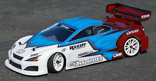
I had the Protoform body custom painted, but don’t be afraid to try painting it yourself.

Step 140
I chose to go with a set of Solaris pre-mounted wheels and tires. This setup works great at my local outdoor track. Slide them on and secure them with the M4 locknut.

Step 141
If you waited until this point to paint your body, you’ve made a smart choice. Marking the body mount locations and tire cutouts on a clear body is SO much easier than a painted one. Either way, drop your body on and slide the body pins in place.
There you have it; a complete A-Z TC6.1 build. I hope this has helped you in this process. Thanks for following along with this build and let your friends know it’s here.
Source:

|
